Transcription
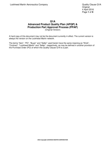
Product Design (Part 4)
Engineering DrawingChapter 16
Drawing Standards Line conventions and letteringANSI/ASME Y14.2M-1992 Multiview and sectional view drawingsANSI/ASME Y14.3M-1994 Pictorial drawing-ANSI/ASME Y14.4M1989(1994) Dimensioning and tolerancingANSI/ASME Y14.5M-1994
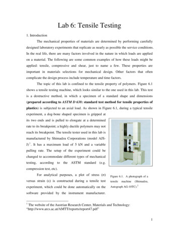
Line Types
Line TypesF 16-1
Engineering Drawing
Multiview ProjectionF 16-2 Standards
Projection SymbolsF 16-3 Symbols
Third Angle ProjectionF 16-4 Six principal views
Primary Auxiliary ViewF 16-5 Auxiliary view
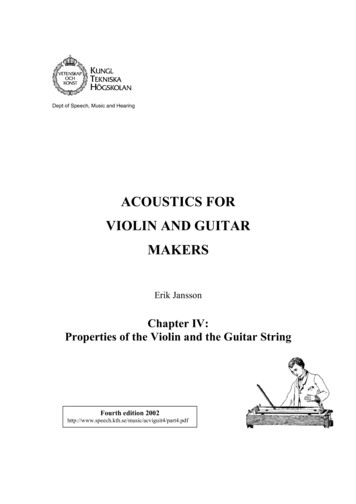
Full Section
Half SectionThis side drawn in sectionImagine this place ofthe part removed.This side drawn as exterior view
Offset Section
Offset SectionCutting planeDo now show bendsin the cutting plane
DimensioningF 16-8 Basic dimension
DimensioningF 16-9 Reference dimension
DimensioningF 16-10 Types of dimensioning
TolerancingF 16-11 Mating parts (inches)
TolerancingF 16-12 Mating parts (inches)
TolerancingF 16-13 Tolerances (inches)
System of Fits Hole basis: The system of fits where theminimum hole size is the basic size. Shaft basis: The system of fits where theminimum shaft size is the basic size
Fit Types Clearance: Gap between mating parts Interference: No clearance, force requiredfor assembly Transition: Result in either a clearance or aninterference fit
Types of Fits RC-running and sliding fitsLC-clearance locational fitsLT-transition locational fitsLN-interference locational fitsFN-force and shrink fits
Hole BasisShaft BasisDescriptionH11/c11C11/hllLoose running fit for wide commercial tolerances orallowances on external members.H9/d9D9/h9Free running fit for running accurate machines andfor accurate location at moderate speeds and journalpressures.H8/f7F8/h7Close running fit for running on accurate machinesand for accurate location at moderate speeds andjournal pressures.H7/g6G7/h6Sliding fit not intended to run freely, but to move andturn freely and locate accurately.H7/h6H7/h6Locational clearance fit provides snug fit for locatingstationary parts: but can freely assembled anddisassembled.
Hole BasisShaft BasisDescriptionH7/n6N7/h6Location transition fit for more accurate locationwhere greater interference is permissible.H7/p6P7/h6Locational interference fit for parts requiring rigidityand alignment with prime accuracy of location butwithout special bore pressure requirements.H7/s6P7/h6Medium drive fit for ordinary steel parts or shrink fitson light sections, the tightest fit usable with cast iron.H7/u6U7/h6Force fit suitable for parts which can be highlystressed or for shrink fits where the heavy pressingforces required are impractical.
Symbols and Their Definitions as Applied Holes and Shafts Basic Size HOLE Tolerance Grade40 H8 Fundamental Deviation IT Grade Basic Size Tolerance Grade SHAFT40 F7 Fundamental Deviation IT Grade Basic Size FIT Hole Tolerance Fit40 H8/f7 Shaft Tolerance
Tolerances for InterchangeabilityF 16-14 Car knob assembly
Surface TextureF 16-15 Criteria
Surface SymbolsF 16-16 Standard lay Designations
Surface SymbolsF 16-17 Applications
Geometric Dimensioningand TolerancingChapter 17
F 17-1 ASME Y14.5M-1994
F 17-2 GD&T Tolerances and Symbols
F 17-3 Feature control frame
F 17-4 Flatness
F 17-5 Surface Straightness
F 17-6 Axis straightness
F 17-7 Axis straightness
F 17-8 Circularity
F 17-9 Cylindricity
F 17-10 Parallelism
F 17-11 Perpendicularity
F 17-12 Angularity
F 17-13 Circular runout
F 17-14 Total runout
F 17-15 Profile of a line
F 17-16 Profile of a surface
F 17-17 Concentricity
F 17-18 Symmetry
F 17-19 Tolerance of position
Computer-Aided DesignChapter 18
3D Modeling Methods 1. Wire Frame 2. Surface Modeling 3. Solid Modeling
Wire FrameA. Advantages1. Easiest to construct2. Infinite number of views possibleB. Disadvantages1. Difficult to visualize complex objects2. Mass properties cannot be calculated
Surface ModelingA. Advantages1. Better representation of object compared towire frame2. Can be used to determine machine tool pathsB. Disadvantages1. Not a complete representation of real object2. Cannot be sectioned
Solid ModelingA. Advantages1. True 3D object2. Elimination of ambiguity in viewing model3. Section cuts can be produced and displayed4. Mass properties may be calculatedB. Disadvantages1. Software more expensive2. More memory is required
Modeling Uses
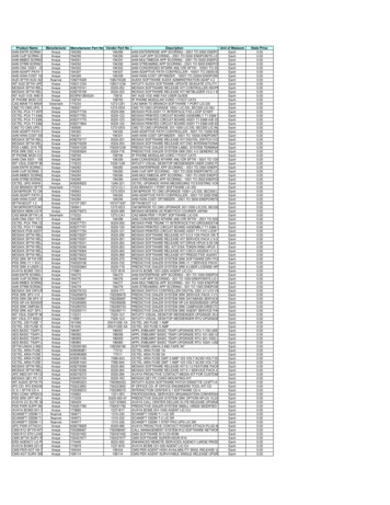
Circuit Board Layout CAD software designed for printed circuitboards (PCB) has features unique to thatapplication.Current surface mount technology (SMT)and the continued miniaturization ofintegrated-circuit products makes thedesign of most PCBs a complex task
PCB Design Considerations The number of layers in a final boardassembly (single-sided, double sided, andmultilayered)The miniaturization of components andthe effect on pin spacing and number ofpins in a conductorConductor routing and board layers
Design Considerations Contd. The frequency of the current in thedifferent circuits and the resultinginductanceHeat dissipationThe placement of similar types ofcomponents
Rapid Prototyping Methods Stereolithography apparatus (SLA)Solid ground curing (SGC)Laminated object manufacturing (LOM)Fused deposition modeling (FDM)Selective laser sintering (SLS)Ballistic particle manufacturing (BPM)
Advantages of RapidPrototyping Produce three dimensional parts within hoursCreate masters and patternsAccelerate prototype productionAchieve major savings in production of soft andhard toolingIncrease manufacturing capabilities with lowvolume production runsAdd impact to marketing concept presentationswith hands-on modelsImprove the accuracy of vendor bid response
Disadvantages of RapidPrototyping Parts typically cannot be used for physicaltestingParts have surface finish quality andtolerance limitationsSpecial techniques and materials arerequired of some systemsEquipment is expensive
Product Design ToolsChapter 19
Manufacturing Strategies Customer Response Entrepreneurial Manufacturing Time Based Strategy Managing For Speed Product
Customer Responsive Targets quality improvement and customerservice Uses short-run manufacturing via the workcell concept
Entrepreneurial Manufacturing Requires flexible system capable ofshifting from one product to another onshort notice Success is dependent upon a company’scapacity to create new markets forspecialized high-value-added products.
Time Based Strategy Organization of process components andstandardization Length of production run Complexity of scheduling procedures Favors smaller increments of improvement innew products, but introduces them more often
Managing for Speed ProductDepends on: Organizing product development for speed Organizing product manufacturing for speed Using miscellaneous techniques for speed Using computer-aided technology for speed
Manufacturing turingAll strategies focus on delivering a quality product at acompetitive price simultaneously responding to customerneeds, and striving for continuous improvement.Time BasedStrategyManaging ForSpeed Product
Concurrent Engineering Principles T 19-1Understand your customerUse product development teamsIntegrate process designInvolve suppliers and subcontractors earlyUse digital product modelsIntegrate CAE, CAD, and CAM toolsUse quality engineering and reliabilitytechniquesCreate an efficient development approachImprove the design process continuously
F 19-1 Process failure mode and analysis
Quality Function Deployment(QFD) A strategy/technique of listening to the“voice of the customer”
Benefits of Using a Quality FunctionDeployment Strategy T 19-6Earlier determination of key product characteristicsDocumentation of actual customers’ needs rather thandecisions based on opinionsReduction in product development costsReduction in time required to bring a new product tomarketGreater customer satisfaction due to lower costs andimproved responsivenessReduction in number of engineering changes across theproduct’s life cycle
Quality Function Deployment (QFD)F 19-2 Four stages of QFD
F 19-3 House of quality
F 19-4 QFD matrices
Group Technology (GT) An approach to reduce manufacturingsystem information content by identifyingand exploiting the sameness or similarity ofparts based on their geometrical shapeand/or similarities in their productionprocess.
Part Families Design-oriented: Have similar designfeature, such as geometric shape Manufacturing-oriented: Can be based onany number of different considerations,such as parts manufactured by the sameplant or same materials
Methods of Grouping Parts Visual inspection Production flow analysis (PFA) Classification and coding(Most effective and widely used)
Two Main Coding Systems1. Attribute-based (polycodes)2. Hierarchical-based (monocodes)
F 19-5 Attribute-based coding
F 19-6 Hierarchical-based coding
ANSI/ASME Y14.5M-1994 . Line Types . Line Types F 16-1 . Engineering Drawing . Multiview Projection F 16-2 Standards . Projection Symbols F 16-3 Symbols . Third Angle Projection F 16-4 Six principal views . Primary Auxiliary View F 16-5 Auxiliary view . Full Section . Half Section This side drawn as exterior view Imagine this place of the part removed. This side drawn in section . Offset .