Transcription
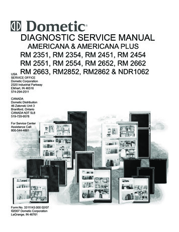
DIAGNOSTIC SERVICE MANUALAMERICANA & AMERICANA PLUSRM 2351, RM 2354, RM 2451, RM 2454RM 2551, RM 2554, RM 2652, RM 2662RM 2663, RM2852, RM2862 & NDR1062USASERVICE OFFICEDometic Corporation2320 Industrial ParkwayElkhart, IN 46516574-294-2511CANADADometic Distribution46 Zatonski Unit 3Brantford, OntarioCANADA N3T 5L8519-720-9578For Service CenterAssistance Call:800-544-4881Form No. 3311143.000 02/07 2007 Dometic CorporationLaGrange, IN 46761
Safety InstructionsForewordThis service manual is the result of the dedication of The Dometic Corporation Technical staffand its engineers in giving service people thenecessary instruction for making accurate analyses of certain conditions. Provided is a diagnostic chart leading a qualified mechanic into theservice manual pages to locate and solve symptoms which may occur. Dometic has continuedits commitment in providing service people withthis, the most up-to-date information about servicing Dometic RV accessories.This manual has safety information and instructions to help users eliminate or reduce the riskof accidents and injuries.Recognize Safety InformationThis is the safety-alert symbol. When you see thissymbol in this manual, be alert to the potentialfor personal injury.Follow recommended precautions and safe operating instructions.Understand Signal WordsA signal word , WARNING OR CAUTION is usedwith the safety-alert symbol. They give the levelof risk for potential injury.Indicates a potentially hazardous situation which, if not avoided, could resultin death or serious injury.Indicates a potentially hazardous situation which, if not avoided may result inminor or moderate injury.When used without the safetyalert symbol indicates, a potentially hazardoussituation which, if not avoided may result in property damage.Read and follow all safety information and instructions.
CONTENTSPAGE NO.DIAGNOSTIC FLOW CHART. 4SECTION 1OPERATIONRefrigerator Operation .6SECTION 2AC VOLTAGEAC Voltage Requirements.9SECTION 3AC COMPONENTSHeating Element .10SECTION 4DC VOLTAGEDC Voltage Requirements .10SECTION 5DC .135.14DC heating Element .11Thermistor .11Solenoid Valve.11Igniter .11High Voltage Cable .12Electrode.12DC Relay.12Upper Circuit Board .13Lower Circuit Board .13Door Switch .18Climate Control Heater & Switch .18Low Ambient Switch .18Fuses.18Thermofuse.18SECTION 6LP GASLP Gas Requirements .19SECTION 7LP GAS COMPONENTS7.17.27.37.4Manual Gas Shut-Off Valve .19Orifice .19Thermocouple .20Burner .20
CONTENTSPAGE NO.SECTION 77.5 Flue Baffle.207.6 Flue Cap .207.7 Flue Tube .20SECTION 8COOLING ion.21Air Leaks.23Interior Liner Seal to Frame.23Door Position.24Ambient Temperature.24Cooling Unit.25Food Storage.26High Humidity.26SECTION 9WIRING9.1 Internal Wiring.269.2 External Wiring.269.3 Wiring Schematics.26SECTION 10ICE MAKER10.1 Operation.2610.2 Mold Heater.2710.3 Ice Ejector.2710.4 Mold Thermostat.2710.5 Shut Off Arm.2710.6 Mold Switches.2710.7 Timing Motor.2810.8 Water Valve.2810.9 Ice Maker Replacement.2810.10 Water Fill Adjustment.2810.11 Water Supply.2910.12 Wiring Schematics.29
This program will address the most common system problems associated with the RM2351, RM2354, RM2451, RM2454,RM2551, RM2554, RM2652 ,RM2662,RM2663,RM2852and RM2862 refrigerators supplied by The Dometic Corporation.Our intent is to provide you with a guideline of checks to make, should you encounter one of the following symptoms.SYMPTOMCAUSESECTION & PAGE1.No operation - no panel lightsOperationDC VoltsFuseWiringUpper Circuit BoardLower Circuit Board1, page 064, page 105, page 189, page 265, page 135, page 132.No operation - has panel lightsOperationDC VoltsThermistorWiringLower Circuit Board1, page 064, page 105, page 119, page 265, page 143.No AC operation - operates on gas modeOperationAC VoltsFuseHeating ElementWiringLower Circuit Board1, page 072, page 095, page 193, page 119, page 245, page 134.No Gas operation - operates on AC modeOperationLP GasManual Gas ValveIgniterHigh Voltage CableElectrodeSolenoidWiringLower Circuit Board1, page 066, page 197, page 195, page 115, page 125, page 125, page 119, page 245, page 135.Insufficient cooling on all modes.VentilationLevelingAmbient TemperatureAir LeaksThermistorCooling Unit8, page 218, page 218, page 248, page 235, page 118, page 256.Insufficient cooling on AC - cools properlyon gas mode.AC VoltsHeating ElementLower Circuit Board2, page 093, page 105, page 137.Insufficient cooling on Gas - cools properlyon AC mode.LP GasOrificeFlue BaffleFlue TubeBurnerLower Circuit Board6, page 197, page 197, page 207, page 207, page 205, page 138.Freezes.OperationThermistorLower Circuit Board1, page 065, page 125, page 14
SYMPTOMCAUSESECTION & PAGE9.DC VoltsWiringLP GasManual Gas ValveSolenoidOrificeBurnerThermocoupleLower Circuit Board4, page 109, page 266, page 197, page 195. page 117. page 197. page 207. page 205. page 1310. Interior light on when door is closedWiringLow Ambient SwitchDoor SwitchDoor Position9. page 265. page 185. page 188. page 2411. Rapid formation of frostFood StorageInterior Liner to FrameHigh HumidityAir Leaks8. page 268. page 238. page 268. page 2312.Interior Liner to FrameHigh HumidityAir LeaksClimate Control Heater8. page 238. page 268. page 235. page 18Check light onWater on frame
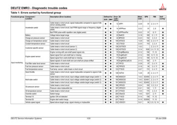
SECTION 1REFRIGERATOR OPERATIONDISPLAY PANEL RM2351, RM2451, RM2551, RM2652, RM2852AUTO TEMPERATURE CONTROLRefrigerator Control PanelRM2652 & RM2852RM2662 & RM2862AMERICANA 2-WAY MODEL1. Main Power Button ON/OFF2. AUTO/GAS Mode Selector ButtonRM2451 & RM2551A. AUTO Mode indicator lampB. CHECK indicator lamp (Gas ModeOnly)C. Climate control switch only onRM2652 & RM2862Travel Latch RM2351
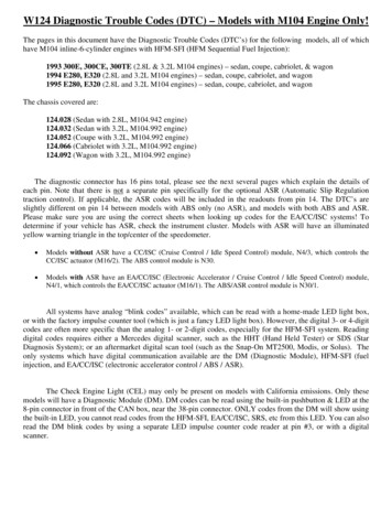
DISPLAY PANEL RM2354, RM2454, RM2554 RM2663 3-wayDISPLAY PANEL RM2662, RM2862 2-WAYRefrigerator Control Panels3-WAY2-WAY3-WAYRM2454 & RM2554Travel Latch RM23541. Main Power Button ON/OFF2. DC Mode Selector Button3. AUTO/GAS Mode Selector Button4. Temperature Selector ButtonA. DC Mode Indicator LampB. AC Mode Indicator LampC. GAS Mode Indicator LampD. AUTO Mode Indicator LampE. CHECK Indicator Lamp(Gas Operation Only)F. Temperature Indicator Lamps2-WAY1. Main Power Button ON/OFF2. AUTO/GAS Mode Selector Button3. Temperature Selector ButtonB. AC Mode Indicator LampC. GAS Mode Indicator LampD. AUTO Mode Indicator LampE. CHECK Indicator Lamp( GAS Mode Only)F. Temperature Indicator Lamps
OPERATION INSTRUCTIONSOPERATIONAuto ThermostatA. A continuous 12 volt DC supply must be available forthe electronic control to function.B. Press the main power ON/OFF button (1) tothe DOWN position.C. In AUTO mode, the AUTO lamp A will be illuminated.The control system will automatically select betweenAC and GAS operation with AC having priority. Thetemperature is controlled by a factory preset temperature setting.D. In GAS mode operation, no lamps will be illuminatedand the temperature is controlled by a factory presettemperature setting.IMPORTANCE OF LEVELING AREFRIGERATORIn an absorption refrigerator system, ammonia is liquefiedin the finned condenser coil at the top rear of the refrigerator. The liquid ammonia then flows into the evaporator(inside the freezer section) and is exposed to a circulating flow of hydrogen gas, which causes the ammonia toevaporate, creating a cold condition in the freezer. Whenstarting this refrigerator for the very first time, the coolingcycle may require up to four hours of running time before the cooling unit is fully operational. The tubing in theevaporator section is specifically sloped to provide a continuous movement of liquid ammonia, flowing downwardby gravity through this section. If the refrigerator is operated when it is not level and the vehicle is not moving, liquid ammonia will accumulate in sections of the evaporatortubing. This will slow the circulation of hydrogen and ammonia gas, or in severe cases, completely block it, resulting in a loss of cooling. Any time the vehicle is parked forseveral hours with the refrigerator operating, the vehicleshould be leveled to prevent this loss of cooling. The vehicle needs to be leveled only so it is comfortable to live in(no noticeable sloping of floor or walls). When the vehicleis moving, the leveling is not critical, as the rolling andpitching movement of the vehicle will pass to either sideof level, keeping the liquid ammonia from accumulating inthe evaporator tubing.OPERATIONAdjustable ThermostatA. A continuous 12 volt DC supply must be available forthe electronic control to function.B. Press the main power ON/OFF button (1) to the DOWNposition.C. In AUTO mode, the AUTO lamp D will be illuminated.The control system will automatically select betweenAC and GAS operation with AC having priority. Temperature is selected by the user.D. In GAS mode operation, the GAS lamp C will be illuminated and only operate on LP only. Temperature isselected by user.E. In DC mode, the DC lamp A will be illuminated and theunit will only operate on DC until DC volts drops below9.6 VDC.OPERATIONBefore starting the refrigerator, check that all the manualgas valves are in the ON position. DO NOT forget themanual shutoff valve on the rear of the refrigerator. Thisrefrigerator is equipped with a control system which canbe set to automatically select either 120 volt AC or LP gasoperation (AUTO mode), or if desired LP gas only (GASmode) or DC volts (DC Heater) where applicable.Auto ThermostatIn both AUTO mode and GAS mode operation, the temperature is controlled by a factory preset temperature setting. The refrigerator controls will work down to 9.6 voltDC.Auto ModePress the AUTO/GAS button 2 (Auto Thermostat) or button 3 (Adjustable Thermostat) to the DOWN position. TheAUTO mode indicator lamp (A auto or D adjustable thermostat) will illuminate. If 120 volts AC is available, thecontrol system will select AC operation. If 120 volts AC isnot available, the control system will automatically switchto GAS operation. Within 45 seconds the burner shouldbe ignited and operating normally. If the CHECK indicatorlamp (B auto or E adjustable thermostat) illuminates, thecontrol has failed to ignite the burner on GAS. To resetwhen the CHECK indicator lamp, press the main powerON/OFF button (1) to the OFF then ON position. Systems with the new lower control board are a three (3) trysystem on gas. On the initial refrigerator start-up on gas(120 volts AC is not available), it may take longer than 45seconds to allow air to be purged from the gas line. If therefrigerator has not been used for a long time or the LPtanks have just been refilled, air may be trapped in thesupply lines. To purge the air from the lines may requireresetting the main power ON/OFF button (1) three or fourtimes. If repeated attempts fail to start the LP gas operation, check to make sure that the LP gas supply tanks arenot empty and all manual shutoff valves in the lines areopen.Most LP gas appliances used in recreational vehicles are vented to the outside of thevehicle. When parked close to a gasolinepump, it is possible that the gasoline fumescould enter this type of appliance and ignitefrom the burner flame, CAUSING A FIRE ORAN EXPLOSION.FOR YOUR SAFETY, when refueling, shutoff all LP gas appliances which are ventedto the outside.
a period of approximately 45 seconds with two minutes (purge) interval after each trial. If unsuccessful, theCHECK indicator lamp (B) will illuminate. To restart GASoperation, press the main power ON/OFF button (1) tothe OFF and then ON position. The control system willattempt a new ignition sequence. If the refrigerator hasnot been used for a long time or the LP tanks have justbeen refilled, air may be trapped in the supply lines. Topurge the air from the lines may require resetting the mainpower ON/OFF button (1) three or four times. If repeatedattempts fail to start the LP gas operation, check to makesure that the LP gas supply tanks are not empty and allmanual shutoff valves in the lines are turned on.Note: Do not continue to reset GAS operation if theCHECK indicator lamp continues to be illuminated afterseveral tries.GAS ModeMove the AUTO/GAS button 2 (Auto Thermostat) or button3 (Adjustable Thermostat) to the UP position. The AUTOmode indicator lamp (A) will go off. Within 45 seconds theburner should be ignited and operating normally.DC Mode 3 Way Units OnlyPress the DC mode indicator button (2) to the DOWNposition. (Lamp [A] will light). Press the TEMPERATURESELECTOR button (4) until the lamp (F) at the desiredposition is illuminated. The refrigerator will continue to operate in the DC mode until switch (2) is moved to the UPposition or control voltage falls below 9.6 VDC. The DCmode overrides all the other operating modes. Discharging of the battery will occur if the vehicle engine is notrunning.Note: The DC mode is a holding mode not a full cooling mode. DC should be used once the unit is cooleddown and constant supply of DC available (drivingdown the road).DC Mode 3 Way Units OnlyPress the DC mode indicator button (2) to the DOWNposition. (Lamp [A] will light). Press the TEMPERATURESELECTOR button (4) until the lamp (F) at the desiredposition is illuminated. The refrigerator will continue to operate in the DC mode until switch (2) is moved to the UPposition or control voltage falls below 9.6 VDC.The DC mode overrides all the other operating modes.Discharging of the battery will occur if the vehicle engineis not running.Note: The DC mode is a holding mode not a full cooling mode. DC should be used once the unit is cooleddown and constant supply of DC available (drivingdown the road).To Shut Off The RefrigeratorThe refrigerator may be shut off while in any mode ofoperation by pressing the main power ON/OFF button tothe UP (OFF) position. This shuts off all DC power to thecontrol system.Description Of Operating ModesAuto ModeTo Shut Off The RefrigeratorWhen operating in the AUTO mode, the AUTO mode indicator lamp (A) will illuminate. The control system willautomatically select between AC and GAS operation withAC having priority over GAS. If the control system is operating with AC energy and it then becomes unavailable,the system will automatically switch to GAS. As soon asAC becomes available again the control will switch backto AC operation. Gas operation (120 volts AC is not available). The control system will activate the ignition system and will make three attempts to light the burner fora period of approximately 45 seconds with two minutesrest (purge) interval. If unsuccessful, the CHECK indicator lamp (B) will illuminate. To restart an ignition attemptwith the CHECK lamp illuminated or to clear (turn off) theCHECK lamp, press the main power ON/OFF button tothe OFF position and wait a few seconds, then return tothe ON position. The control system will attempt a new ignition sequence. If 120 volts AC becomes available whilethe CHECK indicator lamp is on, the CHECK lamp will notturn off until the main power ON/OFF button is pressedto the OFF then ON position but the unit will operate onAC.The refrigerator may be shut off while in any mode ofoperation by pressing the main power ON/OFF button tothe UP (OFF) position. This shuts off all DC power to thecontrol system.Limp ModeThis control system contains a feature where it will continue to operate the cooling system in event of a failure ofa major operating component. If the control cannot readthe temperature sensor and control to the preset temperature, then the control will run the cooling unit continuously at the energy source available. The refrigerator willcontinue to operate in this mode indefinitely or until a newsensor is installed and the system is reset.SECTION 2 AC VOLTAGEAC VOLTAGE REQUIREMENTSThis is an energized circuit. Shock can occurif not tested properly. Testing is to be doneby a qualified service technician.Gas ModeWhen operating in the GAS mode, the AUTO mode indicator lamp (A) will be off. This mode provides LP gas operation only. The control system will activate the ignitionsystem and will make three attempts to light the burner fora period of approximately 45 seconds with two minutesThe proper operating range is 100 to 132 volts. If voltagedrops below 100 volts, cooling efficiency will decreasewith voltage decrease.
The refrigerator will not switch to another mode of operation until all AC power is lost. The refrigerator is equippedwith a three-prong (grounded) plug for protection againstshock hazards, and should be plugged directly into aproperly grounded three-prong receptacle.SECTION 4 DC VOLTAGEDC Voltage RequirementsClean Direct Current (DC) power is mandatory for hightech circuits to operate as designed. A battery will providestraight line DC power. The converter and alternator produce DC power by a series of diodes that rectify alternating current to DC. The Dometic control system will onlytolerate up to 6 AC volts on the DC line. AC ripple can bemeasured by a digital voltmeter set on the AC scale at themain DC terminal block connections at the refer. Six voltsAC or less is acceptable. If AC volts exceed 6 on the DCincoming line the power source should be cleaned up. ACvoltage in excess of 6 volts will affect the processor andcreate erratic operation. When testing for AC ripple on theDC line put a load on the converter. The operational rangeof the unit is a minimum of 9.6V DC to a maximum of22V DC. The unit will automatically shut down until voltage has decreased to 18V DC. The refrigerator requiresat least 9.6V DC for proper operation; however the panellights will continue to illuminate until voltage has droppedto 4V DC or below. Do not use the body or chassis ofthe RV as a substitute for either of the two conductors.The refrigerator must be connected to the battery circuitwith two wires of adequate capacity to avoid voltage drop.Proper polarity is crucial for refrigerator operation.No other electrical equipment or lighting should beconnected to the refrigerator circuit. Just because youcan read volts does not mean you have the amps to operate the control system. If relays buzz, lights go dim or outduring operation, this could indicate there is a loose connection somewhere.SECTION 3 AC COMPONENTSHeating ElementThe heating element is designed to deliver a predetermined amount of heat to the cooling unit. To check a heating element, remove the heater leads from the printedcircuit board and measure for proper resistance acrossthe two leads with a properly calibrated ohm meter. Thischeck is to be done with the heating element at roomtemperature. You should obtain the following readings 10%:Main Terminal BlockModelWATTSOHMSAMPSRM2351-4 175801.5RM2451-4 175801.5RM2551-4 175801.5RM2652325442.7RM2662-3 325442.7RM2852325442.7RM2862325442.7Never over or under size the AC heater.GroundsThe operation of the Dometic refrigerator is also dependent on good, clean ground connections. Loose or corroded ground terminals create an unknown resistance factorthat can affect the voltage detected by the Power Module.A loose negative DC wire will create a negative millivoltsignal that the control board will pick up and create erraticoperation. Check the integrity of the grounds from the refrigerator all the way to the power source/battery. Clean ortighten any suspicious looking connections.Note: The DC terminal block below the control boardshould be cleaned and tightened at the 4 wires.10
SECTION 5 DC COMPONENTS5.1 DC Heating ElementRemove the heater leads from the lower circuit board orrelay and measure for proper resistance across the twoleads. You should obtain the following readings OTE: The DC mode is a holding mode not a full coolingmode. DC should be used once the unit is cooled down ongas or AC and driving (constant supply of DC) down theroad. A continuity reading will indicate an open or complete circuit. Never over or under size the DC heater.5.3 Solenoid ValveCheck the solenoid coil with a properly calibrated ohmmeter. Remove the connectors from the solenoid andmeasure the resistance across the terminals. The properreading would be 49 ohms with tolerance range of tenpercent. Failure of the solenoid is very unlikely. Next,hook up a manometer at the test port. Then check for DCvolts at gas valve terminals (Yellow White -) while theunit is in trial-for-ignition. If DC volts are present and pressure is low, replace the valve. If DC volts are not presentat the valve while the unit is in trial-for-ignition, verify thatthe wire at Plug 3, Terminal 2 on lower circuit board hasDC volts (9 or more).5.2 ThermistorDisconnect the thermistor harness from the P2, 2-pin terminal on the lower circuit board. Place the thermistor ina glass of ice water (more ice than water), approximately33 F to 35 F. Wait 8 to 10 minutes. You should get areading of approximately 8,000 to 10,000 ohms. Alwaystest from the wire side as shown with the meter as not tocreate a connection problem at the P2 connector.5.4 Igniter11The igniter used on Dometic model refrigerators operateson 12 volt DC. On gas operation the igniter senses theresistance through the flame between the electrode andburner. When there is no flame at the burner, the resistance is high and the igniter begins sparking to light theburner. As soon as the flame is lit, the resistance betweenthe electrode and burner drops and the igniter stopssparking. The resistance is monitored by the igniter, and,if for any reason the flame goes out, the igniter beginssparking until the burner is lit. The resistance between theelectrode and burner drops and the igniter stops sparking.
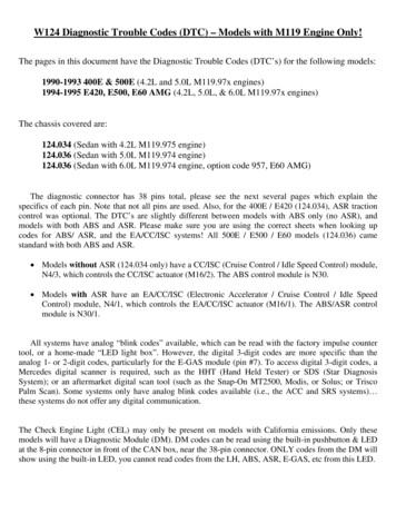
5.5 High Voltage CableIf sparking starts during trial-for-ignition, the cable is good.If there is no sparking during trial-for-ignition, disconnectDC power at the refrigerator terminal block or switch unitoff. Disconnect high voltage cable from electrode. Reconnect DC power. If there is a sparking sound from theigniter during trial-for-ignition, then replace high voltagecable or electrode. On newer units the electrode and highvoltage cable are integrated into one component.This is an energized circuit. Shock can occurif not tested properly. Testing is to be doneby a qualified service technician.This insures that the flame will always be lit when desired. First verify proper voltage at the positive (Yellow ) and ground (Black –) terminals of the igniter. The reading should be within 1.5 volt of incoming voltage at themain terminal block during trial-for-ignition. Next, removethe high voltage cable from the igniter. The igniter shouldproduce a sparking sound during trial-for-ignition. If not,replace the igniter. While operation is in the gas mode, thepower module and igniter are constantly monitoring thepresence of flame. If the flame is blown out, the reignitorwill immediately start sparking. When the power modulesenses the loss of flame (thermocouple voltage below 13MVDC) the 45 seconds trial for ignition period is started. The igniter installed on the refrigerators as originalequipment is part number 2931132019 (RV Gas Model679). This igniter is rated 50 MA. This igniter may also beused on any other model. When replacing the igniter always provide the product number for proper replacement.DO NOT install the Channel Mark 6, Model 12 E igniter(shown below) as a service replacement part. Installationof the Channel Products, Inc., Gasliter Mark 6, Model 12E, will VOID the Warranty on the refrigerator. To acquirethe proper igniter always provide the product number.5.6 ElectrodeDo a visual check for cracks or breaks on the ceramic insulator. A hair line crack can be hard to see at the electrode.The spark gap must be set at three-sixteenths (3/16”) ofan inch and tip of electrode above the slots in the burner.When adjusting always loosen the screw and move intoplace, never try to move without loosing the screw. Onnewer units the electrode and high voltage cable are integrated into one component. To acquire the proper partalways provide the product number.5.7 DC RelayThe relay controls the circuit to the DC heating element. The load (amps) of the DC heating element goesthrough the relay. Only used on newer 3 way units orunits that have the UNIVERSAL POWER MODULE KIT(3308742.000) installed.P3 HarnessBlue Wire85( ) 12 VDCHeater Element Wire8730Red BatteryWire86P3 HarnessBlue WireVerify that the following components are good: upper circuit board, thermistor, 5 or 6 wire harness and 30/3-ampfuses. In the DC mode Plug 3, Terminal 4 (positive 86)and Terminal 3 (negative 85) should have voltage to closethe relay. If no voltage in the DC mode change the lowerboard.12
Wires from control board P3 harness to relay.Terminal 85 P3-3 harness blue negative.Terminal 86 P3-4 harness blue positive.Wires to relay from DC source and DC heater.Terminal 87 to DC heater positive.Terminal 30 positive from DC power source.If DC voltage to terminals 85 & 86, but no continuity between 30 & 87 the relay will need to be changed. Refer towiring diagram on the back of the product or check partslist for proper diagram. To acquire the proper wiring diagram always use the product number.5.9 Lower Circuit BoardWIRING Original style control 3 way & 2 wayNote: 2 Way will not have a J1 for DC heaterP1 To upper control boardP2 ThermistorP3 To gas valve, igniterJ1 To DC heaterJ2 To interior light and climate controlJ3 Negative lead from thermocoupleJ4 Positive 12V DC from terminal blockJ5 AC line voltage (Black)J6 AC neutral line (White)J7 AC neutral out to AC heaterJ8 AC line out to AC heater Switched sideJ10 Positive lead from thermocoupleThermocouple positive lead may be on the ground stripon early units. Reference full wiring diagram next page.5.8 Upper Circuit BoardWith main ON/OFF switch on display panel in OFFposition: C
10.10 Water Fill Adjustment.28 10.11 Water Supply.29 10.12 Wiring Schematics.29. 4 SYMPTOM 1. No operation - no panel lights 2. No operation - has panel lights 3. No AC operation - operates on gas mode 4. No Gas operation - operates on AC mode 5. Insufficient cooling on all modes. 6. Insufficient cooling on AC - cools properly .