Transcription
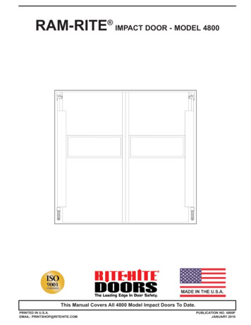
RAM-RITE IMPACT DOOR - MODEL 4800This Manual Covers All 4800 Model Impact Doors To Date.PRINTED IN U.S.A.EMAIL: PRINTSHOP@RITEHITE.COMPUBLICATION NO. 4800FJANUARY 2010
RAM-RITE Model 4800PRODUCT INTRODUCTIONINSTALLATION INSTRUCTIONS . . . . . . . . . . . . . . . . . . . . .3MOUNTING BRACKET INSTALLATION . . . . . . . . . . . . . . . .4HINGE/CAM INSTALLATION . . . . . . . . . . . . . . . . . . . . . . . . .5BUMPER INSTALLATION . . . . . . . . . . . . . . . . . . . . . . . . . . .6DOOR PANEL INSTALLATION . . . . . . . . . . . . . . . . . . . . . . .7HARDWARE SHIMMING AND CAM ALIGNMENT . . . . . . . .8SEAL INSTALLATION . . . . . . . . . . . . . . . . . . . . . . . . . . . . . .9SPRING ADJUSTMENT . . . . . . . . . . . . . . . . . . . . . . . . . . . . .9FLOOR, LINTEL AND CHAIN LOCK INSTALLATION . . . . .10HOLD OPEN PIN INSTALLATION . . . . . . . . . . . . . . . . . . . .11FINAL INSTALLATION CHECK . . . . . . . . . . . . . . . . . . . . . .11LUBRICATION . . . . . . . . . . . . . . . . . . . . . . . . . . . . . . . . . . .11TROUBLESHOOTING . . . . . . . . . . . . . . . . . . . . . . . . . . . . .12ARCHITECTURAL DRAWING . . . . . . . . . . . . . . . . . . . . . . .12NOTICE TO USEROur mission is to “Improve Industrial Safety, Security andProductivity Worldwide through Quality and Innovation.”Thank you for purchasing the RAM-RITE model 4800 impactdoor from RITE- HITE DOORS, INC. The RAM-RITE is aswinging impact door designed for areas with heavy traffic. Thedoor has excellent sealing, appearance and durability. Thisowners manual MUST be stored near the door. RITE-HITEDOORS, INC. reserves the right to modify any drawings in thismanual as well as the actual parts used on this product aresubject to manufacturing changes and may be different thanshown in this manual. Due to unique circumstances withvarying requirements, separate prints may be included with theunit.This manual should be thoroughly read and understood beforebeginning the installation, operation or servicing of this door.Refer to partslist manual for exploded views and part numbers.The information contained in this manual will allow you tooperate and maintain the door in a manner which will insuremaximum life and trouble free operation. The serial # for yourdoor is on a label located on the vision and/or the stile.Your local RITE-HITE DOORS, INC. Representative providesthe Planned Maintenance Program (P.M.P.) which can be fittedto your specific operation. If any procedures for the installation,operation or maintenance of the RAM-RITE impact door havebeen left out of this manual or are not complete, contact RITEHITE DOORS, INC. Technical Support at 1-563-589-2722.RITE-HITE DOORS, INC. are covered by one or more of thefollowing U.S. patents, including patents applied for, pending, orissued: 5,025,846, 5,143,137, 5,203,175, 5,329,781, 5,353,859,5,392,836, 5,450,890, 5,542,463, 5,579,820, 5,601,134,5,638,883, 5,655,591, 5,730,197, 5,743,317, 5,794,678,5,887,385, 5,915,448, 5,944,086, 5,957,187, 6,042,158,6,089,305, 6,098,695, 6,145,571, 6,148,897, 6,192,960,6,321,822, 6,325,195, 6,330,763, 6,352,097, 6,360,487,6,574,832, 6,598,648, 6,612,357, 6,615,898, 6,659,158FEATURES- Heavy-duty construction, which will withstand repeated use ofmotorized vehicles.- Full-length stile and shaft, ductile iron cam rise hardware.- 24” high, full-width vision - 4800- Full perimeter gasketing.- Maximum insulation filled with high density, lightweightpolystyrene foam, with 1/8” ABS facing.2RECOMMENDED TOOL LIST6’ Level, 16’ Tape Measure,. Punch, Utility Knife, Hammer, DrillBits (3/16”, 1/4”, 5/16”, Letter N)RECOMMENDED SPARE PARTS LISTCams, Followers, Bumpers, Springs and WashersCLEANING RECOMMENDATIONSDOOR FACINGClean facing with commercial, non-abrasive liquid cleaners ordetergents. Furniture polish can clean and sometimes restorefacing to original appearance.VISION PANELSIt is important to remove protective masking within 2 weeksafter exposure to sunlight or extreme temperatures. Cleanvision panel with mild soap or detergent and lukewarm water,using a soft clean sponge or soft cloth. DO NOT use abrasiveor alkaline cleaners, solvents, metal blades or scrappers.WARRANTYRITE-HITE DOORS, INC. warrants that its impact door model4800 will be free from defects in design, materials, andworkmanship for a period of two (2) years from the date ofshipment. The warranty covers material failure under normalwear conditions or failure and the labor to replace such parts. Itdoes not cover wear items, such as seals or labor fromdamage incurred from abuse, misuse or impact. All claims forbreach of this warranty must be made within thirty (30) daysafter the defect is or can, with reasonable care, be discoveredto be entitled to be benefits of this warranty, the products musthave been properly installed, maintained and operated withintheir rated capacities, and not otherwise abused. Periodicadjustment is the sole responsibility of the owner. This warrantyis RITE-HITE DOORS, INC.'S exclusive warranty. RITE-HITEDOORS, INC. expressly disclaims all implied warrantiesincluding the implied warranties of merchantability and fitness.Non-standard RITE-HITE DOORS, INC. warranties, if any,must be specified by RITE-HITE DOORS, INC. in writing.In the event of any defects covered by this warranty, RITEHITE DOORS, INC. will remedy such defects by repairing orreplacing any defective equipment or parts, bearing all of thecosts for parts, labor, and transportation, as long as the correctwarranty policies are followed. This shall be the exclusiveremedy for all claims whether based on contract negligence orstrict liability. Neither RITE-HITE DOORS, INC., or any othermanufacturer whose products are the subject of thistransaction, nor any RITE-HITE DOORS, INC. representative,shall in any event be liable for any loss or use of anyequipment or incidental or consequential damages of any kindwhether for breach of warranty, negligence or strict liability. Theapplication of a manufacturer's specifications to a particular jobis the responsibility of the purchaser.RITE-HITE DOORS Corporation8900 N. Arbon DriveP.O. Box 23043Milwaukee, Wisconsin 53223Sales: 414-355-2600Toll Free: 800-456-0600Aftermarket: 563-589-2781Service: 563-589-2722Service Fax: 563-289-2737Representatives in All Major Citieswww.ritehite.comPub. No. 4800F JANUARY 2010
RAM-RITE Model 4800INSTALLATION INSTRUCTIONS4.GENERAL INSTALLATION PROCEDURES1.The door that you will be installing is a swinging impactdoor. The following is basic information that you shouldreview before beginning the installation.X2.Type of option will have box checked3.Make sure you are working at the correct location.4.Barricade work area on both sides of the opening.5.Detour material handling equipment (forklifts trucks, etc.)during the installation of the door.6.Be sure that you have any special work or permits.Most jambs are NOT plumb and square, but Doors mustbe hung plumb and square. Door hardware (hinges) arepre-aligned at factory. Therefore, shims are provided tohang doors plumb and square.InstallationHere are a few things to verify before getting started:MAINTENANCE AND OPERATIONNOTE: It is recommended to set up a maintenanceschedule to suit your needs based upon yourusage of the doors.It is important to verify the door opening to the doorsize before starting with the installation.1.Measure the overall width of the door opening near thefloor and near the top (Dimension AA and BB),Figure 3.1. These measurement should be /- 1/4”.Compare these measurements to the size listed on theshipping carton for the door to be installed.2.Measure the height of the door opening at the left andright-hand sides (Dimensions CC and DD), Figure 3.1.These should be within /- 1/8” of the ordered door size.Serial number is located on vision panel and stile of door.If the measurements do not agree, STOP! Contact yourRITE- HITE DOORS, INC. representative.3.Verify that the door jambs are plumb, perpendicular andthat the header is level, dimensions are taken from thetop down. If the header is not level, level across from thelow side of jamb and reference all measurements fromlevel line, Figure 3.2.1.Check all hardware fasteners.2.Check alignment for vertical and horizontal squareness.Make sure doors open freely and close easily from openposition, to insure longer life of facing material.3.Inspect door facing for cuts and/or wear spots andmaterial separation. When excessive cuts, wear, orseparation of facing appear, contact your localRITE- HITE DOORS, INC. representative to replace part.Early detection and repair is the key to low costmaintenance.AALISTING OF MEASUREMENTS ANDMARKINGS REQUIREDLevelCC1.2.3.4.5.6.Door width at bottomDoor width at topDoor height leftDoor height rightMark left wall where water is level.Mark right wall where water is level.DBBHigh Side3.1Low SideHydro-Level3.2Check Opening forSquareness:If not Plumb orSquare, Shim Door, asDoor Must be PlumbLevel LineDoor OpeningHang DoorPlumbCheck for HighSpots in DoorwayPub. No. 4800F JANUARY 20103
RAM-RITE Model 4800MOUNTING BRACKET INSTALLATIONWELD PLATES270 WELD PLATE1.Mark the centerline of the jamb and plumb, Figure 4.1.1.2.Align guide marks of weld plates to vertical plumb lineand level. Position “shorter dimension” of weld plates up,toward header, Figure 4.1.Mark the centerline of the jamb. Plumb to bottom of jamb,measure 5” from header, Figure 4.2.2.Align guide marks of weld plates to vertical plumb lineand level. Position “shorter dimension” of weld plates up,toward header, Figure 4.2.3.Top or bottom weld plates are reversible as right or left,but 13/16” stud dimensions must always be mounted onwall (or 180 side).4.Weld the weld plates in position.Center the plate on the jamb. Lay a level on the studsand align the weld plate horizontally. Note the location ofthe 1 1/4” dimension toward top and measure 5 1/4”down to center of mounting studs from the door header.Be sure to follow location dimensions carefully.3.Tack-weld the plate in place temporarily.4.Repeat step two for the bottom weld plate. Make sure the3 3/8” stud spacing is toward the top. Measure from centerof studs at top weld plate, to center of top studs on bottomplate. Use dimension shown in box, Figure 4.1.1.Mark centerline at top of jamb, and plumb to bottom ofjamb, Figure 5.1 (180 ) or 5.2 (270 ).2.Align “L” brackets with center line.5.Again, tack-weld the plate in place temporarily.3.Mount “L” brackets to the jamb at the top and the bottom.6.Check all dimensions, and be sure plates are straightwith a plumb line, and horizontal. Proceed to weld platesin position, only if all dimensions and alignment arecorrect.7.“L” BRACKETSLintel4.25”Top Weld Plates 4 StudWeld along both outside edges of plates, using a 3/16”fillet weld. Grind off any weld that is higher than the topmounting surface of the plates.3/16”13/16”OFF-SET WELD PLATE1.See “Weld Plate Instructions” for proper weld platepositioning, Figure 4.1.2.This applies to all rising type doors. If dimensions are notlocated from the lowest point, the door will bump theheader and not fully open !4.1Bottom Weld Plate Detail(Showing Hinge and Jamb Guard in Place)Top Weld Plate.NOTE:1 1/4” DimensionToward Top of Jamb.5 1/4”1 1/4”13/16” refBottom WeldPlates2 & 6 Stud3/16” WeldTop andBottomTop Weld PlateReference AllMeasurementsFrom LowestPoint On HeaderTop Weld Plate (Blocked Out)(Bottom Weld Plate NotShown)Doors With Off-SetJamb Only905”3 3/8”Guide MarksPlumb line4 3/8”Bottom weld plate.NOTE: 3 3/8” dimensiontoward top of jamb1/2”10 1/4”Door BottomHinge3 3/8”1 1/4”Top3”Weld PlateJamb Guard4Pub. No. 4800F JANUARY 2010
RAM-RITE Model 4800MOUNTING BRACKET INSTALLATION4”5”Top “U”-Bracket NOTE: 1 1/4”Dimension Must be Toward Top5 1/4”90 5.33 3/8”1 1/4”8”DoorBottomHinge5 1/4”EqualMismatch ofCenter PlumbLines isUnacceptable.Center Line90 90 Center Line10 1/4”JambGuard3 3/8” Studsat Top“B”Bottom U-Bracket Mounting Detail(Showing Hinge and Jamb Guard in Place)“A”5.14”180 “L” BRACKETNOTE: Bearing plateA 2 3/4”Raised bearing plate3/16”FloorB 6”U-StrapBottom “U”-Bracket NOTE: 3 3/8” 3/8” Thd. Rod Thru orDimension Toward Top of Jamb Bracket and Wall BracketA 9 3/6” B 12”Header only(2 brackets)“U”-BRACKET DETAIL5.2Top “L” brackets5 1/4”Lintel5 1/4”90 3/16”CenterLine5.4DIM ‘A’13/16”3/16” WeldTop Only1 11/16”DIM ‘B’13/16” refBottom “L”bracketsFloor270 “L” BRACKET“U”-BRACKETSNOTE: For doors with jamb guards.1.2.3.4.Slide the plate around the jamb. Note the location of the1 1/4” dimension toward top and dimension 5 1/4” tomeasure down to center of mounting studs from the doorheader. Be sure to follow location dimensions carefully.Repeat step two for the bottom weld plate. Make sure the3 3/8” stud spacing is toward the top. Measure fromcenter of studs at top weld plate, to center of top studson bottom plate. Use the dimension shown in box at left.Check all dimensions, and be sure plates are straightwith a plumb line, and horizontal. Proceed to weld platesin position, only if all dimensions and alignment arecorrect.Drill thru plates and wall and thru-bolt using a minimum3/8” all-thread, Figure 5.3.Pub. No. 4800F JANUARY 20105.Drill/Tap for 3/8-16 bolts (4)places3 3/8”When jamb guards are used, position “shorter dimension”of the bottom weld plate toward floor. Refer to“HARDWARE SHIMMING” before welding.DRILL AND TAP JAMB MOUNTING1.Mark the centerline of the jamb. Plumb to bottom of jamb,Figure 5.4.2.Mark the mounting holes of DIM “A” & DIM “B” at 90 angles from center line.3.Center punch the hole locations and drill and tap for3/8-16 x 1 1/2” hex head machine screws.1 1/2” CAM INSTALLATIONNOTE: When installing doors, be sure high side of cam isto side opposite any air pressure on doors, Figure 6.1.270 HINGE MOUNTING1.NOTE: 1 7/16”’ and 13/16” dimensions are mounting holelocations on the jamb, Figure 6.2.2.Either left or right cam maybe used for single doors.3.Left and right cams must be used for double doors.5Mounting BracketWasher and Nut5”
RAM-RITE Model 4800HINGE/CAM INSTALLATIONLow Sideof CamHigh Side of Cam1 1/2” Left CamDoor PanelHigh Sideof CamDirection ofLow SideAir Pressureof CamAgainst Doors1 1/2”Right Cam6.1DUTCH STYLE MOUNTINGFollow all instructions per manual, along with the methodshown, using gravity “V” type hinge, Figure 6.3.BUMPER INSTALLATION1.It is recommended to install the bumpersat the same time as the panels are un-boxed from thefactory, flat on the floor. Open the factory carton and laythe panels down on the cardboard to protect the panelsfrom being scratched. Panels are equipped with threadedinserts welded in place in the frame of the panel, readyfor bumper installation.Left Hinge Camw/Self-AligningBearingFor Mounting Directto Door Jamb, Drilland Tap for Minimum3/8”-16 MountingBolts. 4 Places EachCam, 2 Places EachBottom HingeFloor6.3DUTCH DOOR2.Lay the bumper in place, with the curved end of thebumper toward the nose of the panel. At each mountinghole in the curved end, loosely install fastener bolt andlarge flat washer half way in, this will allow for bendingthe other end of the bumper and aligning it in place,Figure 6.4.Right HingeCam w/SelfAligning BearingLintelCL of Mounting HolesDoor OpeningWidth5”1 7/16” typGreaseCL of Mounting Holes13/16” typ6.2FloorDoor OpeningWidthBottom Hinge Bearing1 7/16” typ13/16” typBumper6.4BoltDoor PanelFlat WasherDoor PanelThreaded InsertsDoor NoseTighten These Bolts Last6Tighten These Bolts at Nose FirstPub. No. 4800F JANUARY 2010
RAM-RITE Model 4800DOOR PANEL INSTALLATION3.4.5.Cam FollowerBend the long end of the bumper down to door face, andalign the rest of the mounting holes to the tapped frameholes. Again install a bolt and flat washer at each holeonly half of the way.Once the bumpers have been properly aligned, tighten allmounting bolts, starting at curved end first, then proceedto the opposite end.Repeat procedure for the other side.DOOR PANEL INSTALLATION1.For doors with bumpers, proceed to “BUMPERINSTALLATION” first, then place 1” thick shim on floor,inside jamb, Figure 7.1.2.With the door on the floor, positioned with hardwaretoward frame, lift door panel upright and rest on thetemporary 1” thick shim, Figure 7.2.3.Align top V-cam holes with DIM “A” holes on the jambfrom MOUNTING HOLE INSTALLATION section. Fastenwith 3/8” x 1 1/2” hex head machine screws and 3/8”external tooth lock washers. Align bottom hinge holeswith DIM “B” holes in jamb, Figure 7.1. Fasten with 3/8” x1 1/2” hex head machine screws and 3/8” external toothlock washers.4.If weld plates are to be used, hex washer head serratednuts will be provided.ShaftAfter the panels have been hung, it will be necessary topin the followers to the shaft. Doors with 270 hardwarewill not have the followers fastened to the shaft to insurethat panels will align after adjustment and installation.2.Make sure the panels are blocked in position and thefollower is tight up against the washer on top of the shaftand seated in the lowest center pocket of the cam.During this procedure, be sure the door panels stay in thepreviously aligned position.3.Tighten the set screw to temporarily secure the followerto the shaft. Gently swing the doors and see if they returnproperly to closed position.4.If everything has been aligned and checked, locate thepre-drilled pilot hole in the side of the cam follower(above the set screw). With bit provided, drill (letter N)thru cam follower all the way thru to opposite side.Hammer in the spring pin to secure the follower to theshaft, Figure 7.4.5.Remove the bolt and washer from the shaft. Failure to dothis will prevent the door from fully opening.Roll PinLocated inParts BagSet ScrewLocated inParts Bag7.4ALIGNMENT OF DOOR PANELS1.Block the panels 1” off the floor using a wood block.2.Align panels at the nose and block in closed position andshimming if necessary.3.With the doors blocked in closed position, align the camfollower making sure that the follower roller bearing isseated firmly in the cam pocket.4.Tighten follower set screw to hold the follower in positionwhile drilling a 5/16” hole through the follower and shaft,then insert the roll pin provided, Figure 7.3.Pub. No. 4800F JANUARY 2010Align Doors at NoseBefore Pinning CamFollowersNOTICE: Washer andBolt are Used toSecure Follower to theDoor Shaft. RemoveAfter Follower isPinned to the Shaft.I M P O R TA N T ! ! !With panels aligned and working properly(no binding at hinge area), secure V-Cam by drilling 23/64”Ø hole thru bottom hole in cam and insert a 3/8”x1” rollpin. FAILURE TO PERFORM THIS STEP WILL VOIDWARRANTY, Figure 7.4.7Hinge / Cam / Panel1.7.2Door panelNOTE: Be Surethe Roller Bearingis Seated in CamPocket BeforeFinal Drilling of3/8” x 1” Roll Pin270 PANEL ALIGNMENT AND CAM FOLLOWERPINNING PROCEDURE7.1Temporary1” thick shim7.3Set Screw
RAM-RITE Model 4800HARDWARE AND CAM INSTALLATIONthe front edge of the air seal first, then repeat for theremaining edge.HARDWARE AND CAM ALIGNMENT1.2.3.4.If weld plates, “L” or “U” brackets are used, andyou can determine that 1/8” or more shimming isrequired, use metal shims behind weld plates.3.If doors do not align squarely in frame as in, Figure 8.1add shims as required to plumb and square off door injamb. Check vision panels for horizontal alignment.If doors do not meet at nose as in, Figure 8.2 door jambis vertically out of square. Shim opposite themisalignment to bring hardware square.After the air seal has been firmly mounted to the lintel,drill 1/4” pilot holes and secure it with hit rivets provided.Install three on each end of the air seal, Figure 8.4.NOTE: If top hardware covers are to be used which areflush to lintel, trimming of lintel air seal tohardware cover will be necessary.Hit rivets, 3 each side8.4Shim evenly behind V-cam and bottom hinge if jamb is outof square from top to bottom, Figure 8.2.8.1270 LINTEL AIR SEAL, Figure 8.5.2” x 4”Shims HaveBeen AddedHere to AlignDoors in aDoorwayThat is Outof Alignment.Lintel8.5Tek Screws, 12” O.C.use 3/16” Pilot Hole
RITE-HITE DOORS, INC. warrants that its impact door model 4800 will be free from defects in design, materials, and workmanship for a period of two (2) years from the date of . Measure the height of the door opening at the lef