Transcription
Technische Universität MünchenBasics of SimulinkTUM Graduate School TrainingDipl.-Ing. Markus Hornauer
OutlineSimulink and Stateflow2Basics:1) Simulink Basics Continuous Models Discrete Models Subsystems Signals2) Stateflow Flow Charts State Charts EventsAdvanced:1) Libraries and Model Reference2) Style Guidelines3) Model Advisor4) Report Generator and Model Comparison5) Integrating C Code using the Legacy Code Tool6) MATLAB Coder, Simulink Coder, Embedded CoderBasics of Simulink
3Your Expectations?Basics of Simulink
4Introduction to Simulink, Stateflow andCode GenerationReferences to the book MATLAB – Simulink – Stateflow(Angermann, Beuschel, Rau, Wohlfarth, Oldenburg Verlag)- Supported by MathWorks -Basics of Simulink
OutlineSimulink and Stateflow5Basics:1) Simulink Basics Continuous Models Discrete Models Subsystems Signals2) Stateflow Flow Charts State Charts EventsAdvanced:1) Libraries and Model Reference2) Style Guidelines3) Model Advisor4) Report Generator and Model Comparison5) Integrating C Code using the Legacy Code Tool6) MATLAB Coder, Simulink Coder, Embedded CoderBasics of Simulink
IntroductionSimulink6Key Features Graphical editor for building and managinghierarchical block diagramsLibraries of predefined blocks for modelingcontinuous-time and discrete-time systemsSimulation engine with fixed-step and variable-step ODE solvers for discrete andcontinuous time modellingScopes and data displays for viewing simulation resultsProject and data management tools for managing model files and dataModel analysis tools for refining model architecture and increasing simulation speedMATLAB Function block for importing MATLAB algorithms into modelsLegacy Code Tool for importing C and C code into modelsAutomatic code generation capabilities for C, C , Structured Text and HDLMulti domain modelling using signal flow diagrams, state machines and physical modellingCapabilities to directly interact with hardware and real time systemsBasics of Simulink
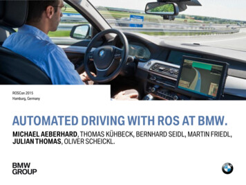
IntroductionApplication Examples 7Plant modelling– Modelling of nonlinear dynamic systems(continuous-time, discrete-time, hybrid)– Analyses of dynamic systems (pre-development)– Optimization of dynamic systems (system design) Design of embedded systems– Model-based software development– Automatic code generation (software andprogrammable hardware) Model-based testing– Open- and closed-loop testing of plant model andcontrol software– Formal methods for software verification– Hardware in the loop testingwww.mathworks.com/company/user stories/Basics of Simulink
Simulink – BasicsLaunching Simulink8Starting SimulinkBasics of Simulink
Simulink – BasicsSimulink Library Browser9Basics of Simulink
Simulink – BasicsFinding Blocks10Basics of Simulink
Simulink – BasicsGetting Help11123Basics of Simulink
Simulink – BasicsDemonstration of Model ElementsBasics of Simulink12
Simulink – BasicsSummary – Using Blocks and SignalsAdding Blocks: Drag and drop a block from the Simulink library into theblock diagram Copy a block inside the block diagram by dragging itwhile holding the right mouse key Click into the block diagram and start to enter the nameof the block (R14b)Connecting Blocks: Draw a line from the outport of one block to the inport ofa second block using the left mouse key To connect a block to a line, draw a line from the inport ofthe block backwards to the line to connect to. To quick connect two blocks, click on the outport of thefirst block and the inport of the second block whilekeeping the CRTL-key pressed Click the suggested connection lines (R14b)Basics of Simulink13
Simulink – BasicsSimulation Data Inspector14Basics of Simulink
OutlineSimulink and Stateflow15Basics:1) Simulink Basics Continuous Models Discrete Models Subsystems Signals2) Stateflow Flow Charts State Charts EventsAdvanced:1) Libraries and Model Reference2) Style Guidelines3) Model Advisor4) Report Generator and Model Comparison5) Integrating C Code using the Legacy Code Tool6) MATLAB Coder, Simulink Coder, Embedded CoderBasics of Simulink
Simulink – Continuous SystemsModeling Continuous Systems Engine provides variable-step and fixed-step ODE solversBlock Diagram representation of dynamic systemsBlocks define governing equationsSignals are propagated between blocks over time Remeber MuPad: Exercise: Create a mass-spring-damper systemin Simulink𝑚𝑥 b𝑥 𝑘𝑥 0,x 0 0, 𝑥 0 1, 𝑚 10, 𝑏 1, 𝑘 10Basics of Simulink16
Simulink – Continuous SystemsAlgebraic Loops Error because of Direct Feedthrough––Block input depends directly on its own outputE.g.: Gain, Product, Sum/Subtract, Transfer Fcn Recommended solution: use Delay, Integrator orother history related block Alternative, but bad solution:reduce diagnostics settings andleave solving up to Simulinkengine (not recommended!!)Basics of Simulink17
Simulink – Continuous SystemsSolver Solver?–– 18Determines solution at current time stepDetermines the next simulation time stepSolver options:Fixed-Step Ode1 Ode2 Ode3 Ode4 Ode5 Ode8Basics of SimulinkVariable-Step Ode45 Ode23 Ode113 Ode15s Ode23s Ode23t Ode23tb
Simulink – Continuous SystemsFixed-step SolverBasics of Simulink19
Simulink – Continuous SystemsVariable-step SolverBasics of Simulink20
Simulink – Continuous SystemsVariable-step SizeMax step size is the largesttime step that the solver cantake (‘auto’ means 50 steps)Basics of Simulink21
Simulink – Continuous SystemsDemo: Importing and Exporting DataBasics of Simulink22
Simulink – Continuous SystemsImporting Data into SimulinkIN Requires vector of time along with input valuesinput( t, u1 un ) defined configuration parametersCONSTANT Changeable on the highest hierarchy level Tunable with parameter objectsFROM WORKSPACE Requires vector of time along with input valuesinput( t, u1 un ) defined a workspace variableFROM FILE Requires vector of time along with input valuesinput( t, u1 un ) defined in a given mat fileBasics of Simulink23
Simulink – Continuous SystemsExporting Data to MATLAB WorkspaceOUT Saves all outputs together in one variable, defined in theconfiguration parametersTO WORKSPACE Saves the output data in a variable to the workspace,defined in the block parametersTO FILE Saves the output data in a .mat fileBasics of Simulink24
Simulink – Continuous SystemsExchanging Data with MATLAB WorkspaceFor IN and OUT blocks variables must bedefined in Configuration ParametersBasics of Simulink25
Simulink – Continuous SystemsMATLAB Embedded Subset of MATLAB for code generationCan be used for direct generation ofsource code out of MATLAB as well as inSimulink MATLAB Function blocksEnables user to reuse his MATLAB codein SimulinkTo call unsupported functions useeml.extrinsic or coder.extrinsic(leads to significantly reducedperformance!!!)Basics of Simulink26
Simulink – Continuous SystemsModel and Block CallbacksBasics of Simulink27
Simulink – Continuous SystemsCallback Functions28Common tasks you can achieve by using callback functions include: Loading variables into the MATLAB workspace automatically when youopen your Simulink model Executing a MATLAB script by double-clicking on a block Executing a series of commands before starting a simulation Executing commands when a block diagram is closedLoadInitializeStartModel CallbackContinueStopCloseHelp CallbackFunctionsBasics of SimulinkBlock Callback
OutlineSimulink and Stateflow29Basics:1) Simulink Basics Continuous Models Discrete Models Subsystems Signals2) Stateflow Flow Charts State Charts EventsAdvanced:1) Libraries and Model Reference2) Style Guidelines3) Model Advisor4) Report Generator and Model Comparison5) Integrating C Code using the Legacy Code Tool6) MATLAB Coder, Simulink Coder, Embedded CoderBasics of Simulink
Simulink – Discrete SystemsDemo: Creating a counter30Exercise: Create a Stop Watch Combine counters to a stop watch Show tenth seconds, seconds, minutes and hours Reduce simulation speed to soft realtimeBasics of Simulink
Simulink – Discrete SystemsMultirate Systems31 Systems with signals that are sampled atdifferent rates Use for discrete or hybrid systems To connect system use rate transition blocks Specify specific sampling rate by variable ateach in and out port Different sample times need to be aninteger multiple of the highest (global)sampling rate Sample Time Colors- fastest discrete sampling time is displayedin redBasics of Simulink
OutlineSimulink and Stateflow32Basics:1) Simulink Basics Continuous Models Discrete Models Subsystems Signals2) Stateflow Flow Charts State Charts EventsAdvanced:1) Libraries and Model Reference2) Style Guidelines3) Model Advisor4) Report Generator and Model Comparison5) Integrating C Code using the Legacy Code Tool6) MATLAB Coder, Simulink Coder, Embedded CoderBasics of Simulink
Simulink – SubsystemsSubsystems 33Why?–––Reduce blocks displayed in a model windowKeep functionally related block togetherEstablish hierarchical block diagramBasics of Simulink
Simulink – SubsystemsCreating Subsystems 34Context menu - Create SubsystemSubsystem portsInside a subsystemBasics of Simulink
Simulink – SubsystemsAtomic Subsystems35 Represent non-virtual systems within another system Have their own sampling rate Have their own code generating characteristics Have their own execution order numberBasics of Simulink
Simulink – SubsystemsMasking Subsystems36 Mask - Encapsulation with a UI Provides– Mask icon displaymasking– Block description– Parameter dialog prompt– Custom block help textmaskBasics of Simulink
OutlineSimulink and Stateflow37Basics:1) Simulink2) StateflowAdvanced:1) Libraries and Model Reference2) Style Guidelines3) Model Advisor4) Report Generator and Model Comparison5) Integrating C Code using the Legacy Code Tool6) MATLAB Coder, Simulink Coder, Embedded CoderBasics of Simulink
Simulink – Libraries and Model ReferenceUser Libraries Collection of reusable blocks Prototype block vs Reference block Propagation of changes to Library– Discard– Push Library Links– Disable link– Restore link– Break link Other features– Display in Simulink Library Browser– Add documentationBasics of Simulink38
Simulink – Libraries and Model ReferenceModel Referencing One model in another- parent and referenced model Advantages:– Componentization/Modularization– IP protection– Multiple referencing– AccelerationBasics of Simulink39
OutlineSimulink and Stateflow40Basics:1) Simulink Basics Continuous Models Discrete Models Subsystems Signals2) Stateflow Flow Charts State Charts EventsAdvanced:1) Libraries and Model Reference2) Style Guidelines3) Model Advisor4) Report Generator and Model Comparison5) Integrating C Code using the Legacy Code Tool6) MATLAB Coder, Simulink Coder, Embedded CoderBasics of Simulink
Simulink – SignalsVectors41 Matrix and Vector operations possible Mux block to compose vector Demux block to extract from signal Increase simulation performanceBasics of Simulink
Simulink – SignalsBusses42 Graphical grouping of signals to a hierarchical bus signal Bus creators to create a bus from signal and busses Bus selector to select single signals or whole sub-busses Bus Objects can be specifiedBasics of Simulink
Simulink – SignalsSimulink Model Explorer43Basics of Simulink
Simulink – SignalsSimulink Data Objects 44Simulink Parameter Object Var Simulink.Parameter Simulink Signal Object Var Simulink.Signal Simulink Bus Object– Use Bus editorBasics of Simulink
Simulink – SignalsSignal Logging45ConfigurationParametersSignal ContextMenuBasics of Simulink
OutlineSimulink and Stateflow46Basics:1) Simulink Basics Continuous Models Discrete Models Subsystems Signals2) Stateflow Flow Charts State Charts EventsAdvanced:1) Libraries and Model Reference2) Style Guidelines3) Model Advisor4) Report Generator and Model Comparison5) Integrating C Code using the Legacy Code Tool6) MATLAB Coder, Simulink Coder, Embedded CoderBasics of Simulink
StateflowWhat is Stateflow?47 Stateflow is a blockset for Simulink Stateflow extends the signal flow paradigm of Simulink with state machines Stateflow supports flow charts and state charts Charts can be implemented using C or MATLAB as action language Stateflow supports Mealy and Moore charts Events are available for asynchronous communication Stateflow is fully integrated with Simulink Stateflow supports embedded code generationBasics of Simulink
StateflowWhen to use Stateflow?48na 0006: Guidelines for mixed use of Simulink and Stateflow If the function primarily involves complicated logical operations, use Stateflow diagrams.Use Stateflow diagrams toimplement modal logic, where the control function to be performed at the current time depends on a combination of pastand present logical conditions. If the function primarily involves numerical operations, use Simulink features.na 0007: Guidelines for use of Flow Charts, Truth Tables and State Machines If the primary nature of the function segment is to calculate modes of operation or discrete-valued states, use statecharts. Some examples are:- Diagnostic models with pass, fail, abort, and conflict states- Model that calculates differentmodes of operation for a control algorithm If the primary nature of the function segment involves if-then-else statements, use flowcharts or truth tables.Basics of Simulink
OutlineSimulink and Stateflow49Basics:1) Simulink Basics Continuous Models Discrete Models Subsystems Signals2) Stateflow Flow Charts State Charts EventsAdvanced:1) Libraries and Model Reference2) Style Guidelines3) Model Advisor4) Report Generator and Model Comparison5) Integrating C Code using the Legacy Code Tool6) MATLAB Coder, Simulink Coder, Embedded CoderBasics of Simulink
Stateflow – Flow ChartsDemo: Flow Graph Soda Machine Flow Graphs have no action or information in state. Everything is done ontransitions. First condition [a b], then action {c 0;} Demo: A soda machine provides coke, orange juice and water. The user entersthe corresponding number. The machine puts out a can with the drink.Basics of Simulink50
Stateflow – Flow ChartsBasic ingJunctionTransitionsJunctionBasics of Simulink
Stateflow – Flow ChartsHints First Condition, then Action! Double Click keeps buttonspressed52Basics of Simulink
Stateflow – Flow ChartsDefining Chart Data53Basics of Simulink
Stateflow – Flow ChartsGuidelines for Creating Flow Charts The execution has only one entry point! The execution has only one termination point! The execution can always reach the termination point! The flow never backtracks!Basics of Simulink54
OutlineSimulink and Stateflow55Basics:1) Simulink Basics Continuous Models Discrete Models Subsystems Signals2) Stateflow Flow Charts State Charts EventsAdvanced:1) Libraries and Model Reference2) Style Guidelines3) Model Advisor4) Report Generator and Model Comparison5) Integrating C Code using the Legacy Code Tool6) MATLAB Coder, Simulink Coder, Embedded CoderBasics of Simulink
Stateflow – State ChartsState Charts56 State charts have a internal behavior andinternal data Actions can be performed on entry, duringresidence in the state and on exit A state can perform a self transition A state can be either active or passiveBasics of Simulink
Stateflow – State ChartsMealy Charts, Moore Charts and Stateflow Mealy charts perform actions on transition Moore charts perform actions in states Using the Model Explorer, state charts canbe configured to Mealy, Moore or Classic See sf seqrec for example Choosing Mealy, Moore or Classic as charttype effects compatibility of otherMathWorks tools (e.g. Simulink CodeInspector)MATLAB help - Stateflow - Chart Programming - Supported State Machines - ConceptsBasics of Simulink57
Stateflow – State ChartsAction Language MATLAB vs. C Stateflow supports MATLAB and C as actionlanguage (selected via Model Explorer) MATLAB as action language supports autocorrection For embedded code generation, C as actionlanguage is easier to reviewMATLAB Help - Stateflow - Chart Programming - Chart Programming Basics - Concepts - Differences Between MATLAB and C as ActionLanguage SyntaxMATLAB Help - Stateflow - Chart Programming - Chart Programming Basics - Concepts - ActionLanguage Auto CorrectionBasics of Simulink58
Stateflow – State ChartsDemo: Autopilot Mode ControlBasics of Simulink59
Stateflow – State ChartsExecution Ordertrue60executesdoes not executeBasics of Simulinkfalse
Stateflow – State ChartsParallel Charts and Hierarchical ChartsBasics of Simulink61
Stateflow – State ChartsExercise: Elevator62 States: InitialState, Stopped, Up, Down Doors may only open when elevator is stopped Inputs: Height, Request Outputs: Command, Doors Doors: close false, open true Command: up 1, down 2, stop 3 Height of each floor 3Basics of Simulink
OutlineSimulink and Stateflow63Basics:1) Simulink Basics Continuous Models Discrete Models Subsystems Signals2) Stateflow Flow Charts State Charts EventsAdvanced:1) Libraries and Model Reference2) Style Guidelines3) Model Advisor4) Report Generator and Model Comparison5) Integrating C Code using the Legacy Code Tool6) MATLAB Coder, Simulink Coder, Embedded CoderBasics of Simulink
Stateflow – EventsDefinition64 Events are used for asynchronouscommunication Events can be directed or broadcast Events in Stateflow can be defined as input,local or output using the Model Explorer Events interact with state charts (triggeractions in parallel states), Simulink TriggeredSubsystems and Simulink Function-CallSubsystems Events can be used on transitions and withinstatesMATLAB Help - Stateflow - Chart Programming - Chart Simulation Semantics - Concepts - HowEvents Drive Chart ExecutionBasics of Simulink
Stateflow – EventsExample: sf car65MATLAB Help - Stateflow- Getting Started with Stateflow - About Event-DrivenSystem Modeling - Anatomy of a Stateflow ChartBasics of Simulink
Stateflow – EventsDirect and qualified event broadcast66Qualified BroadcastDirect BroadcastBasics of Simulink
Stateflow – EventsTemporal Logic67Enables time-dependent logic based on event countsTemporal logic operators: at(n,event): true at the nth trigger of event every(n,event): true at every nth trigger of event after(n,event): true after the nth trigger of event before(n,event): true before the nth trigger of eventCan be applied as an eventor condition after(5,tick) [after(5,tick)]MATLAB Help - Stateflow - Chart Programming - Syntax for States and Transitions - Control ChartExecution Using Temporal LogicBasics of Simulink
StateflowFunctions and Keywords – SummaryState action keywords entry / en – Perform actions upon state entry during / du – Perform actions when staying in state exit / ex – Perform actions upon state exit on – Perform actions upon specified event bind – Bind events to a state *Note, you can combine entry, during, and exit actions with thesyntaxen, du:Temporal logic operators at(n,event) – true at the nth trigger of event every(n,event) – true at every nth trigger of event after(n,event) – true after the nth trigger of event before(n,event) – true before the nth trigger of event temporalCount(event) – returns n at the nth trigger of event,otherwise returns 0In these operators, you can also use the keyword sec in place of anevent. This keyword makes these operators count elapsed simulationtime instead of the number of events.State detection enter(state) – Event occurs when the specified state is entered. exit(state) – Event occurs when the specified state is exited. in(state) – Returns true when state is active68Data change detection change(data) – Event occurs when the specified data is written. hasChanged(data) – True when changes have been made todata since the last time step hasChangedFrom(data,x) – True when changes have beenmade to data since the last time step, and last time step value wasx hasChangedTo(data,x) – True when changes have been madeto data since the last time step, and current time step value is xBuilt-in temporal events tick – Event occurs whenever the Stateflow chart is updated. wakeup – Same as tickLocal state data StateA.a – Accesses local data a defined in state StateA fromoutside of StateA StateA.e – Broadcasts local event e defined in state StateAfrom outside of StateAEvent broadcast StateA.e – Qualified event broadcast send(e,StateA) – Directed event broadcast e – Unqualified event broadcastBasics of Simulink
OutlineSimulink and Stateflow69Basics:1) Simulink Basics Continuous Models Discrete Models Subsystems Signals2) StateflowFlow Charts State Charts EventsAdvanced:1) Libraries and Model Reference2) Style Guidelines3) Model Advisor4) Report Generator and Model Comparison5) Integrating C Code using the Legacy Code Tool6) MATLAB Coder, Simulink Coder, Embedded CoderBasics of Simulink
Modeling GuidelinesIncreasing Model Quality70Help Simulink Modeling GuidelinesBasics of Simulink
OutlineSimulink and Stateflow71Basics:1) Simulink Basics Continuous Models Discrete Models Subsystems Signals2) Stateflow Flow Charts State Charts EventsAdvanced:1) Libraries and Model Reference2) Style Guidelines3) Model Advisor4) Report Generator and Model Comparison5) Integrating C Code using the Legacy Code Tool6) MATLAB Coder, Simulink Coder, Embedded CoderBasics of Simulink
Model AdvisorSimulink Model Advisor72Basics of Simulink
OutlineSimulink and Stateflow73Basics:1) Simulink Basics Continuous Models Discrete Models Subsystems Signals2) Stateflow Flow Charts State Charts EventsAdvanced:1) Libraries and Model Reference2) Style Guidelines3) Model Advisor4) Report Generator and Model Comparison5) Integrating C Code using the Legacy Code Tool6) MATLAB Coder, Simulink Coder, Embedded CoderBasics of Simulink
Report Generator and Model ComparisonAutomatic Report GenerationBasics of Simulink74
Report Generator and Model ComparisonCompare XML FilesBasics of Simulink75
OutlineSimulink and Stateflow76Basics:1) Simulink Basics Continuous Models Discrete Models Subsystems Signals2) Stateflow Flow Charts State Charts EventsAdvanced:1) Libraries and Model Reference2) Style Guidelines3) Model Advisor4) Report Generator and Model Comparison5) Integrating C Code using the Legacy Code Tool6) MATLAB Coder, Simulink Coder, Embedded CoderBasics of Simulink
Integrating C Code using the Legacy Code ToolIntroducing S-Functions 77S-Functions are used for:– Hiding information about a models content (IPR)– Speeding up simulation– Integrating external functions written in C S-Functions can be created by Block Context Menu, by Legacy Code Tool, by SFunction Builder or they can be written by hand (template available) S-Functions always consist of two elements:A .mexw32 file containing the compiled modelA S-Function Block calling the .mexw32 file In most cases S-Function blocks are masked to increase usabilityBasics of Simulink
Integrating C Code using the Legacy Code ToolDemo: Legacy Code Tool LCT only creates a wrapper, which will beremoved at code generation Simple way to integrate C code in Simulink In MATLAB use ceval to integrate codeHelp „Integrating Existing CFunctions into Simulink Models withthe Legacy Code Tool”Basics of Simulink78
OutlineSimulink and Stateflow79Basics:1) Simulink Basics Continuous Models Discrete Models Subsystems Signals2) Stateflow Flow Charts State Charts EventsAdvanced:1) Libraries and Model Reference2) Style Guidelines3) Model Advisor4) Report Generator and Model Comparison5) Integrating C Code using the Legacy Code Tool6) MATLAB Coder, Simulink Coder, Embedded CoderBasics of Simulink
MATLAB Coder, Simulink Coder, Embedded CoderMATLAB CoderBasics of Simulink80
MATLAB Coder, Simulink Coder, Embedded CoderSimulink Coder and Embedded CoderBasics of Simulink81
82Summary Simulink is a graphical modeling environment based on MATLABSimulink is fully integrated in MATLAB environmentSimulink can be used to model continuous, discrete and hybrid sytsemsIn addition, Simulink is a graphical programming language for embeddedsystemsSimulink interacts with real hardware for Hardware In The Loop orProcesoor in the Loop setups, as well as for test beds and laboratory setupsBasics of Simulink
83ContactContact for further information or feedback about this course:Dipl.-Ing. Markus HornauerInstitute of Flight Systems DynamicsBoltzmannstr. 1585748 Garching, GermanyTel: 49 (0)89 289 16047Fax: 49 (0)89 289 16058Email: markus.hornauer@tum.desamoconsult GmbHsafety I modeling I consultingMarkus HornauerHigh Integrity Systems EngineerFranzösische Str. 13-14D – 10117 Berlin 49 151 23506683www.samoconsult.deBasics of Simulinkmarkus.hornauer@samoconsult.de
Basics of Simulink Simulink –Basics Summary –Using Blocks and Signals 13 Adding Blocks: Drag and drop a block from the Simulink library into the block diagr