Transcription
BULLETIN No. 912 –MANHOLE & PUMP STATIONINSTALLATION GUIDEASTM F1759/ ASTM D2321High Density Polyethylene Manholes & Pump StationsUSAw w w.PlassonUSA.comPlasson USA 305 N 7th St., Corsicana, TX 75110 800-241-4175Stafford, TX Missoula, MT Corsicana, TXwww.PlassonUSA.comUSA1
2USAwww.PlassonUSA.com
TABLE OF CONTENTSSPIROLITE MANHOLE INSTALLATIONGUIDELINES - pg. 2-399 Introduction99 HandlingMANHOLE INSTALLATION - pg. 3-6999999999999FoundationBackfill and CompactionConcrete Anti-Flotation CollarsFlowable FillsFinishing Manhole to GradeVehicular Loads Require ReinforcedConcrete Manhole CapsThis bulletin is intended to be used as a guide to support the designer in the use of Spirolite pipe. It is not intended to be used in the place of aprofessional design engineer. The information contained herein cannot be guaranteed because the conditions of use are beyond our control.The user of this bulletin assumes all risk associated with its use.www.PlassonUSA.comUSA1
ing a safety harness attached to a fallwalls SPIROLITEof the manholemay be slippery,MANHOLEorking inside the manhole. All OSHA,INSTALLATION GUIDELINESprocedures must be followed includinge of gas detection equipment to proveaccordance with local, state, and OSHA- Trench excavation, including pl- Entry and egress of trenches, pi- Heavy equipment operation! WARNINGHandling!Safe includinghandlingthoseinstructionsare providedwiPlasson USA recommends that all entries into Spirolite manholes,containing ladders,bethese instructionsmay resultin ofsevere imade using a safety harness attached to a fall protection system.The standing surfacesand wallsthe manhole may be slippery, particularly when wet. Use dueandcautionwhen workinginside the manhole.handlingany IndustrialPipe Fittingsnd permanentsupport under and around theAll OSHA, local, and other applicable confined space entry procedures must be followed including thehandling be acquainted with the Hanation andbackfill materialsis necessaryto of gas detectiontheirimplementationof a three-mancrew and useequipment to prove the atmosphere safe.edures should be strictly followed duringoles. INTRODUCTIONAll construction must be done in, includinglimitedinstallationto:The key butto anotsuccessfulis achieving stableracing,and trenchshieldsandsheathingpermanent supportunder andaround the manhole.nholesUniform and proper placement of the foundation and backfillFig. 8-1. Placing Manholematerials is necessary to obtain permanent support. Allapplicable safety procedures should be strictly followedduring handling and installation of Spirolite manholes. Allconstruction must be done in accordance with local, state,OSHAbuttonotlimited to:ent ollow99 Trenchexcavation,includingplacement of bracing,, or propertydamage.Priorto off-loadingsheathingandtrenchshieldss imperative that all personnel involved intions. 99 Entry and egress of trenches, pipes, and manholes99 HeavyequipmentoperationFig. 8-2.ManholeTrenchin LandfillFIGURE 1A: PLACING MANHOLESHANDLINGSafe handling instructions are provided with each shipmentof pipe and manholes. Failure to follow these instructionsmay result in severe injury, death, or property damage. Priorto off-loading and handling any Plasson USA structures, it isimperative that all personnel involved in their handling beacquainted with the Handling Instructions.FIGURE 1B:MANHOLE TRENCH IN LANDFILL2USAThe delivery vehicle and lifting equipment must be parked onlevel ground with stabilizers fully extended and set. Parkingbrakes must be set and wheels chocked where applicable.The unloading equipment should be inspected for conditionand lifting capacity before use. The structure should be liftedwww.PlassonUSA.com
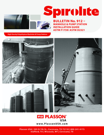
with a crane or backhoe using slings of sufficientcapacity to safely handle the load.The following should be met:99 Use only web style slings when lifting thestructures. Do not use wire rope or other devicesthat may cut into the lifting lugs or provideinsufficient force distribution.Structures shall be moved using the lifting lugsconnected to the manhole wall. All lugs are equallyspaced around the circumference. A web style strap,99 Do not sling by fewer lugs than those providedsuch as nylon, shall be connected to each lug on oneon the structure.end and held together with a hook on the other end (as99 Do not lift structure when containing fluid or anyillustrated in Fig. 1), taking care to distribute the loadThedeliveryvehicleandliftingequipmentmust be parked on level ground with stabilizers fullyothermaterials.equally between all lugs. When standing the structureextended and set. Parking brakes must be set and wheels chocked where applicable. The unloadingupright, do not lift by lifting lugs. Wrap strapsaround99 forDonot andstandunder,or Thearoundequipmentshould be inspectedconditionliftingon,capacitybefore use.structurestructureshould beliftedwithwitha crane or backhoe ad.the structure and use the lugs as strap stops.Liftwhile it is being lifted.the straps. Once the structure is verticallyStructures“righted”,shall be moved using the lifting lugs connected to the manhole wall. All lugs are equallyspaced around the circumference. A web style strap, such as nylon, shall be connected to each lugthen the lugs may be used for lifting.on one end and held together with a hook on the other end (as illustrated in Fig. 1), taking care todistribute the load equally between all lugs. When standing the structure upright, do not lift by liftinglugs. Wrap straps around the structure and use the lugs as strap stops. Lift with the straps. Once thestructure is vertically "righted", then the lugs may be used for lifting. The following should be met:x Use only web style slings when lifting the structures. Do not use wire rope or other devicesthat may cut into the lifting lugs or provide insufficient force distribution.x Do not sling by fewer lugs than those provided on the structure.x Do not lift structure when containing fluid or any other materials.x Do not stand on, under, or around structure while it is being lifted.MANHOLE INSTALLATION! WARNING !Consult the appropriateManholeauthoritieson trench construction requirements.InstallationWarningTake all safety precautions when working in or near a trench.Plasson USA recommendationsfor the installation of manholessatisfy the design assumptionsgiven in Section 4.2 of ASTM F1759. Plasson USA recommendsthat the manholes be placed ona stable base and embeddedwith a compacted coarse-grainedembedment material that extendsradially at least 3.5 ft from theperimeter of the manhole or toundisturbed situ soil (whichever isgreater) and for the full height of themanhole. Direct installation in newor active sanitary landfills or otherfills subject to large settlementsrequire special considerationsoutside the scope of theserecommendations. Figure 2 showsPlasson USA’ recommendations.www.PlassonUSA.comConsult the appropriate authorities on trench construction requirements. Take all safetyprecautions when working in or near a trench.Industrial Pipe Fittings’ recommendations for the installation of manholes satisfy the designassumptions given in Section 4.2 of ASTM F 1759. Industrial Pipe Fittings recommends that themanholes be placed on a stable base and embedded with a compacted coarse-grained embedmentmaterial that extends radially at least 3.5 ft from the perimeter of the manhole or to undisturbed inFIGURE 2: TYPICAL INSTALLATION RECOMMENDATIONSFOR SPIROLITE MANHOLES DEWATERING3.5’ min.The manhole trench must be dry during installation. Dewater by installingdeep wells, sumps, well points, or other methods appropriate for theparticular site. Maintain dewatering until completion of backfilling toprevent flotation during construction.USA3
DewateringThe manhole trench must be dry during installation. Dewater by installing deep wells, sumps, wellFOUNDATIONpoints,or other methods appropriate for the particular site. Maintain dewatering until completion ofThe manholeshould beflotationinstalled ona stablefoundation. All largebackfillingto preventduringconstruction.rocks and clumps should be removed from the trench bottom. Thefoundation should consist of a minimum of 8" of Class I material (asFoundationdefined by ASTM D 2321) compacted to a minimum of 95% StandardThe manhole should be installed on a stable foundation. All large rocks and clumps should beProctor (as defined by ASTM D 698). Placement on a concrete slabremovedfrom the trench bottom. The foundation should consist of a minimum of 8" of Class Ifoundation is also acceptable. In unstable insitu soils, a sub-foundationmaterialdefinedbyaASTMD 2321)to a minimum of 95% Standard Proctor (asmay be (asrequiredto obtainstable trenchbottom.compactedThe sub-foundationdefinedASTM DPlacementonoraotherwiseconcreteunstableslab foundation is also acceptable. In unstablecan bebyconstructedby 698).removingweak organicinsitua sub-foundationmaycompactedbe requiredto obtain a stable trench bottom. The sub-foundationsoilssoils,and replacingthem with stable,materials.can be constructed by removing weak organic or otherwise unstable soils and replacing them withstable,compactedmaterials.BACKFILLAND COMPACTIONPlasson USA recommends the use of Class I or II material asFIGURE 3A: PLACE MANHOLEdefinedby ASTM D2321 for embedment of the manhole. Place inON STABLE FOUNDATIONFig.density8-4. Place Manholeon Stable Foundationlifts not exceeding 8" and mechanically compact to thespecified by the Engineer or 90% Standard Proctor (95% understreets), which ever is higher. Compacted backfill mustBackfillextend toand Compactionthe trench wall or undisturbed soil. This distance from themanhole Pipe Fittings recommends the use of ClaIndustrial(outside surface of the riser) to the trench wall must be forat least3.5embedmentof the manhole. Place in lifts notfeet. See Figure 2.density specified by the Engineer or 90% Standahigher. Compacted backfill must extend to the trenWhen lateral pipe connections enter the manhole, the embedmentthe manhole (outside surface of the riser) to the trenrequirements for the pipe located within the backfill zone of themanhole must meet or exceed both the minimum requirements forWhen lateral pipe connections enter the manhole, tthe manhole, as well as, the minimum requirements for the pipe.CONCRETE ANTI-FLOTATION COLLARSWhen a concrete collar and anchor connection ring is used to resistflotation, compacted foundation material should extend aboveanchorconnectionring onto thebottomFoundationof the concrete collarFig.asFig.the8-4.PlaceManholeStableshown in Figures 3 & 4.FIGURE 3B:EmbedmentMEASURINGDensity8-5. MeasuringEMBEDMENT DENSITYBackfill and CompactionFLOWABLEFILLSIndustrialPipeFittings recommends the use of Class I or II material as defined by ASTM D2321for Whenembedmentof the flowablemanhole.Placein liftsincludingnot exceeding8" andmechanicallycompactplaced correctly,backfillmaterial,materials suchas concrete,cementatiousgrout toor thecontrolleddensity byfill (CDF),can provideorreliablesupport.Precautionsbe streets),taken to avoidbucklingdensityspecifiedthe Engineer90%manholeStandardProctor(95% mustunderwhichever isand/orCompactedfloating the manholeof theflowablefill. Theseprecautionsmay includefilling themanholehigher.backfillduringmustplacementextend totrenchwall orundisturbedsoil. Thisdistancefromwater, (outsideplacing flowablefill instruttinginsidewallof themanhole.Owneror Owner’sEngineer8-3.the withmanholesurfaceoflifts,the andriser)to thethetrenchmustbe atTheleast3.5 feet.See Figureshould review and approve the installation procedure for each flowable backfill application. Plasson USA disclaimsany lateraland all liabilityfor manholes thatarethedamagedduringthethe embedmentplacement of flowablebackfill. for the pipe locatedWhenpipe nUSA.com
shown in FiguresWhen8-6 and8-7. SeeChapter7, “Anti-FlotationOptions".a concretecollarand anchorconnection ringis used to resist flotation, compactedmaterial should extend above the anchor connection ring to the bottom of the concretshown in Figures 8-6 and 8-7. See Chapter 7, “Anti-Flotation Options".FIGURE 4:SPIROLITEMANHOLEINSTALLATIONWITH ANTIFLOTATION COLLARFig. 8-6 SPIROLITE Manhole Installation with Anti-Flotation CollarFINISHING MANHOLE TO GRADEFig. 8-6 SPIROLITE Manhole Installation with Anti-Flotation CollarFIGURE 5: DETAIL OF CONCRETEANTI-FLOTATION COLLAR INSTALLATIONManholes with cone tops can, in most cases, befield adjusted to accommodate the final grade.The riser may be cut to remove excess riser height,provided it is not obstructed by a ladder or otherappurtenance and is cut even and square. The conetop may then be placed on the riser. A concretegrade ring or course of bricks may be placed on thecone's shoulder to support the cast iron ring and tomake any final grade adjustments. See AppendixC,Fig. 8-7 Detailof Concrete Anti-flotation Collar Installation“Spirolite Manhole Cone Installation.”Fig. 8-7 Detail of Concrete Anti-flotation Collar InstallationManholes with flat tops are manufactured to the appropriate height specified by the Owner or Owner’s Engineerto accommodate the final field grade required. The height of such manholes cannot be easily field adjusted.Before ordering the manhole, the Owner should verify the correct height.VEHICULAR LOADS REQUIRE REINFORCED CONCRETE MANHOLE CAPSWheel loads from cars, trucks and other vehicles can produce significant force on buried manholes and thereforemust be considered in design. The most common loading used for design is the H-20 highway loading. The AmericanAssociation of State Highway and Transportation Officials (AASHTO) publishes wheel loads for the standard H-20highway loading.www.PlassonUSA.comUSA5
! WARNING !When Spirolite manholes are installed in streets, under pavement, or where there is vehicular traffic, aconcrete cap must be placed over the manhole to provide inde
defined by ASTM D 2321) compacted to a minimum of 95% Standard Proctor (as defined by ASTM D 698). Placement on a concrete slab foundation is also acceptable. In unstable insitu soils, a sub-foundation may be required to obtain a stable trench bottom. The sub-foundation can be constructed by removing weak organic or otherwise unstable soils and replacing them with stable, compacted