Transcription
Agilent TechnologiesPulsed Measurements withthe Agilent 8720ES and 8753ESNetwork AnalyzersProduct Note
IntroductionHigh-performance vector network analyzers are used tocharacterize the frequency responses of various RF andmicrowave components. While most network analyzersare used to measure continuous signals, some users havea need to pulse the RF signal on and off. The need forpulsed signals arises for various reasons. It might bebecause the total power input to the device under testmust be limited to prevent overheating, or because thecomponent will only operate under pulsed conditions, orbecause the component behaves differently in responseto pulses than it does to steady state inputs. Whateverthe reason, pulsed RF creates a unique set of conditionsthat must be addressed in order to produce reliablemeasurement results.It is commonly presumed that only network analyzerssuch as the Agilent 8510C or the 85108A that incorporate sophisticated timing circuits, dual reference channels, and wide IF bandwidths are suitable formeasurements of pulsed systems. However, the aim ofthis product note is to show that under certain conditions, network analyzers such as the 8720ES and 8753EScan produce good results at a much lower cost. Theprinciples in this product note apply to either model,and to some earlier models as well; for brevity we willrefer only to the 8720ES throughout the rest of thisproduct note.In general, for a standard network analyzer to be able tomake pulsed measurements, there are three conditionsthat must be met. The first condition is that the RFsource must be externally modulated, since a standardnetwork analyzer lacks any modulating circuitry. Thesecond condition is that if the pulse is a single or randomly timed pulse, it must exceed a width of 400microseconds. Also for this case, the user must supplyexternal triggering circuitry with variable delay betweenthe trigger signal and the RF pulse. The third conditionis that if the RF signal is a continuous pulse train, theminimum pulse width must exceed 500 nanoseconds andthe pulse repetition frequency must be 20 Hz or greater.The reasons for these constraints will be explained later.(Note: the techniques described in this product notecannot determine the impulse response of a device.)2
Measurement theoryIn general two types of pulse measurements may bemade: Those with a pulse width greater than the network analyzer’s response time, and those with a pulsewidth less than the network analyzer’s response time.These will be designated as low PRF measurements andhigh PRF measurements, where PRF stands for pulserepetition frequency. Each of these conditions must betreated as a separate case, since each has its own uniquerequirements.Low PRF measurementsEvery network analyzer has a sample response time thatdepends upon fixed internal characteristics such as CPUspeed, and variable characteristics such as the IF bandwidth of the system. It is characteristic of the digital filtering used in the 8720E and 8753E that wide IFbandwidths result in faster sample times, while narrowIF bandwidths improve dynamic range.If a given pulse is wider than the minimum analyzerresponse time, and the proper timing is establishedbetween the external signal that triggers the analyzerand the signal that triggers the pulse itself, we can beguaranteed that a valid measurement point will result.This is because during the entire time the analyzer issampling, the RF signal is on. We define this condition tobe a low PRF measurement. Because the 8720ES triggers on a falling edge, the external trigger signal mustoften be inverted to generate this edge before the RFpulse appears. Also, it should be noted that the analyzerdoes not begin sampling until some time has elapsedafter the trigger signal has been received. Table 1 showsthe relationship between the IF bandwidth and the minimum pulse width and delay for the 8720ES when operating in the low PRF mode. Note that the trigger delayvaries slightly between instruments.Table 1. Using external triggering for low PRFIF BandwidthMinimum pulsewidth for a singlemeasurement point(milliseconds)Trigger delay(typical)1(milliseconds)6000 Hz0.400.703700 Hz0.530.703000 Hz0.600.701000 Hz1.100.70300 Hz3.200.70100 Hz8.900.7030 Hz32.00.7010 Hz1200.70Two types of low PRF measurements are possible. Thefirst type is commonly referred to as the pulse-profilemode of operation. In this mode the source is operatingat a CW frequency, and the analyzer is armed to trigger asweep. The RF signal is pulsed on after the sweep hasbeen triggered. Because the 8720ES does not containany circuits for controlling the delay between receipt ofa trigger and the start of a sweep, the user must providethis delay externally. If the pulse is wide enough thatseveral measurement points can be taken during a singlepulse, then we can see the shape of the pulse over timeas it is transmitted through the device under test (DUT).Each point represents the same frequency over time.This mode is useful for determining such things as pulsedroop. The reason specialized network analyzers such asthe 8530A have an advantage over the 8720ES in thismode is that their minimum pulse width is much narrower, 1 microsecond or less.The second type of low PRF measurement is commonlyreferred to as point-on-pulse mode. In this mode thesource is tuned, the RF pulsed on, and the analyzer isarmed to trigger on each individual pulse after a predetermined time delay. Each measurement point represents a different frequency. This mode is useful fordetermining the frequency response of the DUT when itcannot be powered up for long periods. Because the8720ES does not begin to sample instantly when a trigger signal is received, the user must provide anadjustable delay externally. Specialized network analyzers such as the 85108A have built in triggering circuitsto adjust the delay between the time the RF pulses onand the analyzer takes a measurement. The 85108A alsouses wideband detection instead of the narrowbanddetection used on the 8720ES, giving it an effective IFbandwidth of 1.5 MHz. This means the sample responsetime is much faster, which allows the user to sample atwidely variable times within pulses as narrow as 5microseconds.There is a third type of measurement known as peakresponse mode. This is when the pulse is narrower thanthe analyzer’s response time, but not so narrow that theanalyzer fails to register any signal. It may be consideredthe transition between low PRF and high PRF measurements. Because of the critical timing requirements, thismode is not recommended for the 8720E or 8753E.1. The digital IF takes several ADC samples before it starts taking the "real" data for the point. It uses these samples to compute the IF gain setting; it does this even if IF gain iscontrolled manually in the service menu. The most common value for this delay is 0.70 milliseconds, but some instruments exhibit delays of 0.81 or 1.00 milliseconds. There is noway to tell which is which, except by experiment. Once the trigger delay is determined, it is constant within a given instrument (i.e. there is no dependence on settings). The useris always safe by presuming a shorter delay than given in the table, however the minimum pulse width may have to be increased correspondingly to compensate for anydifference between the presumed delay time and the actual delay time.3
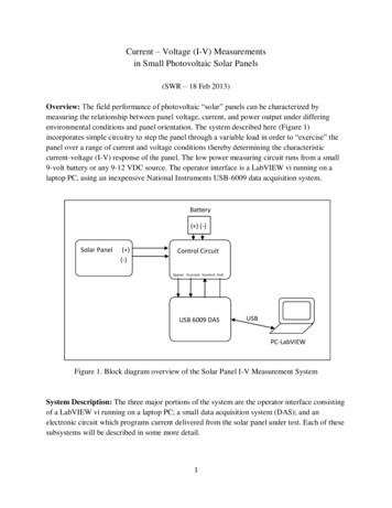
High PRF measurementsIf a given pulse is narrower than the minimum analyzerresponse time, it becomes impossible to measure a single pulse. We must restrict ourselves to measurementsof a pulse train. In order to understand how such measurements are possible, we must first have some fundamental understanding of how the analyzer treats anincoming signal. This will allow us to anticipate theinstrument’s response to the presence of a discontinuoussignal such as a pulse.Looking at Figure 1, we see that in a normal measurement, the source passes through the transfer switch,through the port 1 coupler, and out to the DUT attachedto port 1. Transmitted signals pass through the DUT,into port 2, through the port 2 coupler, and into samplerB. Reflected signals return into port 1 and pass throughthe port 1 coupler into sampler A. Signals that reach thesamplers are down-converted to an IF, filtered anddown-converted a second time to a 4 kHz IF. These signals are then digitized. After this step, all further signalprocessing is done digitally.Of all the elements in the signal path, it is the digital IFbandwidth filter which exerts the greatest influence overour pulsed signal. The IF bandwidth filter is a variablebandwidth filter, ranging from 10 Hz to 6 kHz. As theanalyzer sweeps in frequency, the IF bandwidth filtertracks along with the source, selecting only a narrowsegment out of the center of the IF signal bandwidth.The relationship between the bandwidth of this filterand the pulse repetition frequency (PRF) largely determines the response of the analyzer to a pulsed signal.Now consider the spectrum of a rectangular pulse train,as shown in Figure 2. This is a MatLab simulation of a4 kHz continuous-wave (CW) signal, modulated by a rectangular pulse train with a 200 Hz PRF and a 0.2 dutycycle. Duty cycle for our purposes is defined as:Duty Cycle Pulse Width / Pulse PeriodThis signal has already been downconverted to 4 kHzand is ready to enter the IF bandwidth (IFBW) filter.The left column of the figure shows the signal in thetime domain, while the right hand column shows the signal in the frequency domain. The first pair of diagramsshows the pulsed signal without any IFBW filtering.Notice that the presence of the modulating pulse transfers energy out of the central "carrier" frequency andspreads it into the sidebands. Multiple spectral lines arepresent, and viewed in the time domain the pulse retainsa rectangular shape as it passes through the analyzer.The analyzer responds to the pulse as you might expect;part of the time an RF signal is on, and part of the timethe signal is off. Notice that the spectral lines are spaced200 Hz apart, just equal to the PRF. Notice also that aswe move away from the center of the display, the firstminimum (or null) occurs at the fifth spectral line. Notcoincidentally, 1/5 equals our duty cycle (0.2). So, fromthe spectral display we can deduce the characteristics ofthe pulse train. These relationships hold true for anyrectangular pulse, regardless of frequency or duty cycle.Figure 1. Network analyzer block diagram4
The second pair of diagrams in Figure 2 shows the effectof a 3000 Hz IF bandwidth filter on the pulse. Noticethat many of the sidebands have been eliminated. Noticealso what has happened to the shape of the pulse in thetime domain.Figure 2. Effect of IF filtering on high PRF measurementsThe third pair of diagrams in Figure 2 shows the effectof a 1000-Hz IF bandwidth filter on the pulse. Only a fewspectral lines will fit within the bandwidth of the IFbandwidth filter. We know that there are an infinitenumber of spectral lines in the spectrum of any rectangular pulse; if we filter off all but a few of them with ourIF bandwidth filter, what has that done to the shape ofthe pulse? Look at the corresponding diagram in the leftcolumn. The pulse is becoming rounded and smoothed,so that it no longer has a definite beginning or end.Some signal is always present. Since a high PRF pulse isby definition too narrow for external triggering to beeffective, the analyzer responds to this signal as thoughthe S-parameter of the DUT is continuously varying asthe pulse amplitude varies. Clearly, this is an undesirableoperating condition.The fourth pair of diagrams in Figure 2 shows the effectof a 300-Hz IF bandwidth filter on the pulse. At this narrow IF bandwidth, only a single spectral line will fit within the filter bandwidth1, and the pulse appears as asingle, continuous frequency, but at a lower power level.Since this is the normal operating condition for a network analyzer, the analyzer responds normally, exceptthat we must account for the diminished power level.The magnitude decrease in the central spectral line islogarithmically proportional to the duty cycle of thepulse. This decrease is called pulse desensitization, andthe formula for computing it is:The reason pulse desensitization occurs is because theenergy of the pulse is spread throughout the spectrum,in all the sidebands. Since we have removed all the sidebands and retained only the central spectral line, wehave discarded a large fraction of the available energy. Inthe 8510C, pulsing both the measurement channel andthe reference channel can eliminate pulse desensitization. The 8720ES cannot operate with a pulsed reference channel because it has only a single referencechannel that requires a continuous signal to phase lockthe source to the receiver. This is also true for the8720ES Option 400 (four samplers for true TRL calibration). Despite the fact that this instrument does containseparate reference channels, its hardware and firmwareare not designed to allow them to be configured individually.When making high PRF measurements, the 8720ES islimited on the low end to a PRF of 20 or greater. This isbecause the narrowest IF bandwidth for this analyzer is10 Hz, and it has been found experimentally that thePRF should be at least twice the IF bandwidth for highPRF measurements. For a PRF below 20 Hz, the IF filterincludes multiple spectral lines, and we are forced to usethe techniques described for low PRF measurements.On the high end of the PRF scale, this analyzer is limitedby duty cycle. Once the dynamic range is reduced belowabout 30 dB, most measurements become impractical.Since the dynamic range of the analyzer is reduceddirectly by the amount of pulse desensitization, thispoint is usually reached when the duty cycle dropsbelow approximately 0.001Finally, in order to be measured properly using the8720ES, the pulse width must be wider than approximately 500 nanoseconds. Below this pulse width, it isdifficult to ensure that the requirements for a rectangular pulse are being met. Once the pulse begins to distort,the technique used to extract the central spectral linebecomes unreliable. Practically speaking, this limits themaximum PRF to about 2 MHz.Specialized pulse analyzers such as the 85108A usewideband detection, and so are able to capture a largeproportion of the available energy in each pulse. This isan advantage because it permits measurements at verylow duty cycles with very little reduction in dynamicrange.Pulse Desensitation 20* Log(Duty Cycle)1.This is true because this is a perfect mathematical model, so the IF bandwidth filter is perfectly centered on the spectral line. In a real analyzer, the filter could befar enough off center to capture two spectral lines.5
Transmission examplesLow PRF transmission examplesNormally, pulsed measurements are made on activedevices. For illustration purposes we will measure aband pass filter, so that we can compare the pulsedresponse to a well characterized steady state response.Figure 3 shows a typical transmission measurementsetup. The pulse modulator is connected to port 1 (thedriving port) of the 8720ES, and the DUT is connectedbetween the pulse modulator and port 2. For thesemeasurements we are using a simple response calibration. The pulse modulator is an 11720A and the triggercontrol is provided by an 8112A.1 When a specific setupparameter is not given, the analyzer default was used.In Figure 4, we see the result of a low PRF measurementin pulse-profile mode. This shows the DUT’s responseover time to a pulse of RF energy at a CW frequency.The analyzer was triggered once at the beginning of thesweep (using external trigger on sweep), and allowed tofree run until 101 samples were taken. The non-pulsedresponse of the filter is shown as a dashed line, and thepulsed response is shown as a solid line.Port 1PulsemodulatorAfter the analyzer is triggered, we see only the noisefloor until the moment the RF pulse comes on. Once thepulse is initiated, the response rises rapidly to match thenon-pulsed response of the filter. After the RF pulse iscut off, the response diminishes rapidly to the noisefloor once again. Notice that because the pulse width ismuch wider than the analyzer response time, there is noloss of dynamic range.Port 2Device undertestFigure 3. Simple transmission set upMeasurement Conditions:Frequency: 10.25 GHzNumber of points: 101IF bandwidth: 6000 HzPulse width: 5 msPulse period: 200 msTrigger: external on sweepFilter center frequency 10.25 GHzFigure 4. Pulse profile1.Both the 11720A and the 8112A are obsolete products with no current replacements. Pulse modulation must be provided by the user.6
In Figure 5, we see the result of a low PRF measurementin point-on-pulse mode. This shows the DUT’s frequency response to a series of RF pulses. The analyzer wastriggered (using external trigger on point) during eachRF pulse until 201 samples were taken. The delaybetween the trigger signal and the RF pulse was adjusted so that the sample was taken near the center of eachpulse. The nonpulsed response of the filter (shown as adashed line) is indistinguishable from the pulsedresponse. Again we see there is no loss of dynamicrange. An important point to note is that the maximumexternal trigger rate for the 8720ES is approximately250 Hz, so this method cannot be used for pulse repetition rates that exceed this. This can become an important consideration for reflection measurements.High PRF transmission exampleIn this example we are operating on a single spectral line,as first described under the theory section for high PRFmeasurements. This approach requires that we accountfor pulse desensitization. The narrowest IF bandwidth onthe 8720ES is 10 Hz, so the smallest PRF which allows theanalyzer to focus on a single spectral line should be atleast 20 Hz. For a PRF between 20 Hz and 20 kHz, choosean IF bandwidth less than half the PRF. This ensures thatpartial responses are eliminated from the skirts of the IFbandwidth filter. The widest IF bandwidth on the 8720ESis 6 kHz, so for a PRF greater than about 12 kHz, the analyzer will select a single spectral line automatically, regardless of the IF bandwidth chosen.Measurement Conditions:Measurement Conditions:Frequency: 9 to 11.5 GHzNumber of points: 201IF bandwidth: 1000 HzPulse width: 5 msPulse period: 200 msTrigger: external on pointDelay: 2 msFigure 5. Point on pulseFrequency: 9 to 11.5 GHzNumber of points: 201IF bandwidth: 1000 HzPulse width: 2 µsPulse period: 200 µsTrigger: internalDelay: 0 msFigure 6. High PRFFigure 6 shows the filter response to a 5 kHz pulse train.Notice that no external triggering is required. Notice thedecrease in the magnitude response when compared tothe original (dashed line). Though it is difficult to readprecisely from the figure, the decrease is about 40 dB.This agrees well with the formula for pulse desensitization.Calibration for this measurement was done with the pulsemodulator biased on continuously. Pulse desensitizationcan be eliminated by calibrating under pulsed conditions,however, there will be an equivalent rise in the noise floor.See the calibration section for a discussion of this.7
Reflection examplesUp to this point our examples have focused on transmission measurements, using a pulse modulator attached toport 1 of the network analyzer as shown in Figure 3.This is simple to set up and easy to use, but unfortunately it is often not valid for reflection measurements.In a pulsed transmission measurement, the magnitude ofthe received signal at port 2 depends only upon thecharacteristics of the DUT and the pulse itself. In areflection measurement, the pulse modulator is presentin the reflected signal path. When the modulator is on,we see the reflection characteristics of the DUT. Whenthe modulator is off, the network analyzer source is stillon, so we measure the reflection characteristics of thepulse modulator. Recalling from our earlier
Every network analyzer has a sample response time that depends upon fixed internal characteristics such as CPU speed, and variable characteristics such as the IF band-width of the system. It is characteristic of the d