Transcription
Operating InstructionsUTM 110/120
ForewordWe are pleased to welcome you as a new customer of our Sophos UTMhardware appliances.To install and configure the hardware appliance you can use the followingdocuments:ÌÌ H ardware Quick Start Guide: Connection to the system peripherals in a fewstepsÌÌ O perating Instructions: Notes on the security and commissioning of thehardware applianceÌÌ Administration Guide: Installing and configuring the software applianceThe Hardware Quick Start Guide and the Security Notes are also delivered inprinted form together with the hardware appliance. The instructions must beread carefully prior to using the hardware and should be kept in a safe place.You may download all user manuals and additional documentation from thesupport webpage at: astaro.com/supportSecurity SymbolsThe following symbol and its meaning appears in the Hardware Quick StartGuide, Security Notes and in these Operating Instructions.Caution and Important Note. If these notes are not correctly observed:ÌÌ This is dangerous to life and the environmentÌÌ The appliance may be damagedÌÌ The functions of the appliance will be no longer guaranteedÌÌ S ophos shall not be liable for damages arising from a failure to complywith the security notesDesigned UseThe hardware appliances are developed for use in networks. The UTM110/120 model may be operated as a standalone appliance. Thehardware appliance can be used in commercial, industrial and residentialenvironments.The UTM 110/120 model belongs to the appliance group B.The hardware appliance must be installed pursuant to the currentinstallation notes. Otherwise failure-free and safe operation cannot beguaranteed. The EU declaration of conformity is available at the followingaddress:Astaro GmbH & Co. KG - a Sophos companyAmalienbadstr. 41/Bau 5276227 KarlsruheGermanyUTM 110/120 Operating Instructions
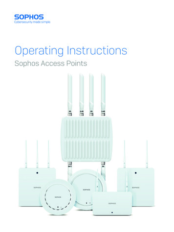
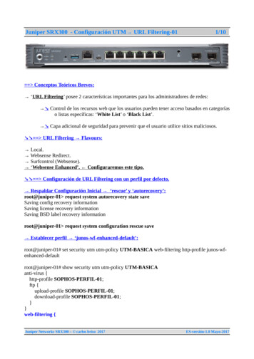
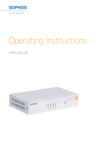
CE Labeling, FCC and ApprovalsThe UTM 110/120 appliance complies with FCC Class B, CE, C-Tick, VCCIand UL.Important Note: For computer systems to remain CE and FCC compliant,only CE and FCC compliant parts may be used. Maintaining CE and FCCcompliance also requires proper cable and cabling techniques.Operating Elements and ConnectionsSophos UTM 110/120 (rev.5)LED: dataactivity linkVGA power COMswitch2 x USBLED: dataactivity link4 x 10/100/1000Base-TX portsControlsPower (LED Display)GreenPower onGreen / YellowLinkGreen / YellowActivityYellowHard driveLEDs on each Ethernet connector (Speed LED: left, Act/Link LED: right)Act/LinkGreenConstantly1. The Ethernet port is receiving power.2. Good connection between the Ethernetport and hub.Off1. T he adapter and switch arenot receiving power.2. No connection between bothends of the network.3. Network drivers have not been loadedor do not function correctly.FlashingSpeedUTM 110/120 Operating InstructionsThe adapter is sending or receiving networkdata. The frequency of the flashes varies withthe amount of traffic.YellowOnOperating at 1000 MbpsGreenOnOperating at 100 MbpsOffOperating at 10 Mbps if Act/Link is on
6. Putting into OperationCaution: Risk of explosion if battery is replaced by an incorrect type. Disposeof used batteries according to the instructions.Scope of SupplyThe supplied parts are indicated in the Hardware Quick Start Guide.Mounting InstructionsThe hardware model UTM 110/120 can be placed on a stable horizontalsurface or can be mounted on the wall. Screws are not included in delivery.Use only screws that fit the mounting holes on the bottom side.To mount the appliance to the rack you need the optional Rack Mounting Kit,which you can purchase through certified Sophos partner near you.General PrecautionsReview the electrical and general safety precautions that came with thecomponents you are adding to your appliance.Rack PrecautionsÌÌ Ensure that the leveling jacks on the bottom of the rack are fully extendedto the floor with the full weight of the rack resting on them.ÌÌ In single rack installation, stabilizers should be attached to the rack.ÌÌ In multiple rack installations, the racks should be coupled together.ÌÌ A lways make sure the rack is stable before extending a component fromthe rack.ÌÌ Y ou should extend only one component at a time–extending two or moresimultaneously may cause the rack to become unstable.General Server PrecautionsÌÌ Review the electrical and general safety precautions that came with thecomponents you are adding to your appliance.ÌÌ I nstall the heaviest server components on the bottom of the rack first, andthen work up.ÌÌ A llow the hot plug hard drives and power supply modules to cool beforetouching them.ÌÌ A lways keep the rack‘s front door, all panels and server componentsclosed when not servicing to maintain proper cooling.UTM 110/120 Operating Instructions
UTM 110/120 Operating InstructionsRack Mounting ConsiderationsÌÌ Ambient operating temperature: If installed in a closed or multi-unit rackassembly, the ambient operating temperature of the rack environmentmay be greater than the ambient temperature of the room. Therefore,you should install the equipment in an environment compatible with themanufacturer’s maximum rated ambient temperature.ÌÌ R educed airflow: Equipment should be mounted into a rack with sufficientairflow to allow cooling.ÌÌ M echanical loading: Equipment should be mounted into a rack so that ahazardous condition does not arise due to uneven mechanical loading.ÌÌ C ircuit overloading: Consideration should be given to the connectionof the equipment to the power supply circuitry and the effect that anypossible overloading of circuits might have on overcurrent protection andpower supply wiring. Appropriate consideration of equipment nameplateratings should be used when addressing this concern.ÌÌ Reliable grounding: Reliable grounding must be maintained at all times.To ensure this, the rack itself should be grounded. Particular attentionshould be given to power supply connections other than the directconnections to the branch circuit (i.e., the use of power strips, etc.).Connection and ConfigurationHow to connect the appliance is described in the Hardware Quick StartGuide. For configuration you can follow the initial setup wizard described inthe WebAdmin Quick Start Guide or cancel it and perform a manual setup(see the Sophos UTM Administration Guide).Serial ConsoleYou can connect a serial console to the COM port of the Sophos UTMhardware appliances. You can use, for instance, the Hyperterminal terminalprogram included with most versions of Microsoft Windows to log on to theappliance console. You will need a RJ45 to DB9 adapter cable to connect theconsole to your hardware appliance.The required connection settings are:Bits per second: 38,400, Data bits: 8, Parity: N (none), Stop bits: 1. Access viathe serial console is activated by default on ttyS1. The connections of theappliances and the respective functionality are listed in chapter "OperatingElements and Connections."United Kingdom Sales:Tel: 44 (0)8447 671131Email: sales@sophos.comNorth American Sales:Toll Free: 1-866-866-2802Email: nasales@sophos.comBoston, USA Oxford, UK Copyright 2012. Sophos Ltd. All rights reserved.All trademarks are the property of their respective owners.Sophos Operating Instructions 02.12v1.dNAAustralia & New Zealand SalesTel: 61 2 9409 9100Email: sales@sophos.com.au
UTM 110/120 Operating Instructions 6. Putting into Operation Caution: Risk of explosion if battery is replaced by an incorrect type.