Transcription
Operating InstructionsSophos Access Points
Operating InstructionsForewordWe are pleased to welcome you as a new Sophos Access Point customer.These operating instructions will help you install and configure the accesspoint and provide technical specifications of all Sophos access point models.In addition, please also see the following documents that contain usefulinformation on safety, regulatory compliance, and configuration options:ÌÌ Sophos Access Points Safety Instructions and Regulatory InformationÌÌ Sophos UTM Administration Guide: Configuring theUTM hardware and software applianceThe instructions must be read carefully prior to using the device and shouldbe kept in a safe place. You may download all user manuals and additionaldocumentation from the Sophos Knowledgebase at aspx.IntroductionUTM Wireless Protection simplifies the operation of secure and reliable wirelessnetworks. It combines affordable and configuration-less access points througha built-in wireless controller in the in Sophos UTM. The wireless controller itselfcentrally manages all wireless access points; all you need to do is plug in thedevice anywhere in your network. The access point will find the controller, fetchits configuration and become operable within seconds. In addition, it easilyprovides wireless guest Internet access during the initial setup, unless youexplicitly deny automatic configuration.InstallationPreliminary stepsPlease update your UTM appliance to the latest version available. Note that youalso need a valid UTM Wireless Protection subscription to operate the SophosAccess Points.Connect the access point to the internal networkDecide where you would prefer to place the access point, and put the accesspoint in that location. For mounting instructions, see below. Now connect theaccess point to your internal network by plugging in the network cable to theaccess point’s RJ45 or LAN (PoE) Ethernet interface, respectively.Wireless Access Points1
Operating InstructionsConnect the access point to the power supplyThe AP 15, AP 15C, AP 55, AP 55C, AP 100, AP 100C, and AP 100X can bepowered directly through the Power-over-Ethernet-injector. Note that it is alsopossible to power them by a PoE-compliant switch. For more information onPoE-injectors, see below.Connect the AP 15 to the power supply. Please use the power supply from thescope of supply. Note that the AP 15 can also be operated through a PoE-injectoror PoE-compliant switch.Start the communication between the access point and the UTMapplianceWhen connected to the network, the access point will try to receive an IP addressvia DHCP. Therefore, you need either the UTM appliance (with a DHCP serverenabled and listening on the interface the access point is connected to) or anyother DHCP server to provide an IP address for the access point.After successfully receiving an IP address, the access point will communicatewith the UTM appliance. For this to happen, the UTM appliance needs to be putin the upstream of the access points, either being the default gateway of theaccess points (which was provided by the DHCP service) or on the default route(most likely your route to the Internet).Please note that the actual Internet access is not necessary to use UTM WirelessProtection. While waiting for DHCP and searching for the UTM appliance, theaccess point’s power LED will blink slowly.Enable UTM Wireless Protection on the UTM applianceIn WebAdmin, navigate to the Wireless Protection menu entry. On the GlobalSettings tab, click the Enable button. When enabling Wireless Protection for thefirst time, the Initial Setup frame will appear. It shows the configuration which willbe created: A separate Wireless “Guest” network using WPA2 personal with DHCPfor wireless clients, which will be allowed to use DNS on the UTM appliance andthe “Web Surfing” service.The pre-shared key is auto-generated and will only be shown in this section. Thisconfiguration is intended as a template, you can edit the settings at any timeon the Wireless Protection Wireless Networks tab. You can also skip the initialsetup by ticking the checkbox on the bottom of the section.Wireless Access Points2
Operating InstructionsAccepting the access pointThe UTM appliance will start to communicate with the access point and theywill show up as “Pending” on the Wireless Protection Access Points tab inWebAdmin. The ID of the Access Points, shown in square brackets, is also printedon the bottom of the device. It can be used to distinguish the access point. Byclicking the Accept button, you are given the option to select the channel thisaccess point will transmit on. When leaving the channel setting on “Auto”, theaccess point will use the least used channel.We also suggest to give the access point a meaningful location (e.g., “MeetingRoom”) as this will ease handling multiple access points. After clicking the Savebutton, the access points will reboot. Upon reconnect, the access point willcheck if a more recent firmware is available. If so, they will automatically performa firmware update. During the firmware update, the access point’s power LED willblink rapidly.Important note: Do not unplug the power while the firmware is updating.Otherwise the access point will be rendered inoperable and must be returned tothe reseller.The access point will then reboot to complete the firmware update. If no newfirmware is available, the access point is operational and appears as “Active” inWebAdmin.Country code selection usage (WLAN devices)Note: According to FCC regulations, all WLAN devices marketed and sold inthe U.S. must be restricted to U.S. channels only. Therefore, the country codeselection is applicable to non-U.S. models only. So changing the country settingof any Sophos AP sold in the U.S. will not modify authorized parameters suchas RF channels, which means that the Access Point will always operate in U.S.authorized channels.Resetting an access point (models APX320/530/740)For a normal reboot, press the hardware reset button for 3-5 seconds. Anyconfiguration will be retained.For a factory reset, press the hardware resest button for 15-20 seconds. Anyconfiguration will be removed and the access point needs to be newly registered.Wireless Access Points3
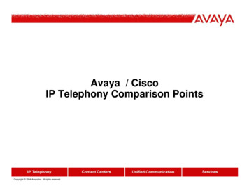
Operating InstructionsAP 15Scope of supplySophos AP 15Security Notes2 Detachabledipole antennaPower supply2 screwsand dowelsEthernetcableImportant note: Sophos AP 15 requires Sophos UTM V 9.207 to be installed.Mounting instructionsThe Sophos AP 15 can be mounted on the wall. Screws are included in delivery.ControlsLEDGreen - blinking slowlyAP is bootingGreen - blinking rapidlyNetwork connectivityOrange - blinking slowlyNo connection to the Sophos UTMOrange - blinking rapidlyFirmware updateInterfaces and buttons12V DC-INPowerLAN (PoE)10/100/1000 Base-TX interfaceTechnical specifications10/100/1000 Base-TXPowerSophos AP 15ChassisPlastic housing, whiteMaximum throughput300 Mbit/sLAN interfaces1 x 10/100/1000 Base-TXSupported WLAN standards802.11 b/g/n 2.4 GHzAntenna2 x detachable dipoleantenna (2 dBi)Connector type: RP-SMAFrequencies / channelsETSIFCC2.412–2.472 GHz (Channels 1-13) 2.412-2.462 GHz (channels 1-11)Wireless Access PointsPower supply12 Vdc / 1 APower consumption2.5 W (max.)Power-over-Ethernet802.3afDimensions W x H x D194 x 32 x 115 mmWeight260gTemperature rangeOperating: 0 C to 45 CHumidity (non-condensing)0% to 90%MountingDesktop / wallSupported security standardsWPA/WPA2, WEP, 802.1X (RADIUS)Number of supported SSIDs8Regulatory complianceCE, FCC, IC, CB, cULus, SRRCStorage: -20 C to 60 C4
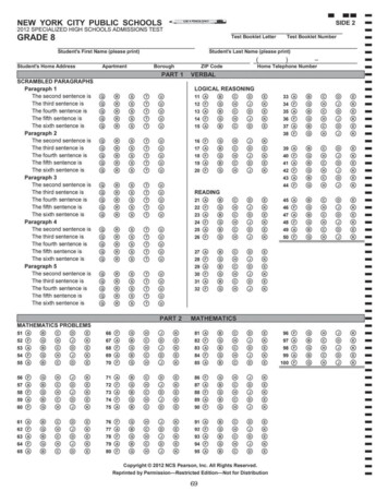
Operating InstructionsAP 15 Mounting template12 cm (4,72 in)Do not shrink to fit when printingWireless Access Points5
Operating InstructionsAP 15CScope of supplySophos AP 15CSecurity NotesMountingbracketScrews andT-rail clipsEthernetcableImportant note: Sophos AP 15C requires Sophos UTM V 9.400 to be installed.Mounting instructionsThe Sophos AP 15C can be mounted on the ceiling. Screws are included indelivery. Use the screws from the scope of supply or screws whose dimensionscorrespond with the mounting holes in the bracket.1. M ount the bracket on the ceiling.Use the screws and anchors from the scope of supply.2. Place the access point on the bracket.Place the housing on the bracket and lock it by turning clockwise until stop.ConsolePower10/100/1000 Base-TXControlsLEDGreen - blinking slowlyAP is bootingGreen - blinking rapidlyNetwork connectivityOrange - blinking slowlyNo connection to the Sophos UTMOrange - blinking rapidlyFirmware updateInterfaces and buttonsWireless Access Points12V DC-INPowerLAN (PoE)10/100/1000 Base-TX interface6
Operating InstructionsTechnical specificationsSophos AP 15CChassisPlastic, whitePhysical securityKensington lockMaximum theoreticalthroughput300 Mbps (5GHz / 802.11an) 300 Mbps (2.4GHz / 802.11n)LAN interfaces1 x 10/100/1000 Base-TXSupported WLAN standards802.11a/b/g/nAntenna4 x internal antennasFrequencies / channelsETSI2.412–2.472 GHz (Channels 1-13) 5.180-5.240GHz(channels 36-48)FCC2.412-2.462GHz (channels 1-11)U-NII-1:5.180-5.240GHz(channels 36-48)U-NII-3:5.745-5.825GHz(channels 149-165)MIC2.412-2.472GHz (channels 1-13)Wireless Access PointsW52:5.180-5.240GHz(channels 36-48)Power supply12 Vdc / 1 APower consumption7 W (max.)Power-over-Ethernet802.3afDimensions W x H x D176 x 29.86mmWeight265gTemperature rangeOperating: 0 C to 50 CHumidity (non-condensing)0% to 90%MountingCeilingSupported security standardsWPA/WPA2, WEP, 802.1X (RADIUS)Number of supported SSIDs8Regulatory complianceCB, CE, UL, FCC, IC, MIC, VCCI, RCM7
Operating InstructionsAP 55Scope of supplySophos AP 55Security Notes2 Detachabledipole antenna4 screws, dowelsand metal platesEthernetcableImportant note: Sophos AP 55 requires Sophos UTM V 9.308 to be installed.Mounting instructionsThe Sophos AP 55 can be mounted on the wall. A mounting kit is included indelivery.ControlsLEDGreen - blinking slowlyAP is bootingGreen - blinking rapidlyNetwork connectivityOrange - blinking slowlyNo connection to the Sophos UTMOrange - blinking rapidlyFirmware updateInterfaces and buttonsPowerUSB12V DC-INPowerLAN (PoE)10/100/1000 Base-TX interfaceConsoleConsole access for debugging purposesUSBCurrently not used; reserved for future useConsole10/100/1000 Base-TXWireless Access Points8
Operating InstructionsTechnical specificationsSophos AP 55ChassisPlastic housing, whitePhysical securityKensington lockMaximum theoreticalthroughput867 Mbps (5GHz / 802.11ac) 300 Mbps (2.4GHz / 802.11n)LAN interfaces1 x 10/100/1000 Base-TXSupported WLAN standards802.11a/b/g/n/acAntenna2 x detachable dipoleantenna (2 dBi)Frequencies / channelsETSIConnector type: RP-SMA2.412–2.472 GHz (Channels 1-13) RLAN sub-band 1:5.180-5.320GHz(channels 36-64)RLAN sub-band 2:5.500-5.580GHz(channels 100-116)5.660-5.700GHz(channels 132-140)FCC5.180-5.240GHz(channels 36-48)U-NII-1:5.180-5.240GHz(channels 36-48)U-NII-2:5.260-5.320GHz(channels 52-64)U-NII-2e:5.500-5.580GHz(channels 100-116)5.660-5.700GHz(channels 132-140)U-NII-3:5.745-5.825GHz(channels 149-165)Wireless Access PointsPower supply12 Vdc / 4 APower consumption17 W (max.)Power-over-Ethernet802.3atDimensions W x H x D183 x 36 x 183 mmWeight500gTemperature rangeOperating: 0 C to 50 CHumidity (non-condensing)0% to 90%MountingDesktop / wallSupported security standardsWPA/WPA2, WEP, 802.1X (RADIUS)Number of supported SSIDs8 per radio (16 in total)Regulatory complianceCE, FCC, IC, CB, cULus, MIC, VCCI9
Operating InstructionsAP 55CScope of supplySophos AP 55CSecurity NotesMountingbracketScrews andT-rail clipsEthernetcableImportant note: Sophos AP 55C requires Sophos UTM V 9.308 to be installed.Mounting instructionsThe Sophos AP 55C can be mounted on the ceiling. Screws are included indelivery. Use the screws from the scope of supply or screws whose dimensionscorrespond with the mounting holes in the bracket.1. M ount the bracket on the ceiling.Use the screws and anchors from the scope of supply.2. Place the access point on the bracket.Place the housing on the bracket and lock it by turning clockwise until stop.ControlsPower10/100/1000 Base-TXLEDGreen - blinking slowlyAP is bootingGreen - blinking rapidlyNetwork connectivityOrange - blinking slowlyNo connection to the Sophos UTMOrange - blinking rapidlyFirmware updateInterfaces and buttonsWireless Access Points12V DC-INPowerLAN (PoE)10/100/1000 Base-TX interface10
Operating InstructionsTechnical specificationsSophos AP 55CChassisTop enclosure: plastic, white; bottom enclosure: metal, whitePhysical securityKensington lockMaximum theoreticalthroughput867 Mbps (5GHz / 802.11ac) 300 Mbps (2.4GHz / 802.11n)LAN interfaces1 x 10/100/1000 Base-TXSupported WLAN standards802.11a/b/g/n/acAntenna4 x internal antennasFrequencies / channelsETSI2.412–2.472 GHz (Channels 1-13) RLAN sub-band 1:5.180-5.320GHz(channels 36-64)RLAN sub-band 2:5.500-5.580GHz(channels 100-116)5.660-5.700GHz(channels 132-140)FCC2.412-2.462GHz (channels 1-11)U-NII-1:5.180-5.240GHz(channels 36-48)U-NII-2:5.260-5.320GHz(channels 52-64)U-NII-2e:5.500-5.580GHz(channels 100-116)5.660-5.700GHz(channels 132-140)U-NII-3:5.745-5.825GHz(channels 149-165)Wireless Access PointsPower supply12 Vdc / 1.5 APower consumption20 W (max.)Power-over-Ethernet802.3atDimensions W x H x D200 x 37mmWeight630gTemperature rangeOperating: 0 C to 50 CHumidity (non-condensing)0% to 90%MountingCeilingSupported security standardsWPA/WPA2, WEP, 802.1X (RADIUS)Number of supported SSIDs8 per radio (16 in total)Regulatory complianceCE, FCC, IC, CB, cULus, SRRC, NCC, BSMI11
Operating InstructionsAP 100Scope of supplySophos AP 100Security Notes3 Detachabledipole antenna4 screws, dowelsand metal platesEthernetcableImportant note: Sophos AP 55 requires Sophos UTM V 9.308 to be installed.Mounting instructionsThe Sophos AP 55 can be mounted on the wall. A mounting kit is included indelivery.ControlsLEDGreen - blinking slowlyAP is bootingGreen - blinking rapidlyNetwork connectivityOrange - blinking slowlyNo connection to the Sophos UTMOrange - blinking rapidlyFirmware updateInterfaces and buttonsPowerUSB12V DC-INPowerLAN (PoE)10/100/1000 Base-TX interfaceConsoleConsole access for debugging purposesUSBCurrently not used; reserved for future useConsole10/100/1000 Base-TXWireless Access Points12
Operating InstructionsTechnical specificationsSophos AP 100ChassisPlastic housing, whitePhysical securityKensington lockMaximum theoreticalthroughput1.3 Gbps (5GHz / 802.11ac) 450 Mbps (2.4GHz / 802.11n)LAN interfaces1 x 10/100/1000 Base-TXSupported WLAN standards802.11a/b/g/n/acAntenna3 x detachable dipoleantenna (2 dBi)Frequencies / channelsETSIConnector type: RP-SMA2.412–2.472 GHz (Channels 1-13) RLAN sub-band 1:5.180-5.320GHz(channels 36-64)RLAN sub-band 2:5.500-5.580GHz(channels 100-116)5.660-5.700GHz(channels 132-140)FCC2.412-2.462GHz (channels 1-11)U-NII-1:5.180-5.240GHz(channels 36-48)U-NII-2:5.260-5.320GHz(channels 52-64)U-NII-2e:5.500-5.580GHz(channels 100-116)5.660-5.700GHz(channels 132-140)U-NII-3:5.745-5.825GHz(channels 149-165)Wireless Access PointsPower supply12 Vdc / 4 APower consumption17 W (max.)Power-over-Ethernet802.3atDimensions W x H x D183 x 36 x 183 mmWeight505gTemperature rangeOperating: 0 C to 50 CHumidity (non-condensing)0% to 90%MountingDesktop / wallSupported security standardsWPA/WPA2, WEP, 802.1X (RADIUS)Number of supported SSIDs8 per radio (16 in total)Regulatory complianceCE, FCC, IC, CB, cULus13
Operating InstructionsAP 100CScope of supplySophos AP 100CSecurity NotesMountingbracketScrews andT-rail clipsEthernetcableImportant note: Sophos AP 100C requires Sophos UTM V 9.308 to be installed.Mounting instructionsThe Sophos AP 100C can be mounted on the ceiling. Screws are included indelivery. Use the screws from the scope of supply or screws whose dimensionscorrespond with the mounting holes in the bracket.1. Mount the bracket on the ceiling.Use the screws and anchors from the scope of supply.2. Place the access point on the bracket.Place the housing on the bracket and lock it by turning clockwise until stop.ControlsPower10/100/1000 Base-TXLEDGreen - blinking slowlyAP is bootingGreen - blinking rapidlyNetwork connectivityOrange - blinking slowlyNo connection to the Sophos UTMOrange - blinking rapidlyFirmware updateInterfaces and buttonsWireless Access Points12V DC-INPowerLAN (PoE)10/100/1000 Base-TX interface14
Operating InstructionsTechnical specificationsSophos AP 100CChassisTop enclosure: plastic, white; bottom enclosure: metal, whitePhysical securityKensington lockMaximum theoreticalthroughput1.3 Gbps (5GHz / 802.11ac) 450 Mbps (2.4GHz / 802.11n)LAN interfaces1 x 10/100/1000 Base-TXSupported WLAN standards802.11a/b/g/n/acAntenna6 x internal antennasFrequencies / channelsETSI2.412–2.472 GHz (Channels 1-13) RLAN sub-band 15.180-5.320GHz(channels 36-64)RLAN sub-band 2:5.500-5.580GHz(channels 100-116)5.660-5.700GHz(channels 132-140)FCC2.412-2.462GHz (channels 1-11)U-NII-1:5.180-5.240GHz(channels 36-48)U-NII-2:5.260-5.320GHz(channels 52-64)U-NII-2e:5.500-5.580GHz(channels 100-116)5.660-5.700GHz(channels 132-140)U-NII-3:5.745-5.825GHz(channels 149-165)Wireless Access PointsPower supply12 Vdc / 1.5 APower consumption20 W (max.)Power-over-Ethernet802.3atDimensions W x H x D200 x 37mmWeight630gTemperature rangeOperating: 0 C to 50 CHumidity (non-condensing)0% to 90%MountingCeilingSupported security standardsWPA/WPA2, WEP, 802.1X (RADIUS)Number of supported SSIDs8 per radio (16 in total)Regulatory complianceCE, FCC, IC, CB, cULus, NCC, BSMI15
Operating InstructionsAP 100XScope of supplySophos AP 100XSecurity Notes6 Detachabledipole antenna4 wood screwsand wood/gyprockplug, 4 M6 screwsand washers2 metal straps1 wall mount plate1 M25cable glandGrounding wireEthernetcableImportant note: Sophos AP 100X requires Sophos UTM V 9.308 to be installed.Mounting instructionsThe Sophos AP 100X can be mounted on a pole. A mounting kit is included indelivery.Warning: The equipment has a separate protective earthing terminal on thechassis that must be permanently connected to earth ground to adequatelyground the chassis and protect the operator from electrical hazards.Caution: Before equipment installation begins, ensure that a service personnelhas attached an appropriate grounding lug to the grounding cable that you supply.Connect a ground cable from the outdoor unit to anappropriate grounding point.Power installation must be performed with qualified electrician and followed withNational Electrical Code, ANSI/NFPA 70 and Canadian Electrical Code, Part I, CSAC22.1.To connect earth ground to Unit:1. Connect one end of the grounding cable to a proper earth ground.10/100/1000 Base-TX2. Place the grounding lug attached to the groundingcable over the protective earthing terminal.3. Secure the grounding lug to the protective earthingterminal with the washers and screws.4. Dress the grounding cable and ensure that it does nottouch or block access to other components.Warning: At first before powered on, connect the frame of the unit to earth. Forearthing wire, green-and-yellow insulation is required and the cross-sectionalarea of the conductor must be more than 0.75mm2 or 18 AWG.Wireless Access Points16
Operating InstructionsControlsLEDPower (Green) - continuously onPower onWLAN (Green) - blinking rapidlyWLAN activityWLAN (Green) - blinking regularlyFirmware updateLAN (Green) - blinking rapidlyNetwork connectivityInterfaces and buttonsLAN (PoE)10/100/1000 Base-TX interfaceResetCurrently not supportedTechnical specificationsSophos AP 100XChassisMetal housing, whiteIP Code67Maximum throughput1.3 Gbps (5GHz / 802.11ac) 450 Mbps (2.4GHz / 802.11n)Number of radios2MIMO capabilities3x3:3LAN interfaces1 x 10/100/1000 Base-TXAntenna6 x external dipole antennaAntenna gain4 dBi @ 2.4GHz, 6 dBi @5GHzSupported WLAN standards802.11a/b/g/n/acFrequencies / channelsETSI2.412-2.472GHz (channels 1-13)Connector type:
point and provide technical specifications of all Sophos access point models. In addition, please also see the following documents that contain useful information on safety, regulatory compliance, and configuration options: Ì Sophos Access Points Safety Instructions and Regulatory Infor