Transcription
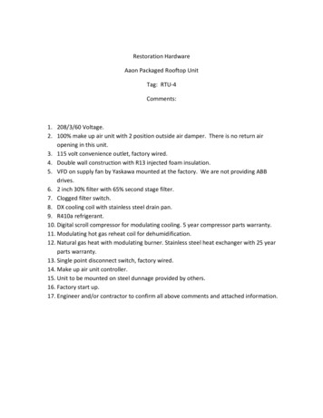
Restoration HardwareAaon Packaged Rooftop UnitTag: RTU-4Comments:1. 208/3/60 Voltage.2. 100% make up air unit with 2 position outside air damper. There is no return airopening in this unit.3. 115 volt convenience outlet, factory wired.4. Double wall construction with R13 injected foam insulation.5. VFD on supply fan by Yaskawa mounted at the factory. We are not providing ABBdrives.6. 2 inch 30% filter with 65% second stage filter.7. Clogged filter switch.8. DX cooling coil with stainless steel drain pan.9. R410a refrigerant.10. Digital scroll compressor for modulating cooling. 5 year compressor parts warranty.11. Modulating hot gas reheat coil for dehumidification.12. Natural gas heat with modulating burner. Stainless steel heat exchanger with 25 yearparts warranty.13. Single point disconnect switch, factory wired.14. Make up air unit controller.15. Unit to be mounted on steel dunnage provided by others.16. Factory start up.17. Engineer and/or contractor to confirm all above comments and attached information.
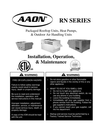
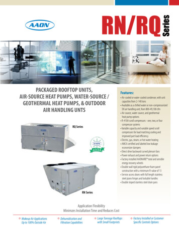
Guide Specifications - Aaon RN Series Rooftop UnitsPackaged Rooftop Units / Outdoor Air Handling UnitsPart 1 - General1.01 Related Documents1.02 General DescriptionA.This section includes the design, controls and installation requirements forpackaged rooftop units / outdoor air handling units.1.03 Quality AssuranceA.[RTU-4] Packaged air-cooled condenser units shall be certified in accordance withANSI/AHRI Standard 340/360 performance rating of commercial and industrialunitary air-conditioning and heat pump equipment.B.Unit shall be certified in accordance with UL Standard 1995/CSA C22.2 No. 236,Safety Standard for Heating and Cooling Equipment.C.[RTU-4] Unit and refrigeration system shall comply with ASHRAE 15, SafetyStandard for Mechanical Refrigeration.D.[RTU-4] Unit shall be certified in accordance with ANSI Z21.47b/CSA 2.3b andANSI Z83.8/CSA 2.6, Safety Standard Gas-Fired Furnaces.E.[RTU-4] Unit Energy Efficiency Ratio (EER) shall be equal to or greater thatprescribed by ASHRAE 90.1, Energy Efficient Design of New Buildings exceptLow-Rise Residential Buildings.F.[RTU-4] Unit shall be safety certified by ETL and ETL US listed. Unit nameplateshall include the ETL/ETL Canada label.1.04 SubmittalsA.Product Data: Literature shall be provided that indicates dimensions, operating andshipping weights, capacities, ratings, fan performance, filter information, factorysupplied accessories, electrical characteristics and connection requirements.Installation, Operation and Maintenance manual with startup requirements shall beprovided.B.Shop Drawings: Unit drawings shall be provided that indicate assembly, unitdimensions, construction details, clearances and connection details. Computergenerated fan curves for each fan shall be submitted with specific design operationpoint noted. Wiring diagram shall be provided with details for both power andcontrol systems and differentiate between factory installed and field installedwiring.1.05 Delivery, Storage, and Handling
A.Unit shall be shipped with doors screwed shut and outside air hood closed toprevent damage during transport and thereafter while in storage awaitinginstallation.B.Follow Installation, Operation and Maintenance manual instructions for rigging,moving, and unloading the unit at its final location.C.Unit shall be stored in a clean, dry place protected from construction traffic inaccordance with the Installation, Operation and Maintenance manual.1.06 WarrantyA.Manufacturer shall provide a limited “parts only” warranty for a period of 12months from the date of equipment startup or 18 months from the date of originalequipment shipment from the factory, whichever is less. Warranty shall covermaterial and workmanship that prove defective, within the specified warrantyperiod, provided manufacturer’s written instructions for installation, operation andmaintenance have been followed. Warranty excludes parts associated with routinemaintenance, such as belts and filters.Part 2 - Products2.01 ManufacturerA.Products shall be provided by the following manufacturers:1.AAON2.Substitute equipment may be considered for approval that includes at aminimum:a.[RTU-4] R-410A refrigerantb.[RTU-4] variable capacity compressors with 10-100% capacity.c.Direct drive supply fansd.Double wall cabinet constructione.Insulation with a minimum R-value of 13f.[RTU-4] Stainless steel drain pansg.Hinged access doors with lockable handlesh.All other provisions of the specifications must be satisfactorily addressed2.02 Rooftop UnitsA.General Description1.[RTU-4] Packaged rooftop unit shall include compressors, evaporator coils,
filters, supply fans, dampers, air-cooled condenser coils, condenser fans, reheatcoil, gas heaters, and unit controls.2.Unit shall be factory assembled and tested including leak testing of the DXcoils, pressure testing of the refrigeration circuit, and run testing of thecompleted unit. Run test report shall be supplied with the unit in the servicecompartment’s literature pocket.3.Unit shall have decals and tags to indicate lifting and rigging, service areas andcaution areas for safety and to assist service personnel.4.Unit components shall be labeled, including refrigeration system componentsand electrical and controls components.5.Estimated sound power levels (dB) shall be shown on the unit ratings sheet.6.Installation, Operation and Maintenance manual shall be supplied within theunit.7.Laminated color-coded wiring diagram shall match factory installed wiring andshall be affixed to the interior of the control compartment’s hinged access door.8.Unit nameplate shall be provided in two locations on the unit, affixed to theexterior of the unit and affixed to the interior of the control compartment’shinged access door.B.Construction1.All cabinet walls, access doors, and roof shall be fabricated of double wall,impact resistant, rigid polyurethane foam panels.2.Unit insulation shall have a minimum thermal resistance R-value of 13. Foaminsulation shall have a minimum density of 2 pounds/cubic foot and shall betested in accordance with ASTM D-1929 for a minimum flash ignitiontemperature of 610 F.3.Unit construction shall be double wall with G90 galvanized steel on both sidesand a thermal break. Double wall construction with a thermal break preventsmoisture accumulation on the insulation, provides a cleanable interior, preventsheat transfer through the panel, and prevents exterior condensation on the panel.4.Unit shall be designed to reduce air leakage and infiltration through the cabinet.Cabinet leakage shall not exceed 1% of total airflow when tested at 3 times theminimum external static pressure provided in AHRI Standard 340/360. Paneldeflection shall not exceed L/240 ratio at 125% of design static pressure, at amaximum 8 inches of positive or negative static pressure, to reduce air leakage.Deflection shall be measured at the midpoint of the panel height and width.Continuous sealing shall be included between panels and between access doorsand openings to reduce air leakage. Piping and electrical conduit through cabinetpanels shall include sealing to reduce air leakage.
5.Roof of the air tunnel shall be sloped to provide complete drainage. Cabinetshall have rain break overhangs above access doors.6.[RTU-4] Access to filters, dampers, cooling coils, reheat coil, heaters,compressors, and electrical and controls components shall be through hingedaccess doors with quarter turn, zinc cast, lockable handles. Full length stainlesssteel piano hinges shall be included on the doors.7.Exterior paint finish shall be capable of withstanding at least 2,500 hours, withno visible corrosive effects, when tested in a salt spray and fog atmosphere inaccordance with ASTM B 117-95 test procedure.8.Units with cooling coils shall include double sloped 304 stainless steel drainpans.9.Unit shall be provided with base discharge and return air openings. All openingsthrough the base pan of the unit shall have upturned flanges of at least 1/2 inchin height around the opening.10. Unit shall include lifting lugs on the top of the unit.11. [RTU-4] Unit base shall be fabricated of 1 inch thick double wall, impactresistant, rigid polyurethane foam panels.C.Electrical1.[RTU-4] Unit shall be provided with factory installed and factory wired, nonfused disconnect switch.2.[RTU-4] Unit shall be provided with a factory installed and field wired 115V, 20amp GFI outlet in the unit control panel.D.Supply Fans1.Unit shall include direct drive, unhoused, backward curved, plenum supply fans.2.Blowers and motors shall be dynamically balance and mounted on rubberisolators.3.[RTU-4] Motors shall be premium efficiency ODP with ball bearings rated for200,000 hours service with external lubrication points.4.[RTU-4] Variable frequency drives shall be factory wired and mounted in theunit. Fan motors shall be premium efficiency.E.[RTU-4] Cooling Coils1.[RTU-4] Evaporator Coilsa.[RTU-4] Coils shall be designed for use with R-410A refrigerant andconstructed of copper tubes with aluminum fins mechanically bonded to the
tubes and galvanized steel end casings. Fin design shall be sine wave rippled.F.b.[RTU-4] Coils shall have interlaced circuitry and shall be standard capacity.c.Coils shall be helium leak tested.d.Coils shall be furnished with factory installed thermostatic expansion valves.[RTU-4] Refrigeration System1.[RTU-4] Unit shall be factory charged with R-410A refrigerant.2.[RTU-4] Compressors shall be scroll type with thermal overload protection,independently circuited and carry a 5 year non-prorated warranty, from the dateof original equipment shipment form the factory.3.Compressors shall be mounted in an isolated service compartment which can beaccessed without affecting unit operation. Lockable hinged compressor accessdoors shall be fabricated of double wall, rigid polyurethane foam injected panelsto prevent the transmission of noise outside the cabinet.4.Compressors shall be isolated from the base pan with the compressormanufacturer’s recommended rubber vibration isolators, to reduce anytransmission of noise from the compressors into the building area.5.Each refrigeration circuit shall be equipped with thermostatic expansion valvetype refrigerant flow control.6.Each refrigeration circuit shall be equipped with automatic reset low pressureand manual reset high pressure refrigerant safety controls, Schrader type servicefittings on both the high pressure and low pressure sides and a factory installedreplaceable core liquid line filter driers.7.[RTU-4] Unit shall include a variable capacity scroll compressor on the leadrefrigeration circuits which shall be capable of modulation from 10-100% of itscapacity.8.[RTU-4] Lead refrigeration circuits shall be provided with hot gas reheat coil,modulating valves, electronic controller, supply air temperature sensor and acontrol signal terminal which allow the unit to have a dehumidification mode ofoperation, which includes supply air temperature control to prevent supply airtemperature swings and overcooling of the space.9.[RTU-4] Lag refrigeration circuits shall be provided with factory installed hotgas bypass to protect against evaporator frosting and to prevent excessivecompressor cycling.G.[RTU-4] Condensers1.[RTU-4] Air-Cooled Condenser
H.a.Condenser fans shall be a vertical discharge, axial flow, direct drive fans.b.Coils shall be designed for use with R-410A refrigerant and constructed ofcopper tubes with aluminum fins mechanically bonded to the tubes andaluminum end casings. Fin design shall be sine wave rippled.c.Coils shall be designed for a minimum of 10 F of refrigerant sub-cooling.d.Coils shall be helium leak tested.[RTU-4] Gas Heating1.[RTU-4] Stainless steel heat exchanger furnace shall carry a 25 year nonprorated warranty, from the date of original equipment shipment from thefactory.2.[RTU-4] Gas furnace shall consist of stainless steel heat exchangers withmultiple concavities, an induced draft blower and an electronic pressure switchto lockout the gas valve until the combustion chamber is purged and combustionairflow is established.3.Furnace shall include a gas ignition system consisting of an electronic igniter toa pilot system, which will be continuous when the heater is operating, but willshut off the pilot when heating is not required.4.Unit shall include a single gas connection and have gas supply piping entrancesin the unit base for through-the-curb gas piping and in the outside cabinet wallfor across the roof gas piping.5.[RTU-4] Natural gas furnace shall be equipped with modulating gas valves,adjustable speed combustion blowers, stainless steel tubular heat exchangers,and electronic controller. Combustion blowers and gas valves shall be capableof modulation. Electronic controller includes a factory wired, field installedsupply air temperature sensor. Sensor shall be field installed in the supply airductwork. Supply air temperature setpoint shall be adjustable on the electroniccontroller within the controls compartment. 90 Mbtu/h, 150 MBtu/h, 195MBtu/h, 210 MBtu/h, 270 MBtu/h, 292.5 MBtu/h, 390 MBtu/h, and 540 MBtu/hgas heating assemblies shall be capable of operating at any firing rate between100% and 30% of their rated capacity. 405 MBtu/h and 810 MBtu/h gas heatingassemblies shall be capable of operating at any firing rate between 100% and20% of their rated capacity. 1080 MBtu/h gas heating assembly shall be capableof operating at any firing rate between 100% and 15% of its rated capacity.I.Filters1.[RTU-4] Unit shall include 4 inch thick, pleated panel filters with an ASHRAEefficiency of 65% and a MERV rating of 11, upstream of the cooling coil. Unitshall also include 2 inch thick, pleated panel pre filters with an ASHRAEefficiency of 30% and MERV rating of 8, upstream of the 4 inch standard filters.
2.J.[RTU-4] Unit shall include a clogged filter switch.Outside Air/Economizer1.K.[RTU-4] Unit shall include 100% motor operated outside air damper assemblyconstructed of extruded aluminum, hollow core, airfoil blades with rubber edgeseals and aluminum end seals. Damper blades shall be gear driven and designedto have no more than 15 CFM of leakage per sq. ft. of damper area whensubjected to 2 inches w.g. air pressure differential across the damper. Damperassembly shall be controlled by spring return, 2 position actuator. Unit shallinclude outside air opening bird screen and outside air hood with rain lip.Controls1.[RTU-4] Factory Installed and Factory Provided Controllera.Unit controller shall be capable of controlling all features and options of theunit. Controller shall be factory installed in the unit controls compartment andfactory tested. Controller shall be capable of stand alone operation with unitconfiguration, setpoint adjustment, sensor status viewing, unit alarm viewing,and occupancy scheduling available without dependence on a buildingmanagement system.b.Controller shall have an onboard clock and calendar functions that allow foroccupancy scheduling.c.Controller shall include non-volatile memory to retain all programmed valueswithout the use of a battery, in the event of a power failure.d.[RTU-4] Make Up Air Controllere.1.[RTU-4] Unit shall modulate cooling with constant airflow to meetventilation outside air loads. Cooling capacity shall modulate based onsupply air temperature.2.[RTU-4] With modulating hot gas reheat, unit shall modulate cooling andhot gas reheat as efficiently as possible, to meet outside air humidity loadsand prevent supply air temperature swings and overcooling of the space.3.[RTU-4] Unit shall modulate heating with constant airflow to meetventilation outside air loads. Heating capacity shall modulate based onsupply air temperature.[RTU-4] Unit configuration, setpoint adjustment, sensor status viewing, unitalarm viewing, and occupancy scheduling shall be accomplished withconnection to interface module with LCD screen and input keypad, interfacemodule with touch screen, or with connection to PC with free configurationsoftware. Controller shall be capable of connection with other factoryinstalled and factory provided unit controllers with individual unitconfiguration, setpoint adjustment, sensor status viewing, and occupancy
scheduling available from a single unit. Connection between unit controllersshall be with a modular cable. Controller shall be capable of communicatingand integrating with a LonWorks or BACnet network. [WattMaster OrionControls System]Part 3 - Execution3.01 Installation, Operation and MaintenanceA.Installation, Operation and Maintenance manual shall be supplied with the unit.B.Installing contractor shall install unit, including field installed components, inaccordance with Installation, Operation and Maintenance manual instructions.C.Start up and maintenance requirements shall be complied with to ensure safe andcorrect operation of the unit.
Unit B5C2341A1B1C1D2425 South Yukon Ave - Tulsa, Oklahoma 74107-2728 - Ph. (918) 583-2266 Fax (918) 583-6094AAONEcat32 Ver. 4.185 (SN: AFA-0H0D00F-00-0000000ABTag: RTU-4Job InformationJob Name:Job Number:Site Altitude:RefrigerantStatic PressureExternal:Evaporator:Filters Clean:Dirt AllowanceCooling SectionTotal Capacity:Sensible Capacity:Latent Capacity:Mixed Air Temp:Entering Air Temp:Lv Air Temp (Coil):Lv Air Temp (Unit)Digital Comp. Capacity Ratio:Supply Air Fan:SA Fan RPM / Width:Evaporator Coil:Evaporator Face Velocity:Unit InformationRestoration Hardware1204-00240 ftR-410A1.50 in. wg.0.20 in. wg.0.18 in. wg.0.35 in. wg.GrossNet672.41654.73 MBH408.98391.30 MBH263.43 MBH91.00 ºF DB74.00 ºF WB91.00 ºF DB74.00 ºF WB53.56 ºF DB53.36 ºF WB55.10 ºF DB54.00 ºF WB100%1 x 300D @ 6.27 BHP1077 / 6.742"43.8 ft² / 4 Rows / 14 FPI240.0 fpm615.010.312.1Application EER @ Op. Conditions:10.8Electrical DataRating:Unit FLA:Compressor 1:Compressor 2:Condenser Fans:Supply Fan:Combustion:208/3/60262Qty22613Cabinet Sound Power Levels*Octave Bands:Discharge LW(dB):Return 090749273*Sound power levels are given for informational purposes only. The sound levels are not guaranteed.Date Created/Modified: 6/11/2012 2:52:18 PM Using Ver 4.185 (OSN# 5770512)6015 / 6015 lbs.10500 / 1.5 in. wg.218.75 fpm / 24218.75 fpm / 241050092 ºF DB / 74 ºF WBEconomizer:Heating:Cabinet:Re-Heat Coil:Total:0.00 in. wg.0.09 in. wg.0.19 in. wg.0.03 in. wg.2.54 in. wg.PreHeat Type:Heating Type:Heating CFM:Total Capacity:OA Temp:RA Temp:Entering Air Temp:Leaving Air Temp:Input:Heater Qty:Consumption:Std (No Preheat)Nat. Gas Heat10500648.0 MBH6.0 DB / 4.0ºF WB72.0 ºF DB / 54.0 ºF WB6.0 ºF DB / 4.0 ºF WB63.2 ºF DB / 41.2 ºF WB810.0 MBH1810.0 MBHCapacity:LA DB / WB:RH:186 MBH70.00 ºF / 59.77 ºF55%Minimum Circuit Amp:Maximum Overcurrent:275300Heating SectionRe-Heat Coil:Rating InformationCooling Capacity (MBH):Cooling EER:Cooling IEER:Rated in accordance with AHRI 340/360Approx. Op./Ship Weights:Supply CFM/ESP:Pre-Filter FV / Qty:Final-Filter FV / Qty:Outside CFM:Ambient Date Printed: 6/13/2012 2:59:20 PM
30.0" STAR Plenum2425 South Yukon Ave - Tulsa, Oklahoma 74107-2728 - Ph. (918) 583-2266 Fax (918) 583-6094AAONEcat32 Ver. 4.185 (SN: 5770512-6GT7PAWS)JOB INFORMATION:Job Name:Job Tag:Rep Firm:Date:WHEEL SPECIFICATION:Restoration HardwareRTU-406/13/2012OPERATING CONDITIONS:Air Flow:Static Pressure:Relief Dampers DP:TSP:Site Altitude:TSP @ Sea Level:1,60030.0 in. x 1105008,459 FPM35 WR²Rated HP / Bypass:Frame Size:Nominal RPM:VAC/PH/HZ:EfficiencyEnclosure Type:Max Inertial Load:7.5 / No254T1170208/3/60Premium / 0.902ODP290 WR²MOTOR SELECTION:10,500 CFM2.54 in. Wg.0.00 in. Wg.FAN PERFORMANCE:Max RPM:Diameter x Qty:CFM:Tip Speed:Inertia:2.54 in. Wg.0.00 Ft2.54 in. Wg.FAN SOUND POWER (Inlet/Outlet):RPM:1077Octave Band:(Re 10 -12 watts)BHP:6
Guide Specifications - Aaon RN Series Rooftop Units Packaged Rooftop Units / Outdoor Air Handling Units Part 1 - General 1.01 Related Documents 1.02 General Description A. This section includes the design, controls and installation requirements for packaged rooftop units / outdoor air handling units. 1.03 Quality AssuranceFile Size: 492KB