Transcription
Tranquility Digital (DXM2)Troubleshooting GuideResidential PackagedDIGITAL GeothermalHeat Pumps97B0601N01Rev.: 4/3/14Table of ContentsIntroductionTroubleshooting Flow ChartFlow Chart Reference Symbols and DiagramsContactor ChartVerifying Pump Feedback SignalRemoving Powerhead on Modulating ValveChecking CompressorsReversing Valve Touch Test ChartPerformance TroubleshootingFunctional TroubleshootingCommissioning Worksheet:Typical Water Source Refrigeration Circuit(Heating Cycle)Basic Refrigeration SummaryRefrigeration TroubleshootingAuxiliary Heat CheckChecking Pump OutputCompressor Contactor Voltage CheckCheck CCH for 24 VoltsVerifying ContactorVerifying CapacitorChecking Pump Power CordReplacing Variable-Speed Pump Power HeadVerifying Power at Molded Plugfor CompressorVerifying AntifreezeSecond Stage 42526-272828292929303031313233Verifying 24V at Reversing ValveChecking Reversing Valve at DXM2A0-2 JumperChecking for Power at DXM2Verifying DC Voltage on DXM2 Boardfor Modulating Valve CheckTXV Bulb TestVerifying Dipswitch PositionReplacing High Pressure Water SwitchVerifying a ThermistorTurning Breaker on in Panelor Aux Heat ControlStatic Pressure CheckLocating Tstat Version and DXM2 VersionUltraCheck EZ Motor Diagnostic ToolChecking Dipswitches on DXM2Magnet Test to Shift Reversing ValveChecking Blower Line VoltageModulating Valve Loses ConfigurationHard Reset of ThermostatUnits Having LT1 Lockouts In HeatingDefinitions of ConditionsDXM2 Board Layout and DipswitchesDXM2 ControlsWiring DiagramsATC Thermostat Screens and Set UpRevision -484950-5354-5556-6264
Tr o u b l e s h o o t i n g G u i d e - Tranquility D i g i t a l ( D X M 2 ) P a c k a g e d U n i t sR e v. : 4 A p r i l , 2 0 1 4IntroductionTroubleshooting ClimateMaster Tranquility Digital Packaged Heat Pumps is quite straightforward.Most problems relate to water flow. Either there isn’t enough water flow or the entering water temperature is improperlysupplied. Most service problems can be addressed without refrigerant gauges. In fact, installing gauges on packaged heatpumps can do more harm than good because packaged heat pumps contain less refrigerant compared to split systems.The first thing to do is always perform a water side check (Heat of Extraction for Heating or Heat of Rejection for Cooling) todetermine if the unit is operating properly.Set up and diagnostics are made easier using the communicating thermostat (ATC32) or the communicating service tool(ACDU01). You must have ATC32 or ACDU01 to properly work on ClimateMaster Tranquility Digital units that use the DXM2control board.Follow the flow chart on the following pages to help diagnose and solve your issue.2Geothermal Heat Pump Systems
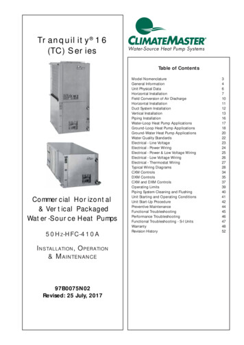
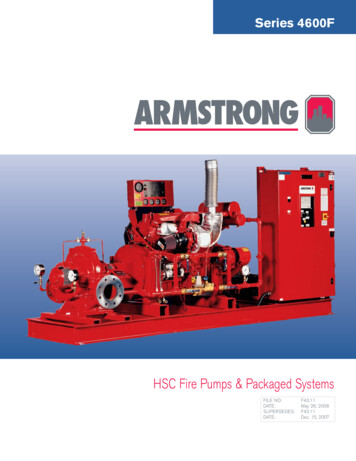
Tr o u b l e s h o o t i n g G u i d e - Tranquility D i g i t a l ( D X M 2 ) P a c k a g e d U n i t sR e v. : 4 A p r i l , 2 0 1 4Troubleshooting Flow ChartDid unitstart?Check that unitvoltage reads:197-254VNoYesDoes thermostat say Yes‘No Communication’?Is there powerto DXM2 24V?(18-31.5V)Establish powerA-ZIf it is still notcommunicating,check thethermostat wire(Be sure it is notrunning parallelalong powerwire). Ensure allwiring is landedproperly onboth DXM2 andthermostat.Disconnect andreconnect thewires from theDXM2. Thiswill reset thethermostat.Also ensure thereare no wire nuts;solder wires ifthey need to beextended.Verify thatDipswitch 1on S3is in ‘On’positionA-WHardreset thethermostatB-KIs the unitproperlyconfigured?See Section3.0 on page56.B-GHook Service Tool up toboard. Does Service Toolcommunicate with board?The unit didstart but itlocked outYesVerify thatthe DXM2’sdipswitchesare setproperly.Check Fault Codefrom thermostator service toolNoFaultNoReplace board ifcurrent board stilldoes not functionCheck that thecompressor is not in athermal overloadNoNoSee Fault Codesand PossibleCausesA-FCheck that thereare 24 volts at CC on YesDXM2 board and a callfor heating or coolingA-KNoReplace theDXM2 BoardCheck for 24V atcontactor18-31.5 voltsA-MYesA-ANoCheck and possiblyreplace wiringNext Page3
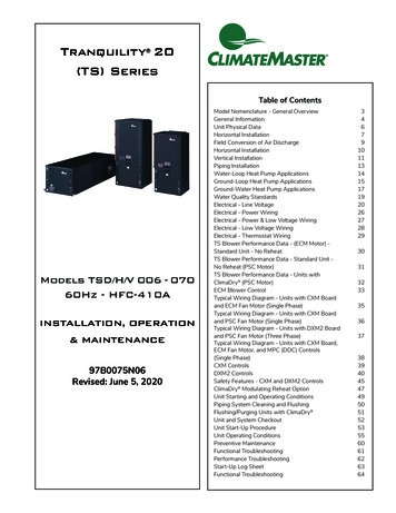
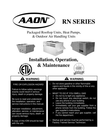
Tr o u b l e s h o o t i n g G u i d e - Tranquility D i g i t a l ( D X M 2 ) P a c k a g e d U n i t sR e v. : 4 A p r i l , 2 0 1 4Troubleshooting Flow ChartContinuedReplaceDXM2 boardNoCheck that theThe unit starts Yes Is there voltage YesA0-2 jumper on Yesbut the pumpto the pump?DXM2 board is indoes not(197-254V)PWM positionA-OA-VCheck DC Voltageat DXM2 BoardNoA0-2-Ground .5-10 VDCIs voltage in this range?YesYesVerify how the units areconfigured in the thermostat(refer to ‘Section 3.3 - UnitConfiguration’ on page 53).Be sure unit is configured for‘Variable Speed Pump Single’if unit is on it’s own loop. If unitshares a loop with other units,then ensure that the unit isconfigured for ‘Variable SpeedPump Parallel.’NoDoes the lowvoltage wiringhave a brokenwire?Check DC Voltageat DXM2 BoardReplacewire harnessT1-Ground 3-4 VDC(Pump off)0-2 VDC(Pump on)Is voltage in this range?A-JNoReplace pumppower headA-PMy unit hasa ModulatingValve. Is valveopening?Is the valve havingtrouble shuttingcompletely and/oris the unitlocking out?NoYesValve opens orcloses correctlyVerifyValve andpowerheadalignmentCheckYesVerify A0-2jumper is in10V position.A-VWhat are the T set points?Control defaults are 7 heating and 10 cooling.Open loop units with EWTless than 50 will needto lower T to 4-5 in theheating mode.B-LBe sure unitis configuredfor ModulatingValve.See Section 3.2on page 56.Third notch aimed down inunit position.Then reattach powerhead.A-CNext Page4Manually open the valve100%. Remove powerheadfrom valve with powerheadstill energized. Then verify thatthe notches on valve body arein the correct position.Geothermal Heat Pump Systems
Tr o u b l e s h o o t i n g G u i d e - Tranquility D i g i t a l ( D X M 2 ) P a c k a g e d U n i t sR e v. : 4 A p r i l , 2 0 1 4Troubleshooting Flow ChartContinuedVerify thatthe wiring onthe valve andDXM2 Boardare correct.See wiringdiagrams onpages 53-54.Verify that the DC voltage on DXM2between A0-2 and GND. Voltage shouldbe between 3.3-10VDC. This is the outputfrom the board to the valve.A-XThe unit usesa modulatingvalve but thethermostatcontinuesto show avariablespeed pump.Connect a piece of thermostat wirebetween T1 and GND on DXM2 so theDXM2 board sees no feedback.B-JValve doesfunction butwhen the unitshuts off, thevalve remainsopen.Does blowerturn on?Verify 3/4” Valve Dipswitchor 1” Valve DialA-CNoYesVerify inconfigurationthat the unitis configuredcorrectly for ECMIs 197-254V at theblower motor?B-INoCheck the wireharness andreplace if neededYesCheck continuity oncommunicating harnessfrom DXM2 to Module.Is there a broken wire?YesReplace wireharnessNoDoes the motortry to spinwhen giving a‘G’ call?NoReplacedefective partNext PageUse Emerson EZTool to troubleshootmotor and verifymotor or moduleB-F5
Tr o u b l e s h o o t i n g G u i d e - Tranquility D i g i t a l ( D X M 2 ) P a c k a g e d U n i t sR e v. : 4 A p r i l , 2 0 1 4Troubleshooting Flow ChartContinuedIs theblower loud?YesCheck yourmodel’s airflowconfiguration.See Section 3.1on page 56.Verify thatall grillesand registersare open.Check staticpressureB-DNoThere areno faults,but does thecompressorstart?NoYesVerify comp contactor.A-AVerify capacitor. Turn offpower and allow 5 minutesfor discharge. Then verifywith volt meter the UFreading compare to UFreading on capacitor. Iscapacitor good?A-NYesNoUnit starts but Yesdoes not shiftto coolingNoNoCall forcoolingYesA-QA-DCheckreversing valveconnection atDXM2. Do youhave 24 VAC?YesVerify24V atreversingvalveReplace compressorYesA-UNoNoVerify thatDipswitch 1:4is onReplacesolenoid onreversing valveYesA-TReplacedefectivewiringIf Dipswitch 1:4is on, replaceboardIn order to increase pressureand move a reversing valvethat is sticking, place unitin heating mode and thenremove blower door. Just afterremoving door, energize thevalve. If it still doesn’t shift, trya strong magnet to pull overinternal slide while energizing.B-HVerify RVoperationReplace the reversing valve ifit still does not shiftNext Page6Turn power off andremove molded plug oncompressor. Measureresistance between C-Sand C-R.YesReplace moldedplug and wireharnessReplace capacitor.Verify thatyou havecoolingcall atthermostatVerify voltage tocompressor atmolded plugGeothermal Heat Pump SystemsA-E
Tr o u b l e s h o o t i n g G u i d e - Tranquility D i g i t a l ( D X M 2 ) P a c k a g e d U n i t sR e v. : 4 A p r i l , 2 0 1 4Troubleshooting Flow ChartContinuedUnit doesnot seem tobe in secondstage. This isindicated by theperformancecheck beingabout 30%(low).YesVerify thatyou havesecondstage callNoVerify whetherthe thermostatis configuredfor multi-stageoperationNoYesDoesDXM2CCH have24V?A-LDoes the rectifierplug on the sideof the compressorhave 15-27 VDC?YesNoNoReplace therectifier plugYesVerify thatDipswitch1:4 is onIf Dipswitch 1:4is on, replaceboardWith unit running in secondstage, check amp drawof comp. Next, removerectifier plug. Amps shouldbe lower after removingplug. Reattach plug andverify that amps return toprevious higher reading.A-SNoReplacecompressorThe unit startedbut runs andloop tempcontinue to dropin the heatingmodeNoYesVerify the antifreezelevel where applicable.Remember that EWTbelow 45 needs 15 freeze protection.Verify with appropriatehydrometer.A-RYesAntifreeze hasbeen verifiedas having15 freezeprotection.Then cut theJW3 jumperYesIs there enough loop inthe ground? Is the loopmaking good contact?(Example: Is yourvertical loop groutedfrom top to bottom?)YesIs the loop turbulent?Min 2500 ReynoldsNumber.Use Pressure DropSoftware to verifyNext Page7
Tr o u b l e s h o o t i n g G u i d e - Tranquility D i g i t a l ( D X M 2 ) P a c k a g e d U n i t sR e v. : 4 A p r i l , 2 0 1 4Troubleshooting Flow ChartContinuedThe unitperiodicallylocks out on LT1in heating orhigh pressure incoolingYesIs there morethan one unitsharing acommon loop?Does this unithave a VariableSpeed Pump andis it configured forparallel pumping?YesNoATC ThermostatYessays ‘ECMConfigurationError’Properly configureunit. See Section 3.3and Section 3.4 onpage 57.Is the thermostatconfigured for the propermodel of the unit?(Example: TZ036) This isfound on thermostat’s unitconfiguration menu.YesDoes the unit have thecorrect ECM Motor? Checkthe ECM table, which is inthe unit’s IOM.Compare tothe motor in the unit.NoNoConfigureThe unit doesrun but ATCThermostatsays ‘ServiceNeeded’YesThis is the UnitPerformance Sentinel. Incooling mode if LT2 is 40 or lower or LT1 is 125 orgreater. In heating mode ifLT2 is 125 or greater.Go to FaultsCode 8.A-FNoNext Page8Verify pump issupplying enough flowusing Pressure DropSoftware. Closed loop2.25 - 3.0 gpm per ton.NoSee LockoutFaults on page51 under ‘FaultCodes’NoYesGeothermal Heat Pump SystemsNoReplace withcorrect motor
Tr o u b l e s h o o t i n g G u i d e - Tranquility D i g i t a l ( D X M 2 ) P a c k a g e d U n i t sR e v. : 4 A p r i l , 2 0 1 4Troubleshooting Flow ChartContinuedUnit runs butdoes not satisfyVerify the Water SidePerformanceYesHE HR NoYesHeat Extraction inBTUs (Heating)Heat Rejection inBTUs (Cooling)The unit is running.However, there isa load issue. Thehome is losing orgaining more thanthe capacity of theheat pump.Calculate using the formulafound on A-G.Check with performancedata. Is unit within 10%?A-GYesVerify load using amanual J program.You may also need toperform a blower doortest for true infiltrationand thermal imagingfor locating heat loss.Also consider a ductblast to verify thatair is being deliveredproperly.NoIf water flow and airflow are good,then verify refrigerant charge.Calculate superheat and subcooling.A-HThen check for proper TXV operationbefore adding or removing charge.Adjust charge if needed to propersuperheat and subcooling ranges.A-YThe unit runsbut auxiliaryheat is notworkingYesIs the thermostatcalling forauxiliary heat oremergency heat?YesDoes unit have197-254V atauxiliary heatstrip?NoVerify thatconfiguration is setto auxiliary heat inthermostat. Seesection 2.2.2 onpage 55.YesDoes DXM2have 24 VDCat EH1 and/orEH2?A-INoTurn breakeron in panel orin auxiliary heatcontrolYesNoReplaceDXM2B-CReplace heatstrap boardYesDoes the heatstrip controlboard have thesame 24 VDC asthe DXM2?NoReplacewire harness9
Tr o u b l e s h o o t i n g G u i d e - Tranquility D i g i t a l ( D X M 2 ) P a c k a g e d U n i t sR e v. : 4 A p r i l , 2 0 1 4Reference Symbols and Diagramsfor Flow Chart10Geothermal Heat Pump Systems
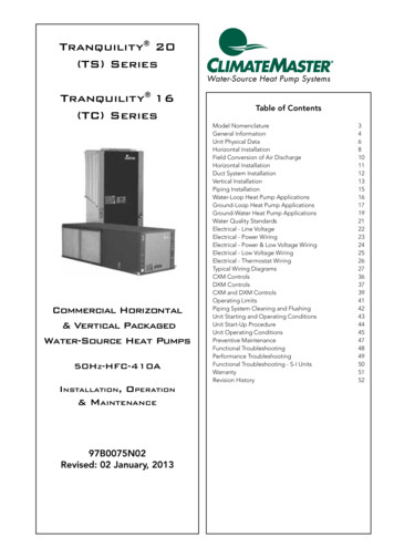
Tr o u b l e s h o o t i n g G u i d e - Tranquility D i g i t a l ( D X M 2 ) P a c k a g e d U n i t sR e v. : 4 A p r i l , 2 0 1 4Contactor ChartA-AMotor doesnot humContactorclosedBurnedcontactsOpen in lowvoltage circuitIncorrectwiringOpen motorwiringOpen overloadswitchHigh dischargepressure notequalizedLow linevoltageBurnt out oropen windingNon-condensibles inrefrigerant circuitMotor hums, cuts offon overload circuitbreaker or blowsfusesCompressor tight orstuckCheckcontactorBuzzingNormal voltageto coilLow voltageto coilContactor openContactor defective,jammed or hung upWrong gauge ofthermostat wireLow voltage fromtransformerNot buzzingLoosewireNo voltageto coilVoltageto coilNo powerto control circuitCoil opencircuitedVerifying Pump Feedback Signal1 2 3 SDOVRCOMFactory UseAlarmRelayCAO1 Gnd AO2 GndS1OffOn1 2 3 4 5 6 7 8S3OnOffT1 T2 T2 T3S2A0-1 A0-OffFault StatusU1A-B0-2 VDC with pump on3-4 VDC with pump offEnsure correct wiring on T1 Yellow,A0-2 White. If not, voltage may lookgood but pump may not operate.11
Tr o u b l e s h o o t i n g G u i d e - Tranquility D i g i t a l ( D X M 2 ) P a c k a g e d U n i t sR e v. : 4 A p r i l , 2 0 1 4Removing Powerhead on ¾-Inch Modulating ValveA-COn 3/4” valve, be sure that dip switchis moved up or toward center ofvalve and valve closes.For Proper Valve-to-Head AlignmentBefore r
Troubleshooting Guide - Tranquility Digital (DXM2) Packaged Units Rev.: 4 April, 2014 2 Geothermal Heat Pump Systems Troubleshooting ClimateMaster Tranquility Digital Packaged Heat Pumps is quite straightforward. Most problems relate to water fl ow. Either there isn’t enough water fl ow or the entering water temperature is improperlyFile Size: 2MBPage Count: 64