Transcription
Series 4600FHSC Fire Pumps & Packaged SystemsFILE NO:DATE:SUPERSEDES:DATE:F43.11May 26, 2008F43.11Dec. 15, 2007
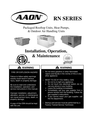
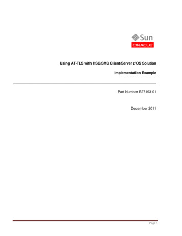
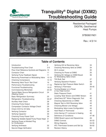
Series 4600FSeries 4600F - Truly SuperiorThe Series 4600F, drawing onover 100 years of pump designRecirculationexpertise and leadership, is thef External Water SealRecirculation Linesstate of the art in Horizontal SplitCase pumps. It meets or exceedsthe requirements of NFPA andtesting laboratories involved in fireCouplingprotection such as UL, ULC, & FM.fUL Listed close-coupled couplingThe family of pumps capitalize onthe “Tilted Parting” concept tominimize turbulence at the eye ofthe impeller by its straight laminarapproach, thus maximizingefficiency. The family wasdesigned with commonality ofparts, low installation cost, andease of maintenance objectives.The pumps’ compact sizes areideally suited for space savingpackages and retrofit applications.Stuffing Box HousingfSelf contained CombinationBearing & Seal Housingf Permits packing change-outwithout having to be removedDrip ContainmentfFitted with drain connectionCasing Wear Ringf Replaceable Case Wear RingsfLocked to prevent rotation oraxial displacementf Impeller Wear Ring availableas an optionPump Casingf Designed to withstand the highpressure requirement typical infire protection
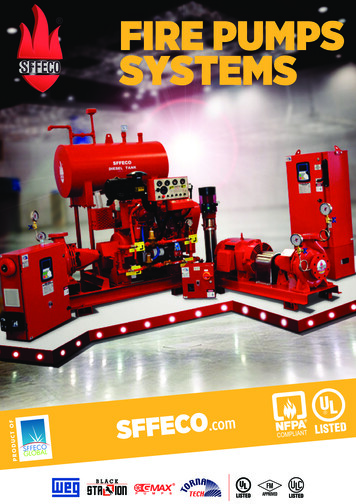
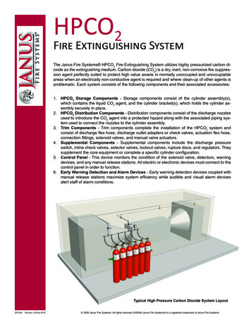
ImpellerShaft Sealing with PackingfHydraulically balanced double suctionfDynamically balancedfMinimum axial thrustfHigh efficiency throughout operating rangefThree-piece Split Gland standardfPacking replaceable withoutdisturbing wetted partsfStuffing Box Extensiondesigned for easy accessShaft SleevesfReplaceable bronze sleevesfProtects shaft throughoutStuffing BoxBearingsf Easy removal with bearing nutf Sealed, permanently greasedbearingsf Low Friction Lost Bearingf Maintenance freeTilted Parting Design CasingfPermits laminar approach to eye of ImpellerfLower NPSH requiredfLower pump profilefMinimum pump footprintfRemoveable rotating element without disturbing pipingfLow foot-mounted Casing to reduce vibrationsBearing Housing15 ANGLE CASINGf Removable withoutremoving top casingShaftfMinimum deflection for long bearing lifefMinimum vibrationsf Identical shaft and parts for left andright-hand drivesSuction andDischarge onsame center line
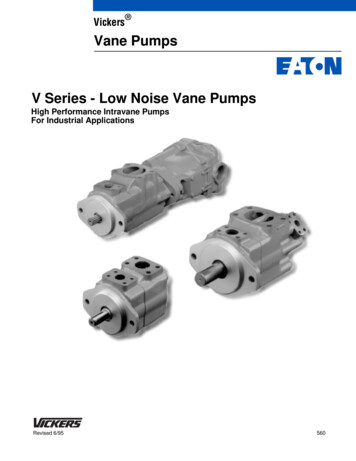
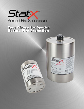
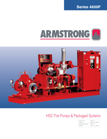
HSC Fire Pumps & Packaged SystemsJOCKEYCONTROLLERFIRE PUMPCONTROLLERFUELTANK28341213MAR910ST RONG116HorizontalFireSystemsWith years of experience in fire protectionindustry, Armstrong can supply fire pumpsystems with all necessary accessories readyfor site installation.GUARANTEED ADVANTAGESf Simplifies piping designf Single source unit responsibilityf A complete package that will meetNFPA-20 requirementsFIRE PUMP - ELECTRIC DRIVEN1. Pump/motor2. Fire pump controller(with optional transfer switch)3. Suction and discharge gauges4. Air release valve5. Casing relief valve (not shown)6. Jockey pump7. Common baseFeatures common to electric and dieselAccessories - (electric or diesel)Accessories - special for diesel or VFD7FIRE PUMP - DIESEL ENGINE DRIVEN1. Pump/engine assembled withfCooling systemfFuel systemfBattery systemfExhaust system2. Fire pump controller3. Suction and discharge gauges4. Air release valve6. Jockey pump7. Common baseACCESSORIES - ADDITIONAL (ELECTRIC OR DIESEL)8.9.10.11.Suction OS&Y gate valveDischarge butterfly valveCheck valveTest teeACCESSORIES - SPECIAL FOR DIESEL OR VFD12. Main relief valve13. Enclosed cone (not shown)
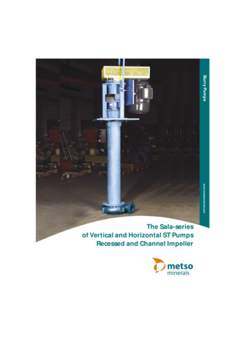
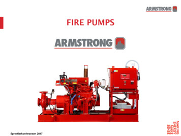
fFire Pump Coverage ChartElectrical 60 hzRated Capacity (L/min)1890285038004750570076009500114002503600 RPM17506 X 5 X 126 X 5 X 126 X 5 X 128 X 6 X 12.5150020012501508 X 6 X 105 X 4 X 105 X 4 X 106 X 5 X 108 X 6 X 151006 X 5 X 158 X 6 X 1510 X 8 X 146 X 5 X 15505 X 4 X 126 X 5 X 128 X 6 X 12.5100012 X 8 X 188 X 6 X 1012 X 8 X 1875012 X 8 X 1810 X 8 X 145008 X 6 X 000Rated Capacity (USGPM)Electrical 50 HzRated Capacity (L/min)1890285038003000 RPM25017506 X 5 X 1520015006 X 5 X 156 X 5 X 1510 X 8 X 1410 X 8 X 146 X 5 X 1215012506 X 5 X 1210008 X 6 X 12.58 X 6 X 12.55 X 4 X 1010010 X 8 X 116 X 5 X 108 X 6 X 105 X 4 X 10506 X 5 X 9.58 X 6 X 108 X 6 X 168 X 6 X 168 X 6 X 167508 X 6 X 108 X 6 X 1510 X 8 X 1412x8x185002755007501000125015002000Rated Capacity (USGPM)Note: Higher ranges may be available for diesel driven applications.2500Rated Head (kPa)Rated Head (psi)1500 RPMRated Head (kPa)Rated Head (psi)1800 RPM
fTypical SpecificationsHorizontal Fire Pump - Electric Motor Driven*Supply and install as indicated on plans one (1) fire pump system consisting of:1. FIRE PUMPOne Armstrong, SERIES 4600F, Size double suctionhorizontal split case fire pump listed by [Underwriters Laboratories ofCanada (ULC)], [Underwriters Laboratories Inc. (UL)] and/or [approved byFactory Mutual (FM)] having a capacity of USGPM for apressure boost of PSIG. Suction pressurePSIG.Pump casing shall be of cast iron, axially split with a 15 angle that willminimize NPSH requirements and dimensions. Lower half shall containsuction and discharge nozzles. Suction and discharge connections shall beon the same elevation. Top half and rotating element shall be removablewithout disturbing the piping. Casing shall be fitted with replaceable bronzewearing rings. Impeller shall be bronze, double suction, enclosed type fullybalanced and keyed to an alloy steel shaft. Shaft shall to be fitted withreplaceable bronze sleeves. Shaft shall be mounted in two dust tight deepgrooves, sealed, and permanently greased ball bearings.5. FIRE PUMP CONTROLLERThe fire pump controller shall be specifically approved for fire pump serviceby [ULC], [UL] and/or [FM]. The controller shall be of the combined manualand automatic stop, starting method, Modelas manufactured by . All equipment shall be enclosed in anapproved drip proof enclosure. The control equipment shall be completelyassembled, wired and tested at point of manufacture prior to shipment.Circuit breaker shall have an interrupting capacity of kAmps or awithstand rating of kAmps RMS.Water pressure switch shall be suitable for PSI working pressure.5A. FIRE PUMP CONTROLLER AND AUTOMATIC TRANSFERSWITCH COMBINATIONThe automatic transfer switch controller combination shall be approved by[UL], [ULC] and/or [FM], Model as manufacturedby . The automatic transfer switch and the pump controllershall each be mounted in separate enclosures, mechanically attached toform one unit and provide for protected interlock wiring.Bearings shall be mounted in cartridge type housing so that they shall bereplaceable without opening pump casing. Bearings shall be easilyremovable by rotating bearing removal nut. No special tools or bearing pullerare to be necessary.The automatic transfer switch shall be capable of automatic power transferfrom normal to alternate [generator] / [second utility]emergency power source in case of normal supply failure and automaticallyre-transfer after restoration of normal power conditions.Each stuffing box shall be fitted with a three piece bronze gland. Stuffing boxshall be fitted with a stuffing box extension to facilitate the packing ringsremoval. Packing rings shall be removable without disturbing wetted parts orthe pump bearings. Water seal recirculation lines made from non-corrodingmaterial shall be piped to pump volute.6. JOCKEY PUMP2. ELECTRIC MOTORThe fire pump shall be directly coupled through flexible coupling to ahorizontal electric motor with a maximum HP of atRPM, VOLT , PHASE CYCLE.Motor shall be UL Listed for fire pump service, open drip proof, standardefficiency with 1.15 service factor.The pump shall be supplied with the following accessories:fffOne (1) combination suction gauge 3½” dial type with ¼” cock and leverhandle.One (1) discharge gauge, 3½” dial type, with ¼” cock and lever handle.One (1) air release valve.One (1) casing pressure relief valve.4. OTHER ACCESSORIESPump shall be fitted with one (1) eccentric suction reducer and one (1)concentric discharge increaser, as required (by mechanical contractor) to fitNFPA20 recommended piping sizes.One (1) outside test header shall be supplied with one (1) set of x2½” hose valves with caps and chains.S. A. Armstrong Limited23 Bertrand AvenueToronto, OntarioCanada, M1L 2P3T: (416) 755-2291F (Main): (416) 759-91017. JOCKEY PUMP CONTROLLERThe jockey pump shall be controlled by an automatic jockey pumpcontroller model as manufactured by withfull voltage starter.8. MOUNTING AND TESTING3. MINIMUM FITTINGSfThe jockey pump shall be manufactured byModel for a capacity of USGPM and a pressureboost of PSIG. The jockey pump shall be driven by an [opendrip proof] [totally enclosed fan cooled] electric motor of HPRPM VOLT PHASE CYCLE.Armstrong Pumps Inc.93 East AvenueNorth Tonawanda, New YorkU.S.A., 14120-6594T: (716) 693-8813F: (716) 693-8970The fire pump shall be suitable for a maximum working pressure of. The fire pump shall be hydrostatically tested at twice themaximum working pressure for at least 5 minutes. The fire pump shall beperformance tested at rated speed. The fire pump shall furnish not less than150% of rated capacity at a pressure not less than 65% of rated head. Theshut-off total head of the fire pump should not exceed 140% of total ratedhead. A certified test curve, indicating the flow, head, power and efficiencyshall be supplied for the field acceptance test. The fire pump and electricmotor shall be base mounted and aligned at the pump manufacturer’sfactory. Final alignment shall be made after installation on site* Please refer to Armstrong Fire Pump Catalogue for Diesel Driven TypicalSpecifications.Armstrong Holden Brooke PullenWenlock WayManchesterUnited Kingdom, M12 5JLT: 44 (0) 161 223 2223F: 44 (0) 161 220 9660 S.A. Armstrong Limited 2008For Armstrong locations worldwide, please visit www.armstrongpumps.com
15.12.2007 · Please refer to Armstrong Fire Pump Catalogue for Diesel Driven Typical Specifications. Horizontal Fire Pump - Electric Motor Driven* * For Armstrong locations worldwide, please visit www.armstrongpumps.com S. A. Armstrong Limited 23 Bertrand Avenue Toronto, Ontario Canada, M1L 2P3 T: (416) 755-2291 F (Main): (416) 759-9101 Armstrong Pumps Inc .