Transcription
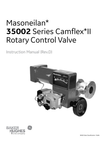
CONTROL VALVEHANDBOOKFifth Edition
Emerson Automation SolutionsFlow ControlsMarshalltown, Iowa 50158 USASorocaba, 18087 BrazilCernay, 68700 FranceDubai, United Arab EmiratesSingapore 128461 SingaporeNeither Emerson, Emerson Automation Solutions, nor any of their affiliated entities assumesresponsibility for the selection, use or maintenance of any product. Responsibility for properselection, use, and maintenance of any product remains solely with the purchaser and end user.The contents of this publication are presented for informational purposes only, and while everyeffort has been made to ensure their accuracy, they are not to be construed as warranties orguarantees, express or implied, regarding the products or services described herein or their useor applicability. All sales are governed by our terms and conditions, which are available uponrequest. We reserve the right to modify or improve the designs or specifications of such productsat any time without notice.Fisher is a mark owned by one of the companies in the Emerson Automation Solutions businessunit of Emerson Electric Co. Emerson and the Emerson logo are trademarks and service marksof Emerson Electric Co. All other marks are the property of their respective owners. 2005, 2019 Fisher Controls International LLC. All rights reserved.D101881X012/ Sept19
PrefaceControl valves are an increasingly vital component of modern manufacturing aroundthe world. Properly selected and maintained control valves increase efficiency,safety, profitability, and ecology.The Control Valve Handbook has been a primary reference since its first printing in1965. This fifth edition presents vital information on control valve performance andthe latest technologies.Chapter 1 offers an introduction to control valves, including definitions for commoncontrol valve and instrumentation terminology.Chapter 2 develops the vital topic of control valve performance.Chapter 3 covers valve and actuator types.Chapter 4 describes digital valve controllers, analog positioners, boosters, and othercontrol valve accessories.Chapter 5 is a comprehensive guide to selecting the best control valve for anapplication.Chapter 6 addresses the selection and use of special control valves.Chapter 7 explains desuperheaters, steam conditioning valves, and turbine bypasssystems.Chapter 8 details typical control valve installation and maintenance procedures.Chapter 9 contains information on control valve standards and approval agenciesacross the world.Chapter 10 identifies isolation valves and actuators.Chapter 11 covers discrete automation.Chapter 12 discusses various process safety instrumented systems.Chapter 13 provides useful tables of engineering reference data.Chapter 14 includes piping reference data.Chapter 15 is a handy resource for common conversions.The Control Valve Handbook is both a textbook and a reference on the strongest linkin the control loop: the control valve and its accessories. This book includes extensiveand proven knowledge from leading experts in the process control field, includingcontributions from the ISA.
Table of Contents
Control Valve Handbook Table of ContentsChapter 1: Introduction to Control Valves. 141.1 What is a Control Valve?.151.2 Sliding-Stem Control Valve Terminology.151.3 Rotary Control Valve Terminology.211.4 Control Valve Functions and Characteristics Terminology 231.5 Process Control Terminology.25Chapter 2: Control Valve Performance. 322.1 Process Variability.332.1.1 Deadband. 352.1.1.1 Causes of Deadband.352.1.1.2 Effects of Deadband.362.1.1.3 Performance Tests.362.1.1.4 Friction.362.1.2 Actuator and Positioner Design. 372.1.3 Valve Response Time. 382.1.3.1 Dead Time.382.1.3.2 Dynamic Time.382.1.3.3 Solutions.392.1.3.4 Supply Pressure.402.1.3.5 Minimizing Dead Time.402.1.3.6 Valve Response Time.412.1.4 Valve Type and Characterization. 412.1.4.1 Installed Gain.432.1.4.2 Loop Gain.432.1.4.3 Process Optimization.442.1.5 Valve Sizing. 452.2 Economic Results.462.3 Summary.48Chapter 3: Valve and Actuator Types. 503.1 Control Valve Styles.513.1.1 Globe Valves. 513.1.1.1 Single-Port Valve Bodies.513.1.1.2 Post- and Port-Guided Valve Bodies.523.1.1.3 Cage-Style Valve Bodies.523.1.1.4 Double-Ported Valve Bodies.533.1.1.5 Three-Way Valve Bodies.533.1.2 Sanitary Valves. 543.1.3 Rotary Valves. 543.1.3.1 Butterfly Valve Bodies.543.1.3.2 Segmented Ball Valve Bodies.555
Control Valve Handbook Table of Contents3.1.3.3 High-Performance Butterfly Valve Bodies.553.1.3.4 Eccentric Plug Valve Bodies.563.1.3.5 Full-Port Ball Valve Bodies.573.1.3.6 Multi-Port Flow Selector.573.2 Control Valve End Connections.573.2.1 Screwed Pipe Threads. 573.2.2 Bolted Gasketed Flanges. 583.2.3 Welded End Connections. 583.2.4 Other Valve End Connections. 593.3 Valve Body Bonnets.593.3.1 Extension Bonnets. 603.3.2 Bellows Seal Bonnets. 613.4 Control Valve Packing.613.4.1 PTFE V-Ring. 623.4.2 Laminated and Filament Graphite. 623.4.3 U.S. Regulatory Requirements for Fugitive Emissions. 623.4.4 Global Standards for Fugitive Emissions. 633.4.5 Single PTFE V-Ring Packing. 653.4.6 ENVIRO-SEAL PTFE Packing. 653.4.7 ENVIRO-SEAL Duplex Packing. 673.4.8 ISO-Seal PTFE Packing. 673.4.9 ENVIRO-SEAL Graphite ULF. 673.4.10 HIGH-SEAL Graphite ULF. 673.4.11 ISO-Seal Graphite Packing. 673.4.12 ENVIRO-SEAL Graphite for Rotary Valves. 673.4.13 Graphite Ribbon for Rotary Valves. 673.4.14 Sliding-Stem Environmental Packing Selection. 673.4.15 Rotary Environmental Packing Selection. 693.5 Characterization of Cage-Guided Valve Bodies.693.6 Valve Plug Guiding.703.7 Restricted-Capacity Control Valve Trim.703.8 Actuators.713.8.1 Diaphragm Actuators. 713.8.2 Piston Actuators. 723.8.4 Rack-and-Pinion Actuators. 733.8.5 Electric Actuators. 73Chapter 4: Control Valve Accessories. 744.1 Environmental & Application Considerations.754.2 Positioners.754.2.1 Pneumatic Positioners. 756
Control Valve Handbook Table of Contents4.2.2 Analog I/P Positioners. 764.2.3 Digital Valve Controllers. 774.2.3.1 Diagnostics.774.2.3.2 Two-Way Digital Communication.784.3 I/P Transducers.784.4 Volume Boosters.784.5 Safety Instrumented Systems (SIS).804.5.1 Partial Stroke Testing. 804.6 Controllers.814.7 Position Transmitters.834.8 Limit Switches.834.9 Solenoid Valves.834.10 Trip Systems.844.11 Handwheels.84Chapter 5: Control Valve Sizing. 865.1 Control Valve Dimensions .885.1.1 Face-to-Face Dimensions for Flanged, Globe-Style Valves. 885.1.2 Face-to-Face Dimensions for Butt Weld-End, Globe-Style Valves 905.1.3 Face-to-Face Dimensions for Socket Weld-End, Globe-Style Valves 915.1.4 Face-to-Face Dimensions for Screwed-End, Globe-Style Valves 925.1.5 Face-to-Centerline Dimensions for Raised-Face, Globe-Style Angle Valves 925.1.6 Face-to-Face Dimensions for Separable Flange, Globe-Style Valves 935.1.7 Face-to-Face Dimensions for Flanged and Flangeless Rotary Valves 935.1.8 Face-to-Face Dimensions for Single Flange and Flangeless Butterfly Valves 945.1.9 Face-to-Face Dimensions for High-Pressure, Offset Butterfly Valves 945.2 Control Valve Seat Leakage Classifications.955.3 Class VI Maximum Seat Leakage Allowable.965.4 Control Valve Flow Characteristics.965.4.1 Flow Characteristics. 965.4.2 Selection of Flow Characteristics. 975.5 Valve Sizing.975.7 Equation Constants .995.8 Sizing Valves for Liquids.1005.8.1 Determining Piping Geometry Factor and Liquid Pressure-Recovery Factor 1005.8.2 Determining the Pressure Drop to Use for Sizing. 1015.8.3 Calculating the Required Flow Coefficient. 1015.8.4 Liquid Sizing Sample Problem. 1025.9 Sizing Valves for Compressible Fluids.1045.9.1 Determining Piping Geometry Factor and Pressure Drop Ratio Factor at Choked Flow 1057
Control Valve Handbook Table of Contents5.9.2 Determining Pressure Drop Ratio to Use for Sizing and Expansion Factor 1055.9.3 Calculating Flow Coefficient. 1055.9.4 Compressible Fluid Sizing Sample Problem No. 1. 1065.9.5 Compressible Fluid Sizing Sample Problem No. 2. 1075.10 Representative Sizing Coefficients.1095.10.1 Representative Sizing Coefficients for Single-Ported, Globe-Style Valves 1095.10.2 Representative Sizing Coefficients for Rotary Valves . 1105.11 Actuator Sizing.1115.11.1 Globe Valves. 1115.11.1.1 Unbalance Force.1115.11.1.2 Force to Provide Seat Load.1125.11.1.3 Packing Friction.1125.11.1.4 Additional Forces.1125.11.2 Actuator Force Calculations. 1145.12 Actuator Sizing for Rotary Valves.1145.12.1 Torque Equations. 1145.12.2 Breakout Torque. 1145.12.3 Dynamic Torque. 1145.13 Typical Rotary Valve Torque Factors.1155.13.1 Torque Factors for V-Notch Ball Valve with Composition Seal 1155.13.2 Torque Factors for Butterfly Valve with Composition Seal. 1155.13.2.1 Maximum Rotation.1155.14 Cavitation and Flashing.1165.14.1 Choked Flow Causes Flashing and Cavitation. 1165.14.2 Valve Selection for Flashing Service. 1175.14.3 Valve Selection for Cavitation Service. 1185.15 Noise Prediction.1185.15.1 Aerodynamic. 1185.15.2 Hydrodynamic. 1205.16 Noise Control.1205.17 Noise Summary.1235.18 Packing Selection.1245.18.1 Packing Selection Guidelines for Sliding-Stem Valves. 1255.18.2 Packing Selection Guidelines for Rotary Valves. 1265.19 Valve Body Materials.1275.19.1 Designations for Common Valve Body Materials. 1295.20 Pressure-Temperature Ratings.1305.20.1 Standard Class ASTM A216 Grade WCC Cast Valves. 1305.20.2 Standard Class ASTM A217 Grade WC9 Cast Valves. 1315.20.3 Standard Class ASTM A351 Grade CF3 Cast Valves. 1325.20.4 Standard Class ASTM A351 Grades CF8M and CG8M Valves 1338
Control Valve Handbook Table of Contents5.21 Non-Metallic Material Abbreviations.1355.22 Non-Destructive Test Procedures.1355.22.1 Magnetic Particle (Surface) Examination. 1355.22.2 Liquid Penetrant (Surface) Examination. 1365.22.3 Radiographic (Volumetric) Examination. 1365.22.4 Ultrasonic (Volumetric) Examination. 136Chapte 6: Special Control Valves. 1386.1 High-Capacity Control Valves.1396.2 Low-Flow Control Valves.1406.3 High-Temperature Control Valves.1406.4 Cryogenic Service Valves.1416.5 Valves Subjected to Cavitation and Fluids with Particulate 1416.6 Customized Characteristics, Noise-Abatement, and Cavitation-MitigationTrims.1426.7 Control Valves for Nuclear Service in the U.S.1426.8 Valves Subjected to Sulfide Stress Cracking.1436.8.1 Pre-2003 Revisions of NACE MR0175. 1436.8.2 NACE MR0175/ISO 15156. 1446.8.3 NACE MR0103. 145Chapter 7: Steam Conditioning. 1467.1 Understanding Desuperheating.1477.1.1 Technical Aspects of Desuperheating. 1477.2 Typical Desuperheater Designs.1507.2.1 Fixed-Geometry Nozzle Design. 1507.2.2 Variable-Geometry Nozzle Design. 1517.2.3 Self-Contained Design. 1517.2.5 Geometry-Assisted Wafer Design. 1527.3 Understanding Steam Conditioning Valves.1537.4 Steam Conditioning Valves.1537.4.1 Steam Attemperator. 1557.4.2 Steam Sparger. 1557.6 Turbine Bypass System Components.1567.6.1 Turbine Bypass Valves. 1567.6.2 Turbine Bypass Water Control Valves. 1567.6.3 Actuation. 157Chapter 8: Installation and Maintenance. 1588.1 Proper Storage and Protection.1599
Control Valve Handbook Table of Contents8.2 Proper Installation Techniques.1598.2.1 Read the Instruction Manual. 1598.2.2 Be Sure the Pipeline Is Clean. 1598.2.4 Use Good Piping Practices. 1608.2.5 Flushing/Hydro/Start-Up Trim. 1618.3 Control Valve Maintenance.1618.3.1 Reactive Maintenance. 1628.3.2 Preventive Maintenance. 1628.3.3 Predictive Maintenance. 1628.3.4 Using Control Valve Diagnostics. 1628.3.4.1 Instrument Air Leakage.1638.3.4.2 Supply Pressure.1638.3.4.3 Travel Deviation and Relay Adjustment.1638.3.4.4 Instrument Air Quality.1648.3.4.5 In-Service Friction and Friction Trending.1648.3.4.6 Other Examples.1648.3.5 Continued Diagnostics Development. 1648.4 Service and Repair Parts.1658.4.1 Recommended Spare Parts. 1658.4.2 Using Original Equipment Manufacturers (OEM) Parts. 1658.4.3 Consider Upgrades for the Valve Trim. 1658.5 Actuator Maintenance.1658.5.1 Spring-and-Diaphragm Actuators . 1658.5.2 Piston Actuators. 1668.5.3 Stem Packing. 1668.5.4 Seat Rings. 1668.5.4.1 Replacing Seat Rings.1668.5.4.2 Connections: Plug-to-Stem, Ball-to-Shaft, and Disk-to-Shaft.1678.5.5 Bench Set. 1678.5.6 Valve Travel. 167Chapter 9: Standards and Approvals. 1689.1 Control Valve Standards.1699.1.1 American Petroleum Institute (API).
The Control Valve Handbook has been a primary reference since its first printing in 1965. This fifth edition presents vital information on control valve performance and the latest technologies. Chapter 1 offers an introduction to control valves, including definitions for common control