Transcription
Autotrol Series 255 Valve / 440i ControlWater Conditioning Control SystemInstallation, Operation and Maintenance ManualOsmonics reserves the right to revise specifications and designs to improve products at any time without notice. 1999 OsmonicsPrinted in USAR-409 8/99 PN 1018075 Rev. C1
Table of ContentsIntroduction . 2Superior DesignSuperior OperationInstallation . 3Location SelectionWater Line ConnectionDrain Line ConnectionOverflow Line ConnectionElectrical ConnectionSpecial Features of Timer . 7ProblemPossible CauseSolutionAdjustment of Brine Control . 7How to Set the Salt Dial8. Control backwashes or purges atexcessively low or high rate.a. Incorrect drain controller used.b. Foreign matter affecting controller operation.a. Replace with correct size drain controller.b. Remove drain controller and clean ball and seat.9. Flowing or dripping water at drainor brine line after regeneration.a. Drain valve (5 or 6) or brine valve (1)held open by foreign matter or particle.b. Valve stem return spring weak.a. Manually operate valve stem to flushaway obstruction.b. Replace spring.10. Hard water leakage afterregenerationa. Improper regeneration.a. Repeat regeneration making certaincorrect salt dosage was set.b. Replace o-ring.c. Replace o-ring.d. Replace valve disc.Removing the Series 255Control Module for Servicing . 8Preventive Maintenance . 9Specifications . 10Pressure Graphs . 11Increasing the Length of theTransformer Cord . 5Flow Diagrams . 12Placing Conditioner into Operation . 5Replacement Parts . 14Adjustment of Timer . 6Troubleshooting . 18b. Leaking of external bypass valve.c. O-ring around riser pipe damaged.d. Leaking past bypass valve disc.Disinfection of Water Conditioners . 19IntroductionThe Series 255 control system combines designsimplicity with NORYL* construction to provide theuser with an uncommonly reliable appliance. Theinherent reliability of the system means a long life ofefficient, trouble-free, uninterrupted soft water luxury.Should maintenance become necessary, the Series 255control system offers a unique “separation” capabilityillustrated in this manual. Brining control valve built into system eliminatesneed for an external brine valve. Automatic drain flow controller is incorporated inthe system.Superior OperationOf interest to the owner and water conditioning dealerare the design and operation benefits detailed below. Superior Design Fewer parts than any control system of comparablefunction and most controls of lesser function. Single synchronous low voltage electric motorprovides all the power for the clock 440i timer andthe operation of the control. Program clock (timer) provides guest regenerationcapabilitiy. Control may be indexed manually with or withoutpower to its service or regeneration positions. Legendon timer face plate indicates control valve position. No moving parts in water stream means no closetolerance components subject to fouling. Thus, thesystem is especially effective on iron-bearing water. No dynamic seals that could cause leakagethrough wear or fatigue. Control accepts NORYL or brass manifold ormodular bypass valve without modification,offering complete versatility and easy plumbing forany installation. Direct acting system functions independently ofwater pressure. No pistons or diaphragms thatrequire a minimum water pressure to operate.Five-cycle operation provides for downflowservice, upflow backwash, downflow brining,downflow rinse, downflow purge (fast rinse). A sixthposition is included for timed refill of the brine tank.Valve discs are held closed by water pressureand therefore, are leak tight. The sealing forces areincreased as the water pressure is increased. Valveseats are in a vertical position, which is the designposition least vulnerable to plugging.System operation cannot get out of phase orsequence. Control always returns to a fixed serviceposition after regeneration regardless of where inthe regeneration cycle it was started.Bypass water is automatically available duringregeneration.Disinfection of Water ConditionersThe materials of construction of the modern waterconditioner will not support bacterial growth, nor willthese materials contaminate a water supply. However,the normal conditions existing during shipping, storageand installation indicate the advisability of disinfectinga conditioner after installation, before the conditioneris used to treat potable water. In addition, duringnormal use, a conditioner may become fouled withorganic matter, or in some cases, with bacteria fromthe water supply.2. Brine tank conditionersa. Backwash the conditioner, and add the requiredamount of hypochlorite solution to the brine wellof the brine tank. (The brine tank should havewater in it to permit the solution to be carried intothe conditioner.)b. Proceed with the normal regeneration.Calcium HypochloriteCalcium hypochlorite, 70% available chlorine, isavailable in several forms including tablets and granules. These solid materials may be used directly,without dissolving before use.Thus every conditioner should be disinfected afterinstallation, some will require periodic disinfectionduring their normal life, and in a few cases disinfectionwith every regeneration would be recommended.1. DosageDepending upon the conditions of use, the style ofconditioner, the type of ion exchanger, and the disinfectant available, a choice can be made among thefollowing methods.a. 2 grains (approximately 0.1 ounce) per cubic foot.2. Brine tank conditionersa. Backwash the conditioner and add the requiredamount of hypochlorite to the brine well of thebrine tank. (The brine tank should have water in itto permit the chlorine solution to be carried intothe conditioner.)Sodium or Calcium HypochloriteApplicationThese materials are satisfactory for use with polystyreneresins, synthetic gel zeolite, greensand and bentonites.b. Proceed with the normal regeneration.5.25% Sodium HypochloriteThese solutions are available under trade names such asClorox, Linco, Bo Peep, White Sail and Eagle BrandBleach. If stronger solutions are used, such as those soldfor commercial laundries, adjust the dosage accordingly.1. Dosagea. Polystyrene resin; 1.2 fluid ounce per cubic foot.* NORYL is a Trademark of General Electric Company2b. Non-resinous exchangers; 0.8 fluid ounce percubic foot.19
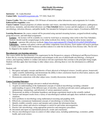
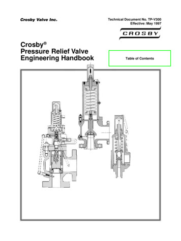
TroubleshootingInstallationThe technology upon which the Series 255 control is based is well established and proven in service over manyyears. However, should a problem or question arise regarding the operation of the system, the control can be veryeasily serviced. The control module can be quickly replaced or adjustments can be made at the installation. Forparts mentioned, refer to exploded views in the Replacement Parts section of this manual.All plumbing must conform to local codes.Not in BypassIn BypassInspect unit carefully for carrier shortage or shippingdamage.Location SelectionProblemPossible CauseSolution1. Control will not regenerateautomatically.a. Transformer or motor not connected.b. Defective timer motor.c. Skipper pins not down on timer skipperwheel.d. Binding in gear train of timer.a. Connect power.b. Replace motor.c. Depress pins for days regenerationrequired.d. Replace timer.2. Control regenerates at wrongtime of day.a. Time set incorrectly.a. Correct time setting accordingto instructions.3. Control will not draw brine.a. Low water pressure.b. Restricted drain line.c. Injector plugged.d. Injector defective.e. Valve disc 2 and/or 3 not closed.a. Set pump to maintain 20 psi at softener.b. Change drain to remove restriction.c. Clean injector and screen.d. Replace injector.e. Remove foreign matter from disc and checkdisc for closing by pushing in on stem.Replace if needed.f. Put control momentarily into brine/slow rinse.Replace or repair air check if needed.g. Turn to horizontal position.f. Air check valve closes prematurely.g. Timer locking pin not horizontal4. Brine tank overflow.a. Brine valve disc 1 being held openby foreign matter.b. Uncontrolled brine refill flow rate.c. Valve disc 2 not closed during brinedraw causing brine refill.d. Air leak in brine line to air check.e. Improper drain control for injector.f. Drain control clogged with resin orother debris.a. Manually operate valve stem to flushaway obstruction.b. Remove brine control to clean ball andseat.c. Flush out foreign matter holding discopen by manually operating valve stem.d. Check all connections in brine line forleaks. Refer to instructions.e. Too small of a drain control with a "B" or"C" injector will reduce draw rates. SeePressure Graphs.f. Clean drain control.1. The distance between the unit and a drain shouldbe as short as possible.2. If it is likely that supplementary water treatingequipment will be required, make certain adequateadditional space is available.WaterConditioner3. Since salt must be added periodically to the brinetank, the location should be easily accessible.Figure 1 Autotrol Series 256 Bypass Valve4. Do not install any unit closer to a water heater thana total run of 10 feet (3 m) of piping between theoutlet of the conditioner and the inlet to the heater.Water heaters can sometimes overheat to theextent they will transmit heat back down the coldpipe into the unit control valve.Not in BypassHot water can severely damage the conditioner.A 10 foot (3 m) total pipe run, including bends,elbows, etc., is a reasonable distance to helpprevent this possibility. A positive way to preventhot water from flowing from heat source to theconditioner, in the event of a negative pressuresituation, is to install a check valve in the soft waterpiping from the conditioner. If a check valve isinstalled, make certain the water heating unit isequipped with a properly rated temperature andpressure safety relief valve. Also, be certain thatlocal codes are not violated.WaterConditioner6. Intermittent or irregular brine draw.7. No conditioned water afterregeneration.a. Foreign matter in controller causingincorrect flow rates.b. Defective controller.a. Remove brine control and flush outforeign matter. Manually position controlto brine/slow rinse to clean controller(after so doing position control to “purge”to remove brine from tank)b. Replace brine control.a. Low water pressure.b. Defective injector.a. Set pump to maintain 20 psi at softener.b. Replace injector.a. No salt in brine tank.b. Injector plugged.c. Air check valve closes prematurely.a. Add salt to brine tank.b. Clean injector and screen.c. Put control momentarily into brine/slow rinse.Replace or repair air check if needed.In BypassWaterConditionerFigure 2 Typical globe valve bypass systemDrain Line Connection5. Do not locate unit where it or its connections(including the drain and overflow lines) will ever besubjected to room temperatures under 34 F (1 C)or over 120 F (49 C).1. Ideally located, the unit will be above and not morethan 20 feet (6.1 m) from the drain. For such installations, using an appropriate adapter fitting (notsupplied), connect 1/2 inch (1.3 cm) plastic tubingto the drain line connection of the control valve.6. Do not install unit near acid or acid fumes.7. The use of resin cleaners in an unvented enclosureis not recommended.2. If the unit is located more than 20 feet (6.1 m) fromdrain, use 3/4-inch (1.9 cm) tubing for runs up to 40feet (12.2 m). Also, purchase appropriate fitting toconnect the 3/4-inch tubing to the 1/2-inch NPTdrain connection.Water Line Connection5. System using more or less saltthan salt dial setting.WaterConditionerThe installation of a bypass valve system is recommendedto provide for occasions when the water conditioner mustbe bypassed for hard water or for servicing.3. If the unit is located where the drain line must beelevated, you may elevate the line up to 6 feet (1.8 m)providing the run does not exceed 15 feet (4.6 m)and water pressure at conditioner is not less than 40psi (2.76 bar). You may elevate an additional 2 feet(61 cm) for each additional 10 psi (.69 bar).The most common bypass systems are the AutotrolSeries 256 Bypass Valve (Figure 1) and plumbed-inglobe valves (Figure 2). Though both are similar infunction, the 256 Autotrol Bypass offers simplicity andease of operation.4. Where the drain line is elevated but empties into adrain below the level of the control valve, form a 7inch (18 cm) loop at the far end of the line so thatthe bottom of the loop is level with the drain lineconnection. This will provide an adequate siphontrap.5. Where the drain empties into an overhead sewerline, a sink-type trap must be used.183
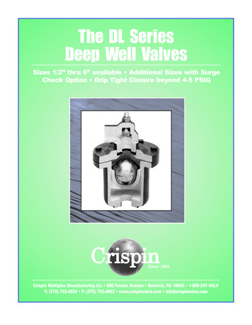
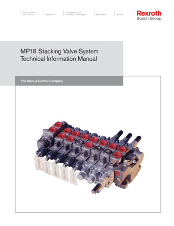
Bypass Valve440i TimerImportantOverflowFittingInstalledNever insert drain line into a drain, sewer line ortrap. Always allow an air gap between the drainline and the wastewater to prevent the possibilityof sewage being back-siphoned into conditioner.PartNo.DescriptionQty.Skipper Wheel 1006091Screw, No. 6 x 1/2 in241006601Bowed Washer151031756Tripper Arm otor, 12 Volt, 60 JapaneseNorth AmericanAustralianBritishEuropeanCode1Brine TankConnect 1/2 in (1.3 cm) I.D.Tubing or Hose and Runto DrainRight WayFigure 49Low Voltage TransformerFigure 3Only use the included transformer for powering the440i timer. Connect the plug of the transformer secondary cable to the mating socket at the rear of thetimer housing on the motor.Note: Standard commercial practices have beenexpressed here. Local codes may require changes tothese suggestions.*1000907Be certain that the transformer is plugged into a correctvoltage source that is not controlled by a wall switch.Brine Line ConnectionIt will be necessary to install the brine tube and line to afitting installed on the air check. Teflon* tape allthreaded connections.Transformer Extension Cord15 ft. (4.6 m)CodeCodePartNo.11040277Overflow Line Connection1040278In the absence of a safety overflow and in the event ofa malfunction, the BRINE TANK OVERFLOW will direct“overflow” to the drain instead of spilling on the floorwhere it could cause considerable damage. This fittingshould be on the side of the cabinet or brine tank.104028110402821040279To connect overflow, locate hole on side of brine tank.Insert overflow fitting (not supplied) into tank andtighten with plastic thumb nut and gasket as shown(Figure 4). Attach length of 1/2-inch (1.3 cm) I.D. tubing(not supplied) to fitting and run to drain. Do not elevateoverflow line higher than 3 inches (7.6 cm) belowbottom of overflow fitting. Do not tie into drain line ofcontrol unit. Overflow line must be a direct, separateline from overflow fitting to drain, sewer or tub. Allowan air gap as per drain line instructions (Figure s Body Assembly121040524Bypass Installation Kit1*1034301Rotor Replacement*1034302Kit, Service, Rotor Seals and Two Clips*103430324pk, Rotor ClipsTube Adapter KitsPartCode1No.DescriptionQty.*10016063/4 Inch Copper Tube Adapter Kit1*10016701 Inch Copper Tube Adapter Kit1*100160822mm Copper Tube Adapter Kit1*100160928mm Copper Tube Adapter Kit1*10016133/4 Inch CPVC Tube Adapter Kit1*10016141 Inch CPVC Tube Adapter Kit1*100161525mm CPVC Tube Adapter Kit1*10017693/4 Inch NPT Plastic Pipe Adapter Kit 1*10016031 Inch NPT Plastic Pipe Adapter Kit 1DescriptionQty.*10016043/4 Inch BSPT Plastic Pipe Adapter Kit 1Piping Boss Kit(Includes Hardware):3/4 in NPT, Brass,3/8 in NPT Drain1 in NPT, Brass,1/2 in NPT Drain3/4 in BSPT, Brass,3/8 in BSPT Drain1 in BSPT, Brass,1/2 in BSPT Drain3/4 in NPT, Noryl,1/2 in NPT Drain1 in NPT, Noryl,1/2 in NPT Drain3/4 in BSPT, Noryl,1/2 in BSPT Drain1 in BSPT, Noryl,1/2 in BSPT Drain1*10016051 Inch BSPT Plastic Pipe Adapter Kit 1*10016113/4 Inch BSPT Brass Pipe Adapter Kit 1**100161010016121 Inch NPT Brass Pi0pe Adapter Kit 11 Inch BSPT Brass Pipe Adapter Kit 1Piping Boss Installation Kit1* Not Shown* Teflon is a registered trademark of E.I. Dupont & Co.DescriptionService Kits:Piping BossBe sure all fittings and connections are tight so thatpremature checking does not take place. Prematurechecking is when the ball in the air check falls to thebottom before all brine is drawn out of the brine tank.See Placing Conditioner into Service section.PartNo.17
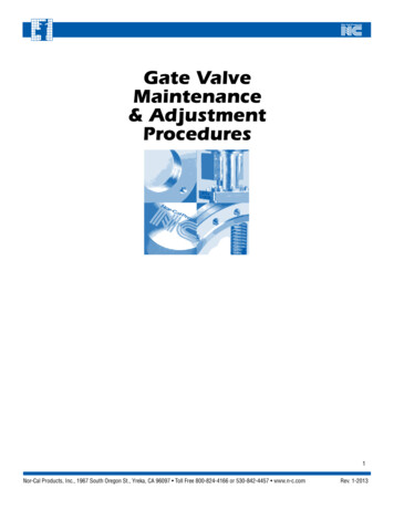
440i TimerIncreasing the Length of theTransformer Cord1After all previous steps have been completed, the unitis ready to be placed into operation. Follow thesesteps carefully.If it is necessary to extend the length of the transformercord, an optional 15 foot (4.6 m) extension is available,(see Figure 5) or the cord may be spliced as follows:42Placing Conditioner into Operation31. Remove control valve cover (Figure 10A).1. Strip insulation from wire 5/16-inch(8mm) from wireend.Note: The following steps will require turning thepointer knob, (Figure 8), to various positions. Inserta wide blade screwdriver into arrow slot in pointerknob and press in firmly. With knob held in, rotateCOUNTERCLOCKWISE only until arrow or knobpoints to desired position. (Rotation is made mucheasier if you grasp the camshaft with your free handand turn it at the same time.) Then permit knob tospring back out.2. Insert stripped wire into barrel of connector andcrimp. For best results, crimp twice per wire asshown (Figure 6).9Splice connectors or extension wire is not supplied.They are available at hardware or electrical stores.8372. Insert screwdriver into slot in pointer knob, (Figure 8).Press in and rotate knob COUNTERCLOCKWISEuntil arrow points directly to the word BACKWASH.653. Fill resin tank with water.A. With water supply off, place the bypass valve(s)into the "not in bypass" position.B Y PA S SB. Open water supply valve very slowly to approximately the 1/4 open position.Figure 5B Y PA S SBypass ValveImportantIf opened too rapidly or too far, resin may belost. In this position, you should hear airescaping slowly from the drain line.2C. When all of the air has been purged from thetank(water begins to flow steadily from the drain),open the water supply valve all the way.D. Allow water to run to drain until clear.Splice Connector(22-18 AWG)1E. Turn off water supply and let the unit stand forabout 5 minutes. This will allow all trapped air toescape from the tank.50 feet(15.24m) maximum, 18 AWG solidor stranded insulated copper wire.Figure 6Piping BossNote: Do not use pipe joint compoundwhen threading pipe into the Noryl pipingboss. Use only Teflon pipe tape. Do notovertighten pipe into Noryl piping boss.1* Teflon is a registered Trademark of E. I.Dupont Nemours and Co.21654. Add water to brine tank (initial fill).With a bucket or hose, add approximately 4 gallons(15 liters) of water to brine tank. If the tank has asalt platform above the bottom of the tank, addwater until the level is approximately 1inch (25 mm)above the platform.
Adjustment of TimerControl ValveCheckBallSkipper WheelSkipper 026103296931030501Camshaft Bearing1BACKWASH41031391Timer Locking Pin1START51000226Screen/Cap Assemblywith 1000215Drain Control Assemblywith O-Rings:No. 7 (1.2 gpm; 4.5 lpm)No. 8 (1.6 gpm; 6.1 lpm)No. 9 (2.0 gpm; 7.6 lpm)No. 10 (2.5 gpm; 9.5 lpm)No. 12 (3.5 gpm; 13.2 lpm)No. 13 (4.1 gpm; 15.5 lpm)**No. 14 (4.8 gpm; 18.2 lpm)**1030502Ball, Flow 066Kits:New to Old Aircheck Adapter231001404O
Single synchronous low voltage electric motor provides all the power for the clock 440i timer and the operation of the control. Program clock (timer) provides guest regeneration capabilitiy. Control may be indexed manually with or without power to its service or regeneration po