Transcription
IBMERserverpSeries 610 Model 6C1 and Model 6E1User’s GuideSA38-0598-01
IBMERserverpSeries 610 Model 6C1 and Model 6E1User’s GuideSA38-0598-01
Second Edition (February 2002)Before using this information and the product it supports, read the information in “Safety Notices” on page xi,Appendix A, “Environmental Notices” on page 161, and Appendix B, “Notices” on page 163.A reader’s comment form is provided at the back of this publication. If the form has been removed, address commentsto Information Development, Department H6DS-905-6C006, 11400 Burnet Road, Austin, Texas 78758-3493. To sendcomments electronically, use this commercial internet address: aix6kpub@austin.ibm.com. Any information that yousupply may be used without incurring any obligation to you. International Business Machines Corporation 2001, 2002. All rights reserved. Note to U.S. Government Users-- Documentation related to restricted rights -- Use, duplication or disclosure is subject to restrictions set forth is GSAADP Schedule Contract with IBM Corp.
ContentsSafety Notices . . . .Rack Safety Instructions .Electrical Safety . . .Laser Safety InformationLaser Compliance . .Data Integrity and Verification . xi. xi. xii. xiii. xiii. xvAbout This Book . . . . . . . . . . . . . . . . . . . . . . xviiISO 9000 . . . . . . . . . . . . . . . . . . . . . . . . . xviiOnline Publications . . . . . . . . . . . . . . . . . . . . . . xviiRelated Publications . . . . . . . . . . . . . . . . . . . . . . xviiErgonomic Information . . . . . . . . . . . . . . . . . . . . . xviiiTrademarks . . . . . . . . . . . . . . . . . . . . . . . . xviiiChapter 1. IntroducingSystem Features . .Bus Architecture . .Processors . . .Memory . . . .Media Drives . . .Other Drives . . .Power supply . . .Keyboard . . . .Mouse . . . . .Operator Panel . .Input/Output Ports .Security Features .Front View. . . .Rear View . . . .Operator Panel . .the System. . . . . . . . . . . . . . . . . . . . . . . . . . . . . . . . . . . . . . . . . . . . . .Chapter 2. Using the System . . .Starting the System Unit . . . . .Stopping the System Unit. . . . .Reading the Operator Panel Display .Operator Panel . . . . . . .Attention LED and Lightpath LEDs .Operator Panel Display . . . .Indicator Panel . . . . . . .Component LEDs . . . . . .Reporting the Problem . . . .Using the Keyboards . . . . . .Using the Three-Button Mouse . .Handling the Mouse Correctly . .Caring for the Mouse . . . . .Cleaning the Mouse . . . . .1111112222222357. 9. 9. 9. 9. . . . . . . . . . . . . . . . 10. . . . . . . . . . . . . . . . 11. . . . . . . . . . . . . . . . 11. . . . . . . . . . . . . . . . 12. . . . . . . . . . . . . . . . 13. . . . . . . . . . . . . . . . 14. . . . . . . . . . . . . . . . 15. . . . . . . . . . . . . . . . 16. . . . . . . . . . . . . . . . 16. . . . . . . . . . . . . . . . 16. . . . . . . . . . . . . . . . 17iii
Using the 3.5-Inch Diskette Drive . . . . . .Write-Protecting 3.5-Inch Diskettes . . . .Loading and Unloading the 3.5-Inch Diskette .Using the CD-ROM Drive . . . . . . . .Front View of CD-ROM Drive . . . . . .Understanding the Status Lights . . . . .Handling Compact Discs . . . . . . .Other Handling Considerations . . . . .Loading a Compact Disc . . . . . . .Opening the Tray Manually . . . . . . .Playing an Audio CD . . . . . . . . .Using the Service Processor and Service DirectorService Processor . . . . . . . . . .Service Director . . . . . . . . . . . . . . . . . . . . . . . . . . . . . . . .Features. . . . .Chapter 3. Using the Service Processor. . . . . . .Service Processor Menus . . . . . . . . . . . .Service Processor Menu Inactivity . . . . . . . .Accessing Service Processor Menus Locally . . . . .Accessing Service Processor Menus Remotely . . . .Saving and Restoring Service Processor Settings . . .General User Menu . . . . . . . . . . . . . .Privileged User Menus . . . . . . . . . . . . .Main Menu . . . . . . . . . . . . . . . .Service Processor Setup Menu . . . . . . . . .Passwords . . . . . . . . . . . . . . . .Serial Port Snoop Setup Menu . . . . . . . . .System Power Control Menu . . . . . . . . . .System Information Menu . . . . . . . . . . .Language Selection Menu . . . . . . . . . . .Call-In/Call-Out Setup Menu . . . . . . . . . .Modem Configuration Menu . . . . . . . . . .Serial Port Selection Menu . . . . . . . . . . .Serial Port Speed Setup Menu . . . . . . . . .Telephone Number Setup Menu . . . . . . . . .Call-Out Policy Setup Menu . . . . . . . . . .Customer Account Setup Menu . . . . . . . . .Call-Out Test . . . . . . . . . . . . . . .System Power-On Methods . . . . . . . . . . .Service Processor Call-In Security . . . . . . . . .Service Processor Reboot/Restart Recovery . . . . . .Boot (IPL) Speed . . . . . . . . . . . . . .Failure During Boot Process . . . . . . . . . .Failure During Normal System Operation . . . . . .Service Processor Reboot/Restart Policy Controls . . .Processor Boot-Time Deconfiguration (CPU Repeat Gard)Memory Boot-Time Deconfiguration (Memory Repeat Gard)Service Processor System Monitoring - Surveillance . . .System Firmware Surveillance. . . . . . . . . .Operating System Surveillance . . . . . . . . .ivUser’s 15151
Call Out . . . . . . . . . . . .Console Mirroring . . . . . . . . . .System Configuration for Console MirroringService Processor Firmware Updates . . .Service Processor Error Log . . . . . .Service Processor Operational Phases . . .Pre-Standby Phase . . . . . . . .Standby Phase . . . . . . . . . .Bring-Up Phase . . . . . . . . .Run-time Phase . . . . . . . . .Service Processor Procedures in Service Mode.5253535454555555565657Chapter 4. Using System Management Services .Graphical System Management Services . . . .Config. . . . . . . . . . . . . . . .Multiboot . . . . . . . . . . . . . . .Utilities . . . . . . . . . . . . . . .Password . . . . . . . . . . . . .Spin Delay . . . . . . . . . . . . .Error Log. . . . . . . . . . . . . .RIPL . . . . . . . . . . . . . . .SCSI ID . . . . . . . . . . . . . .Firmware Update . . . . . . . . . . . .Firmware Recovery . . . . . . . . . .Text-Based System Management Services . . .Select Language . . . . . . . . . . . .Change Password Options . . . . . . . . .Set Privileged-Access Password . . . . . .Unattended Start Mode . . . . . . . . .View Error Log . . . . . . . . . . . . .Setup Remote IPL (Initial Program Load) . . . .Change SCSI Settings . . . . . . . . . .Select Console . . . . . . . . . . . . .Select Boot Options . . . . . . . . . . .Select Boot Device . . . . . . . . . .Configure Nth Boot Device . . . . . . . .View System Configuration Components . . . .System/Service Processor Firmware Update . . .Firmware Recovery . . . . . . . . . . 19292.939393939494Chapter 5. Using the Standalone and Online Diagnostics . . . . .Standalone and Online Diagnostics Operating Considerations . . . . .Selecting a Console Display . . . . . . . . . . . . . . .Identifying the Terminal Type to the Diagnostics Programs . . . . .Undefined Terminal Types . . . . . . . . . . . . . . . .Running Online Diagnostics from CD-ROM . . . . . . . . . .Running Standalone Diagnostics from a Network Installation ManagementServer . . . . . . . . . . . . . . . . . . . . . .Running Online Diagnostics . . . . . . . . . . . . . . . .Running the Diagnostics from a TTY Terminal . . . . . . . . . . . . . . . .(NIM). . . .Contents. 94. 98. 99v
Online Diagnostics Mode of Operation . . . . . . . . . .Running the Online Diagnostics in Service Mode (Service ModeRunning the Online Diagnostics in Concurrent Mode . . . .Running the Online Diagnostics in Maintenance Mode . . .Standalone Diagnostic Operation . . . . . . . . . . .Running the Standalone Diagnostics . . . . . . . . .viUser’s Guide. .IPL) . . . . . 99. 99. 100. 101. 102. 102Chapter 6. Introducing Tasks and Service Aids . . . . . . . . . .Tasks . . . . . . . . . . . . . . . . . . . . . . . .Add Resource to Resource List . . . . . . . . . . . . . . . .AIX Shell Prompt . . . . . . . . . . . . . . . . . . . .Analyze Adapter Internal Log. . . . . . . . . . . . . . . . .Backup and Restore Media . . . . . . . . . . . . . . . . .Certify Media . . . . . . . . . . . . . . . . . . . . . .Change Hardware Vital Product Data . . . . . . . . . . . . . .Configure Dials and LPF Keys . . . . . . . . . . . . . . . .Configure ISA Adapter . . . . . . . . . . . . . . . . . . .Configure Reboot Policy . . . . . . . . . . . . . . . . . .Configure Remote Maintenance Policy . . . . . . . . . . . . .Configure Ring Indicate Power On Policy. . . . . . . . . . . . .Configure Surveillance Policy. . . . . . . . . . . . . . . . .Create Customized Configuration Diskette . . . . . . . . . . . .Delete Resource from Resource List . . . . . . . . . . . . . .Disk Maintenance . . . . . . . . . . . . . . . . . . . .Disk to Disk Copy . . . . . . . . . . . . . . . . . . .Display/Alter Sector . . . . . . . . . . . . . . . . . . .Display Configuration and Resource List . . . . . . . . . . . . .Display Firmware Device Node Information . . . . . . . . . . . .Display Hardware Error Report . . . . . . . . . . . . . . . .Display Hardware Vital Product Data . . . . . . . . . . . . . .Display Machine Check Error Log . . . . . . . . . . . . . . .Display Microcode Level . . . . . . . . . . . . . . . . . .Display or Change Bootlist . . . . . . . . . . . . . . . . .Display or Change Diagnostic Run-Time Options . . . . . . . . . .Display Previous Diagnostic Results . . . . . . . . . . . . . .Display Resource Attributes . . . . . . . . . . . . . . . . .Display Service Hints . . . . . . . . . . . . . . . . . . .Display Software Product Data . . . . . . . . . . . . . . . .Display System Environmental Sensors . . . . . . . . . . . . .Examples . . . . . . . . . . . . . . . . . . . . . .Display Test Patterns . . . . . . . . . . . . . . . . . . .Download Microcode . . . . . . . . . . . . . . . . . . .Download Microcode to PCI SCSI RAID Adapter . . . . . . . . .Download Microcode to Disk Drive Attached to a PCI SCSI RAID AdapterDownload Microcode to a PCI FC-AL Adapter . . . . . . . . . .Download Microcode to DVD-RAM Attached to a PCI SCSI Adapter . . .Download Microcode to Disk Attached to PCI SCSI Adapter . . . . .Download Microcode to Other Devices . . . . . . . . . . . .Fibre Channel RAID Service Aids . . . . . . . . . . . . . . .Flash SK-NET FDDI Firmware . . . . . . . . . . . . . . . 121121121121121122122122123124
Format Media . . . . . . . . . . . . . . .Hardfile Attached to SCSI Adapter (non-RAID) . . .Hardfile Attached to PCI SCSI RAID Adapter . . .Optical Media . . . . . . . . . . . . . .Diskette Format . . . . . . . . . . . . .Gather System Information . . . . . . . . . .Generic Microcode Download . . . . . . . . .Hot Plug Task . . . . . . . . . . . . . . .PCI Hot Plug Manager . . . . . . . . . . .SCSI Hot Swap Manager . . . . . . . . . .RAID Hot Plug Devices . . . . . . . . . .Local Area Network Analyzer . . . . . . . . . .Log Repair Action . . . . . . . . . . . . .Periodic Diagnostics . . . . . . . . . . . .PCI RAID Physical Disk Identify . . . . . . . . .Process Supplemental Media . . . . . . . . .Run Diagnostics . . . . . . . . . . . . . .Run Error Log Analysis . . . . . . . . . . .Run Exercisers . . . . . . . . . . . . . .Exerciser Commands (CMD) . . . . . . . . .Abbreviations . . . . . . . . . . . . . .Memory Exerciser . . . . . . . . . . . .Tape Exerciser . . . . . . . . . . . . .Diskette Exerciser . . . . . . . . . . . .CD-ROM Exerciser . . . . . . . . . . . .Save or Restore Hardware Management Policies . . .SCSI BUS Analyzer . . . . . . . . . . . . .SCSI Tape Drive Service Aid . . . . . . . . . .Spare Sector Availability . . . . . . . . . . .SSA Service Aid . . . . . . . . . . . . . .System Fault Indicator . . . . . . . . . . . .System Identify Indicator . . . . . . . . . .Update Disk-Based Diagnostics . . . . . . . . .Update System or Service Processor Flash . . . . .7135 RAIDiant Array Service Aid . . . . . . . .Adapter Microcode Download . . . . . . . .Physical Disk Microcode Download. . . . . . .Physical Disk Format . . . . . . . . . . .Physical Disk Certify . . . . . . . . . . .Physical Disk Identify . . . . . . . . . . .7318 Serial Communications Network Server Service 138139140140141141141141141Chapter 7. Using the System Verification ProcedureStep 1. Considerations before Running This ProcedureStep 2. Loading the Diagnostics. . . . . . . .Step 3. Running System Verification . . . . . .Step 4. Additional System Verification . . . . . .Step 5. Stopping the Diagnostics . . . . . . .143143143144144145Chapter 8. Hardware Problem Determination. 147.Contentsvii
Problem Determination Using the Standalone or Online Diagnostics .Step 2. . . . . . . . . . . . . . . . . . . . .Problem Determination When Unable to Load Diagnostics . . . . 147. 147. 154Chapter 9. Repair Action. 159Appendix A. Environmental Notices.Product Recycling and Disposal . . .Environmental Design . . . . . .Acoustical Noise Emissions . . . .Declared Acoustical Noise Emissions.Appendix B. Notices . 163a TTY Terminal. . . . . . . . . . . . . . . .Appendix C. General Attributes Required When UsingAdditional Communication Attributes . . . . . . .Additional Keyboard Attributes . . . . . . . . .Additional Printer Attributes . . . . . . . . . .Appendix D. Firmware Updates . .Checking the Current Firmware LevelsUpdating System Firmware . . . .Appendix E. Service Processor SetupService Processor Setup Checklist . .Testing the Setup . . . . . . .Testing Call-In . . . . . . .Testing Call-Out . . . . . . .Serial Port Configuration . . . .and. . . . . .User’s Guide165166167168. 169. 169. 169Test. . . . . .171171172172172173. . . . . . . . . . . . . . . . . . . . . . . . . . . . . . .Configuration Files. . . . . . . . . . . . . . . . . . . . . . . . . . . . . . . . . . . . . . . . . . . . . . . . . . . . . . . . . . . . . . . . . . . . . . . . . . . . . . 83185187Appendix F. Modem Configurations . . . . .Sample Modem Configuration Files . . . . .Generic Modem Configuration Files . . . .Specific Modem Configuration Files . . . .Configuration File Selection . . . . . . . .Examples for Using the Generic Sample ModemCustomizing the Modem Configuration Files . .IBM 7852-400 DIP Switch Settings . . . . .Xon/Xoff Modems . . . . . . . . . .Ring Detection . . . . . . . . . . .Terminal Emulators . . . . . . . . . .Recovery Procedures . . . . . . . . .Transfer of a Modem Session . . . . . . .Recovery Strategy . . . . . . . . . .Prevention Strategy . . . . . . . . . .Modem Configuration Sample Files . . . . .Sample File modem m0.cfg . . . . . . .Sample File modem m1.cfg . . . . . . .Sample File modem z.cfg. . . . . . . .viii161161161161161
em z0.cfgmodem f.cfg .modem f0.cfgmodem f1.cfg. 201Contents189191194197ix
xUser’s Guide
Safety NoticesA danger notice indicates the presence of a hazard that has the potential of causingdeath or serious personal injury. Danger notices appear on the following pages:v xiiA caution notice indicates the presence of a hazard that has the potential of causingmoderate or minor personal injury. Caution notices appear on the following pages:v xiiv xiiiv 19Note: For a translation of these notices, see System Unit Safety Information, ordernumber SA23-2652.Rack Safety Instructionsv Do not install this unit in a rack where the internal rack ambient temperatures willexceed 40 degrees C.v Do not install this unit in a rack where the air flow is compromised. Any side, front orback of the unit used for air flow through the unit must not be in direct contact withthe rack.v Care should be taken to ensure that a hazardous condition is not created due touneven mechanical loading when installing this unit in a rack. If the rack has astabilizer it must be firmly attached before installing or removing this unit.v Consideration should be given to the connection of the equipment to the supplycircuit so that overloading of circuits does not compromise the supply wiring orovercurrent protection. To provide the correct power connection to the rack, refer tothe rating labels located on the equipment in the rack to determine the total powerrequirement for the supply circuit.v An electrical outlet that is not correctly wired could place hazardous voltage on themetal parts of the system or the devices that attach to the system. It is theresponsibility of the customer to ensure that the outlet is correctly wired andgrounded to prevent an electrical shock.xi
Electrical SafetyObserve the following safety instructions any time you are connecting or disconnectingdevices attached to the workstation.DANGERAn electrical outlet that is not correctly wired could place hazardous voltageon metal parts of the system or the devices that attach to the system. It is theresponsibility of the customer to ensure that the outlet is correctly wired andgrounded to prevent an electrical shock.Before installing or removing signal cables, ensure that the power cables forthe system unit and all attached devices are unplugged.When adding or removing any additional devices to or from the system,ensure that the power cables for those devices are unplugged before thesignal cables are connected. If possible, disconnect all power cables from theexisting system before you add a device.Use one hand, when possible, to connect or disconnect signal cables toprevent a possible shock from touching two surfaces with different electricalpotentials.During an electrical storm, do not connect cables for display stations, printers,telephones, or station protectors for communications lines.CAUTION:This product is equipped with a three–wire power cable and plug for the user’ssafety. Use this power cable with a properly grounded electrical outlet to avoidelectrical shock.DANGERTo prevent electrical shock hazard, disconnect all power cables from theelectrical outlet before relocating the system.xiiUser’s Guide
Laser Safety InformationCAUTION:This product may contain a CD-ROM which is a class 1 laser product.Laser ComplianceAll lasers are certified in the U.S. to conform to the requirements of DHHS 21 CFRSubchapter J for class 1 laser products. Outside the U.S., they are certified to be incompliance with the IEC 825 (first edition 1984) as a class 1 laser product. Consult thelabel on each part for laser certification numbers and approval information.CAUTION:All IBM laser modules are designed so that there is never any human access tolaser radiation above a class 1 level during normal operation, user maintenance,or prescribed service conditions. Data processing environments can containequipment transmitting on system links with laser modules that operate atgreater than class 1 power levels. For this reason, never look into the end of anoptical fiber cable or open receptacle. Only trained service personnel shouldperform the inspection or repair of optical fiber cable assemblies and receptacles.Safety Noticesxiii
xivUser’s Guide
Data Integrity and VerificationIBM computer systems contain mechanisms designed to reduce the possibility ofundetected data corruption or loss. This risk, however, cannot be eliminated. Users whoexperience unplanned outages, system failures, power fluctuations or outages, orcomponent failures must verify the accuracy of operations performed and data saved ortransmitted by the system at or near the time of the outage or failure. In addition, usersmust establish procedures to ensure that there is independent data verification beforerelying on such data in sensitive or critical operations. Users should periodically checkthe IBM support websites for updated information and fixes applicable to the system andrelated software.xv
xviUser’s Guide
About This BookThis book provides information about the Eserver pSeries 610 Model 6C1 and Model6E1, specifically how to use the system, use diagnostics and service aids, and verifysystem operation. In this book, the Eserver pSeries 610 Model 6C1 and Model 6E1are hereafter referred to as the ″system.″ISO 9000ISO 9000 registered quality systems were used in the development and manufacturingof this product.Online PublicationsIBM Eserver pSeries publications are available online. To access the online books,visit our Web site at: /hardware docs/Related PublicationsThe following publications provide additional information about your system unit:v The Eserver pSeries 610 Model 6C1 and Model 6E1 Installation Guide , ordernumber SA38-0597, contains information on how to set up and cable the system,install and remove options, and verify system operation.v The Eserver pSeries 610 Model 6C1 and Model 6E1 Service Guide, order numberSA38-0599, contains reference information, maintenance analysis procedures(MAPs), error codes, removal and replacement procedures, and a parts catalog.v The RS/6000 Eserver pSeries Diagnostic Information for Multiple Bus Systems ,order number SA38-0509, contains diagnostic information, service request numbers(SRNs), and failing function codes (FFCs).v The RS/6000 Eserver pSeries Adapters, Devices, and Cable Information forMultiple Bus Systems, order number SA38-0516, contains information aboutadapters, devices, and cables for your system. This manual is intended tosupplement the service information found in the RS/6000 Eserver pSeriesDiagnostic Information for Multiple Bus Systems .v The Site and Hardware Planning Guide, order number SA38-0508, containsinformation to help you plan your installation.v The System Unit Safety Information, order number SA23-2652, contains translationsof safety information used throughout this book.v The PCI Adapter Placement Reference, order number SA38-0538, containsinformation regarding slot restrictions for adapters that can be used in this system.xvii
Ergonomic InformationAfter you have set up your system, we encourage you to visit the Healthy ComputingWeb site. Good ergonomic practice is important to get the most from your workstationand to avoid discomfort. This means that the equipment and the workplace should bearranged to suit your individual needs and the kind of work you do.The Healthy Computing Web site gives ergonomic guidelines to help you understandthe ergonomic considerations that you should know when working at a computerworkstation. The address is: sThe following terms are trademarks of International Business Machines Corporation inthe United States, other countries, or both:v AIXv IBMv PowerPCv pSeriesv e (logo)Other company, product, and service names may be trademarks or service marks ofothers.xviiiUser’s Guide
Chapter 1. Introducing the SystemThis chapter provides information on the system features of the Eserver pSeries 610Model 6C1 and Model 6E1. The Model 6E1 is a deskside system and the Model 6C1 isa rack mount system.System FeaturesBus ArchitectureFive PCI slots are available:v Two 64-bit PCI full-size slots at 50 MHz (can also run at 33MHz), 3.3 voltsv One 64-bit PCI full-size slots at 33 MHz, 5 voltsv Two 32-bit PCI full-size slots at 33 MHz, 5 voltsProcessorsOne or two one-way processor cards333 MHz with 4 MB L2 cacheOR375 MHz with 4 MB L2 cacheOR450 MHz with 8 MB L2 cacheMemoryv 512 MB (minimum) - 8 GB (maximum) with other processors.Up to sixteen dual inline memory modules to support 256 MB or 512 MB (must beinstalled in matched pairs)Media Drivesv 3.5-inch, 1.44 MB Diskette Drive (standard)v Three media bays available– Disk drive (behind operator panel), optional on some systems– Optional media bay– CD-ROM bayv Six hot plug disk drives (optional on some systems)v 40x speed CD-ROM drive with sliding tray1
Other DrivesMedia bays can accommodate 5.25-inch or 3.5-inch drives such as CD-ROM drives,tape drives, or other removable media drives.Power supplyv Up to three 250-watt; third power supply is for redundant power.Keyboardv Standard: 101-key enhanced keyboardv 101/102 or 106-key enhanced keyboardMousev Three-buttonOperator Panelv 32-character LED diagnostics displayv Power and Reset buttonsInput/Output Portsv 25-pin Parallelv 9-pin Serial (3)v Keyboardv Mousev Ultra3 160 SCSIv Integrated Drive Electronics (IDE)v 10BaseT5 and 100BaseTX EthernetSecurity Featuresv Power-on passwordv Privileged-access passwordv Security bolt (optional)v Key lockv Unattended start mode2User’s Guide
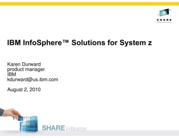
Front ViewModel 6E16514321Diskette drive235Cover release leverMedia bay46Hot-swap disk drives (optional onsome systems)CD-ROM driveOperator panelChapter 1. Introducing the System3
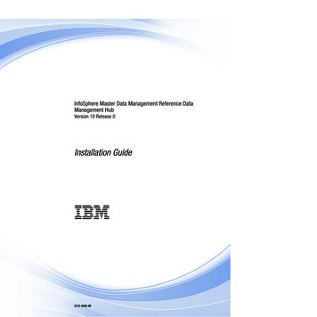
Model 6C134567124User’s Guide1Diskette drive2357Serial port connectorOperator panelCD-ROM drive46Hot-swap disk drives (optional onsome systems)Cover release leverMedia bay
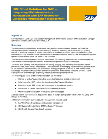
Rear ViewModel 6E1161514131211109876541321PCI slots 1-523PCI slot 364-bit/5VParallel connectorAttention LEDPower LEDSerial connector 1Serial connector 3Mouse connector45791113156810121416PCI slots 1-264-bit/3.3VPCI slots 4-532-bit/3.3VSCSI connectorRack indicator connectorEthernet connector 2Ethernet connector 1Serial connector 2Keyboard connectorChapter 1. Introducing the System5
Model 6C1114 12 1016 15 13 11 9 8 7 61PCI slots 1-523PCI slot 364-bit/5VParallel connectorAttention LEDPower LEDSerial connector 1Serial connector 3Mouse connector45791113156User’s Guide68101214165432PCI slots 1-264-bit/3.3VPCI slots 4-532-bit/3.3VSCSI connectorRack indicator connectorEthernet connector 2Ethernet connector 1Serial connector 2Keyboard connector
Operator Panel123541Power-On Switch2Reset Switch3Display4Attention LED5Power-On LEDChapter 1. Introducing the System7
8User’s Guide
Chapter 2. Using the SystemThis chapter provides information on how to start and use the system.Starting the System Unit1. Set the power switches of the attached devices to On.Note: When the system is plugged in but not powered on, the Power-On LEDflashes slowly.2. If the LED is not flashing and OK is not displayed, ensure that the power cord,located at the back of the system unit, is plugged into a grounded electrical outlet.3. If this does not solve the problem, go to Chapter 8, “Hardware ProblemDetermination” on page 147.4. Press the Power-On switch.When you press the Power-On switch, the Power-On LED comes on, and thesystem starts a POST (power-on self-test).During POST, progress codes display in the operator panel display.5. If the Power-On LED does not come on and there is no indication of power whenyou press the Power-On switch, go to Chapter 8, “Hardware Problem Determination”on page 147.Stopping the System UnitAttention: When you use the shutdown procedure for your system, follow the correctshutdown procedure before you stop the system. Failure to do so can resultin the loss of data. The system is powered down by the shutdownprocedure.1. At a command line, type shutdown to stop the operating system.2. After you shut down the operating system, set the power switches of any attacheddevices to Off.3. If you will be servicing the system, unplug the system-unit power cable from theelectrical outlet.Reading the Operator Panel DisplayThe operator panel display is used to:v Track the progress of the system unit self-tests and configuration programv Display codes when the operating system comes to a
pSeries 610 Model 6C1 and Model 6E