Transcription
GRUNDFOS CIM/CIUCommunication InterfacesCIM/CIUCOMMUNICATIONINTERFACESCOMPLETE CONTROL FOR PUMPS AND PUMP SYSTEMS
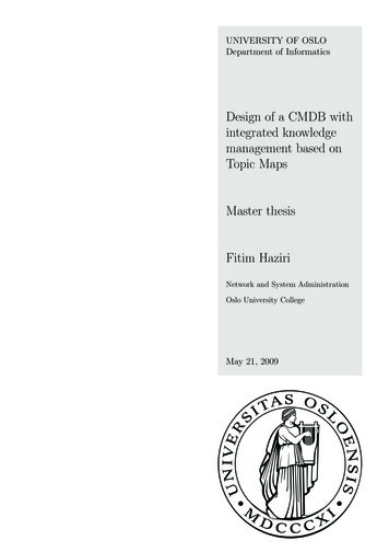
MANAGE YOUR SYSTEMS WITHCIM/CIU COMMUNICATION INTERFACESFor complete control of pump systems, the Grundfos fieldbus conceptis the right solution. The innovative Communication Interface Module(CIM) and the Communication Interface Unit (CIU) enable datacommunication via open and interoperable networks such as Modbus RTUWhy CIM/CIU Connectivity Interfaces? Pumps and controllers have better reliability with reduceddowntime, due to monitoring and control functionality on aBMS/SCADA system The operational cost of pumps can be lowered by reducingsetpoints to match precise system needs via remote control Modbus TCP BACnet MS/TP Remote monitoring and control via BMS/SCADA systems reducemanual settings, monitoring time and travel time to sites orinstallations BACnet IP LONWorks PROFIBUS DP Enable predictive maintenance and fast reaction time on processchanges and exceptions PROFINET IO EtherNet/IP One solution for all products with a modular design prepared forfuture needs Grundfos iSOLUTIONS Cloud/Grundfos Remote ManagementThe series of Grundfos CIM/CIU communication interfaces offer easeof installation and commissioning, user-friendliness and great valuefor money in the long term. All modules are based on standardfunctional profiles for an easy integration into the network and easyunderstanding of data points. One solution offering complete process monitoring and control Flexible wide range power supply 24-240 VAC/VDC (CIU unit) Easy to install and commission, as Grundfos delivers the requiredsupport files and functional profile manualsNetworkCIM modulemounted inCIU unitGENIbusCIM modulemountedin productCIM modulemountedin productDDA withE-box containingCIM moduleAvailable Communication Interfaces CIM 050 for GENIbus CIM 060 for radio communication to Grundfos GO Remote CIM 100/110 for LONWorks networks CIM 150 and E-box 150 for PROFIBUS DP CIM 200 and E-box 200 for Modbus RTU CIM 280 for Grundfos iSOLUTIONS Cloud/GRM CIM 300 for BACnet MS/TP networks2 CIM 500 for PROFINET IO, Modbus TCP, BACnet IP,EtherNet/IP and Grundfos iSOLUTIONS Cloud E-box 500 for PROFINET IO, Modbus TCP, EtherNet/IP,Grundfos iSOLUTIONS Cloud CIU 900 unit for any CIM interface CIU 901 CIU unit with IO board CIU 903 for SQFlex/MGFlex
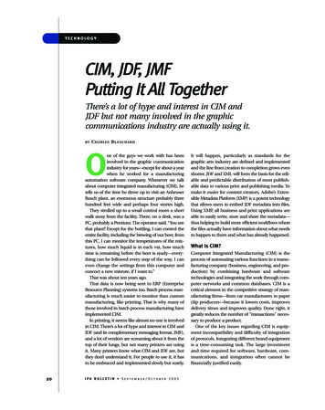
CIM & CIU COMMUNICATION INTERFACES FIELDBUS COMMUNICATIONGrundfos Communication Interface Modules (CIM) and Units (CIU)Creating intelligent communications solutions for applications in Industry, Building Services and Water Utility.Mounting CIM in CIU Unit or E-boxCIMCIU 901(IO 270)CIU 900CIU 903(SQ Flex/MG Flex)E-box(Small DDA)LONCIM 100/110CIU 100/110 assembly--PROFIBUS DPCIM 150CIU 150 assembly-E-box 150Modbus RTUCIM 200CIU 201 assemblyCIU 201 assemblyE-box 200BACnet MS/TPCIM 300CIU 300 assembly--Cellular 3G/4G for GrundfosiSOLUTIONS Cloud/GRMCIM 280CIU 280 assemblyCIU 281 assemblyCIU 283 assembly-Industrial EtherNetCIM 500CIU 500 assemblyCIU 501 assemblyCIU 503 AssemblyGrundfos iSOLUTIONSCloud/GRM onlyE-box 500CIM ModulesCIU 901 Wall-Mounted/DIN-Rail UnitThe CIM is an add-on communication module installed internally.A CIU 900 unit with additional I/O board integrated which contains:Single pumps: 2 configurable inputs (digital or analog 0/4-20 mA, 0-10 V) E-Pumps: All PM & 20-30HP Async 1 Relay output (230 V, 2 A) MAGNA3 circulator pumps 1 Analog signal output (0-10 V)Boosters: 1 Temperature input (Pt100/Pt1000, 2-wire) Hydro/Control MPC, CU 352 2 digital inputs DDD control, CU 354Supported from CIM 200 Modbus RTU, CIM 280 Grundfos iSOLUTIONSCloud/GRM, CIM 500 (Modbus TCP, Grundfos iSOLUTIONS Cloud/GRM) Hydro Multi-E and Hydro Multi-B MAGNA3-D twin circulator pumps TPED twin pump model H/IWastewater controllers: Dedicated Controls, CU 362 Level Control, LC 2x1CIU 900 Wall-Mounted/DIN Rail UnitThe CIU 900 with internal power supply is for Grundfos productsthat do not support the internal mounting of the CIM module. TPED 11-22 kW CUE drive for various standard pumps MP 204 motor protector DDA model XLCIU 903 Wall-Mounted/DIN Rail Unit A CIU 900 unit but with integrated powerline communicationto connect to wastewater MGEFlex and SQFlex pumps. Supported from CIM 280 Grundfos iSOLUTIONS Cloud/GRM,CIM 500 with Grundfos iSOLUTIONS Cloud/GRM only. CIU 903 solution for external 24 V AC/DC power supply(not for solar power).E-BoxAn external communication unit for small DDA dosing pumps. E-box 150 PROFIBUS DP with build in CIM 150 E-box 200 Modbus RTU with build in CIM 200 E-box 500 Ethernet with build in CIM 500 for support of PROFINET,Modbus TCP, EtherNet/IP and Grundfos iSOLUTIONS Cloud/GRM3
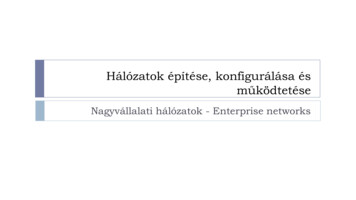
FIELDBUS COMMUNICATIONCIM/CIU Interface Products Mapped To ProtocolsMAGNA3-DTwin pump 2)MAGNA 3GENIbusTPED 11-22 kWTwin pumpTwin pumpTPED ModelH/I 1)E-PumpsAll PM & 20-30HP AsyncCUEbuilt-inbuilt-inbuilt-inbuilt-inHydro MPC(CU 352)Multi-E MGE11-22 kWmodel G/FMulti-EModelH/I/J 1)MP 204built-inbuilt-inbuilt-inCIM 050DedicatedControls(CU 362)LC 2x1DDAdosing 3)built-inCIM 050CIM 050CIM 050CIM 110CIM 1002x CIU 900 2x CIM 100CIM 110CIM 100CIU 900 CIM 100CIM 110CIU 900 CIM 100CIM 110CIM 150CIM 1502x CIU 900 2x CIM 150CIM 150CIM 150CIU 900 CIM 150CIM 150CIU 900 CIM 150CIM 150CIU 900 CIM 150CIM 150CIM 150CIU 900 CIM 150 orE-box 150CIM 500CIM 5002x CIU 900 2x CIM 500CIM 500CIM 500CIU 900 CIM 500CIM 500CIU 900 CIM 500CIM 500CIU 900 CIM 500CIM500CIM500CIU 900 CIM 500 orE-box 500CIM 500CIM 5002x CIU 900 2x CIM 500CIM 500CIM 500CIU 900 CIM 500CIM 500CIU 900 CIM 500CIM 500CIU 900 CIM 500CIM 500CIM 500CIU 900 CIM 500 orE-box 500CIM 200CIM 2002x CIU 900 2x CIM 200CIM 200CIM 200CIU 900 CIM 200CIM 200CIU 900 CIM 200CIM 200CIU 900 CIM 200CIM 200CIM 200CIU 900 CIM 200 orE-box 200CIM 500CIM 5002x CIU 900 2x CIM 500CIM 500CIM 500CIU 900 CIM 500CIM 500CIU 900 CIM 500CIM 500CIM 300CIM 3002x CIU 900 2x CIM 300CIM 300CIM 300CIU 900 CIM 300CIM 300CIU 900 CIM 300CIM 300CIM 500CIM 5002x CIU 900 2x CIM 500CIM 500CIM 500CIU 900 CIM 500CIM 500CIU 900 CIM 500CIM 500CIM 280/CIM 500CIM 280/CIM 5002x CIU 900 2x CIM 280/ 2x CIM 500CIM 280/CIM 500CIM 280/CIM 500CIU 900 CIM 280/CIM 500CIM 280/CIM 500CIU 900 CIM 280/CIM 500CIM 280/CIM OFINET IOModbus TCPModbus RTUEtherNet/IPBACnetMS/TPCIU 900 CIM 500 orE-box 500BACnet IPGrundfosiSOLUTIONSCloud 4)Radio toGrundfosGO RemoteCIU 900 CIM 280/CIM 500CIM 280/CIM 500CIM 280/CIM 500built-inCIM 060Note: To create a CIU xxx solution, you need to order a CIU 900 the required CIM xxx interface and mount the CIM xxx interface into CIU 900. This is the same for a CIU xx1, CIU xx2, CIU xx3.1) A second CIM module can optionally be mounted in pump no. 2 for redundancy2) MAGNA3-D model D requires 1x CIM in master head, MAGNA3-D models A-C require a CIM in each head (for LON 2x CIM 100)3) Small DDA uses the E-box, whereas DDA XL uses the CIU unit plus the appropriate CIM module4) CIM 280 Grundfos iSOLUTIONS Cloud/GRM 3G/4G are available in regional versions for USA (consider needed 3G/4G frequency bands)Note: Hydro Multi-B is supported by CIM 050 GENIbus, CIM 110 LON, CIM 200 Modbus RTU, CIM 300 BACnet MS/TP, CIM 500 (Modbus TCP, BACnet IP),CIM 280 Grundfos iSOLUTIONS Cloud/GRM 3G/4G cellular.Note: E-pumps are CRE/CRNE/CRIE, MTRE, CME, TPE2/TPE3, NBE/NKE.4CIU 900 CIM 500 orE-box 500
PROTOCOLS MAINLY USED IN BUILDING SERVICES FIELDBUS COMMUNICATIONBACnet IP, BACnet MS/TP, LONFor pumps and boostersBACnet IP, BACnet MS/TP, LONMAGNA3E-pumps 11 kWE-pumps model JCUEE-pumps 11-22 kWMulti-E, TPEDHydro MPC/Control MPCHydro Multi-B24-240 VAC/VDC, -10 %/ 15 %0-60 HzMax. 11 WIEC: 0.2-4 mm2, UL: 24-12 AWGIP 54, according to IEC 605296 x M16 Ø4 - Ø10-20 C to 45 C (-4 F to 113 F)-20 C to 60 C (-4 F to 140 F)182 x 108 x 82 mms if sensor installeds* available with sensor or TPE 2000and TPE31 differential or absolute, depends on sensor2Not standard for Control MPCMAGNA/UPEGeneral CIU 900 DataSupply voltageFrequencyPower consumptionCable sizeEnclosure classCable entryOperating temperaturesStorage temperaturesDimensions (H/W/D)Data PointsOperating Mode Setpoint Control Mode H HG only for MGE model G or laterH only for MGE model H or laterControlRelay ControlTank Filling Status StatusGENIbus CommunicationProtocol GENIbusTransceiverRS-485Recommended cable typeScreened, double twisted-pairMaximum cable length1200 m/4000 ftOperating Mode Status Control Mode Status Feedback Alarm/Warning Information G Bearing Service InformationTank Filling Control Measured DataCIM 500 BACnet IP CommunicationProtocol BACnet IP(set rotary switch to position 2)Transmission speeds10/100 Mbit/sPorts 2x RJ45IP settingsbuilt-in webserverPower/Energy Consumption Pressure (Head) s*s* 2sFlow s*s*H s 2Relative Performance Speed and Frequency Digital Input/Output s1Motor CurrentCIM 300 BACnet MS/TP CommunicationProtocolTransceiverTransmission speedsBACnet master addressMotor VoltageBACnet MS/TP (Master)RS-4859.6, 19.2, 38.4, 76.8 kbits/s0-127CIM 100 LON for Pumps/CIM 110 LON for Boosterand Twin Pump CommunicationProtocol LONtalkTransceiverFTT-10Transmission speeds78 kbits/sRemote FlowInlet Pressure 1LevelG only G ssH sG ssH ssG ssH ssH sssssG sssssH s G ssH sBearing TemperaturesH ssAuxilary Sensor InputsMotor TemperatureRemote TemperaturePump Liquid Temperature sH sOperation Time (Run Time) Total On Time VolumeH sCUE sAmbient Temperature H sH sInlet and Outlet TemperaturesHeat Energy MeterTo controller/SCADAsRemote Pressure 1Number Of StartsExample with BACnet MS/TPss ss HOutlet Pressure 1H sH sssFeed Tank LevelH sH sssAlarm/Status Information Operation Time (Run Time) SpeedH Line Current/Power ConsumptionH Motor TemperatureH Number of StartsH Subpump DataControl Pump: Force To Stop/AutoE-pump11-22 kW withCIM 500 built-inMAGNA3with CIM 500built-inHydro MPCwith CIM 500built-inNote 1) E-pumps CRE/CRNE/CRIE, MTRE, CME, TPE2/TPE3, NBE/NKE.Note 2) TPED twin pump model F or G in range 3-22 kW needs always 2 CIU modules.Note 3) MAGNA3-D twinpump model D requires 1x CIM interface installed in master head.For LON 1x CIM 110 installed in master head.5
FIELDBUS COMMUNICATION PROTOCOLS MAINLY USED AT INDUSTRIAL AUTOMATION AND WATER UTILITYPROFINET IO, Modbus TCP, EtherNet/IP, PROFIBUS DP, Modbus RTUFor pumps and boostersGENIbus CommunicationProtocol GENIbusTransceiverRS-485Recommended cable typeScreened, double twisted-pairMaximum cable length1200 m/4000 ftCIM 500 PROFINET IO, Modbus TCP,EtherNet/IP CommunicationProtocolPROFINET IO (rotary switch position 0)Modbus TCP (rotary switch position 1)EtherNet/IP (rotary switch position 3)Transmission speeds10/100 Mbits/sPorts 2x RJ45Conformance classBCIM 200 Modbus RTU CommunicationProtocolTransceiverTransmission speedsParity settingsStop bits.Modbus Slave addressModbus RTURS-4851.2, 2.4, 4.8, 9.6, 19.2, 38.4 kbits/sEven, Odd or No parity1 or 21-247, set via rotary switchesCIM 150 PROFIBUS DP CommunicationProtocolTransceiverImplementation classTransmission speedsSlave addressPROFIBUS DPRS-485DP-V09600 bits/s to 12 Mbit/s1-126, set via rotary switchesExample with CIM 500To controller/SCADASwitchCIU 500GENIbusMP 2046E-pump 11-22 kWwith CIM 500 built-inMAGNA3 withCIM 500 built-inHydro/Control MPCwith CIM 500 built-in H MP 204 Hydro Multi-B Hydro MPC/Control MPCControlOperating ModeSetpointControl ModeRelay ControlTank filling controlStatusOperating Mode StatusControl Mode StatusFeedbackAlarm and warning informationBearing Service informationTank filling status informationMeasured DataPower/Energy ConsumptionPressure (Head) 1FlowRelative PerformanceSpeed and FrequencyDigital Input/OutputMotor CurrentDC Link VoltageMotor VoltageRemote FlowInlet Pressure 1Remote Pressure 1LevelMotor TemperatureRemote TemperaturePump Liquid TemperatureBearing TemperaturesAuxilary Sensor InputOperation Time (Run Time)Total on timeTorque (N/A on 1-phased motors)Number Of StartsMulti-E, TPEDs if sensor installeds* available with sensor orTPE 2000 and TPE31 differential or absolute,depends on sensor2Not standard for Control MPC3Not supported for all pump variantsH only MGE model H or laterG only MGE model G or laterCUEE-pumps 11-22 kWCIU 902 is used together with wastewater AUTOADAPT pumpsCIU 903 is used together with MGEFlex and SQFlex pumps, andonly with CIM 280 for Grundfos iSOLUTIONS CloudPROFINET IO, Modbus TCP, EtherNet/IP, PROFIBUS DP, Modbus RTUE-pumps 11 kWE-pumps model J24-240 VAC/VDC, -10 %/ 15 %0-60 HzMax. 11 WIEC: 0.2-4 mm2, UL: 24-12 AWGIP 54, according to IEC 605296 x M16 Ø4 - Ø10-20 C to 45 C (-4 F to 113 F)-20 C to 60 C (-4 F to 140 F)182 x 108 x 82 mmMAGNA3Supply voltageFrequencyPower consumptionCable sizeEnclosure classCable entryOperating temperaturesStorage temperaturesDimensions (H/W/D)Data PointsMAGNA/UPEGeneral CIU 900, CIU 901, CIU 902, CIU 903 H s*s* G onlyG sG sG ssG ssG sH ss s*s* sssssssss VolumeH sCUE sAmbient TemperatureInlet and Outlet TemperaturesHeat energy meter Outlet Pressure 1Feed Tank LevelPhase VoltagesLine Voltages/Currents/FrequencyStart/Run CapacitorVoltages Angles Cos phiInsulation resistanceStarts/h and auto restarts/24hSubpump Data (for each sub pump in the system)Status informationAlarm informationOperation Time (Run Time)SpeedLine current/power consumptionMotor temperatureNumber of startsControl pump: forc to stop/autoH sH sssHH sH sH sH s 2sss s H s 2 2 s H sH sH sH ssssH ssH s sss ss HHHH Note 1) E-pumps CRE/CRNE/CME, MTRE, CHIE, TPE2/TPE3, NBE/NKE; Note 2) For DDA dosingpumps please view to DDA related pages; Note 3) TPED twin pump model F or G in range 3-22 kWneeds always 2 CIU modules; Note 4) MAGNA3-D twin pump model D only requires 1x CIM interfaceinstalled in master head; Note 5) Hydro Multi-B only supported by Modbus RTU and Modbus TCP
USED FOR COMMUNICATION IN WASTEWATER FIELDBUS COMMUNICATIONPROFINET IO, Modbus TCP, EtherNet/IP, PROFIBUS DP, Modbus RTUFor wastewater productsCIU 902 is used together with wastewater AUTOADAPT pumpsCIU 903 is used together with MGEFlex and SQFlex pumps, andonly with CIM 280 for Grundfos iSOLUTIONS CloudPROFINET IO, Modbus TCP, PROFIBUS DP, Modbus RTUReset alarmGENIbusRS-485Screened, double twisted-pair1200 m/4000 ftCIM 500 PROFINET IO, Modbus TCP, EtherNet/IPCommunicationTransmission speedsPortsConformance class Interlock pit Custom relay control (On/Off/Pulse) Pump ControlPumps On/Off/Auto Pump down Configuration Pit operation mode Active alarms/warnings Status/function of float switches Presence of sensors Pit statusGENIbus CommunicationProtocol Pit ControlSet pit and pumps control levelsProtocolTransceiverRecommended cable typeMaximum cable lengthWastewaterAUTOADAPTCIU xx2*24-240 VAC/VDC, -10 %/ 15 %0-60 HzMax. 11 WIEC: 0.2-4 mm2, UL: 24-12 AWGIP 54, according to IEC 605296 x M16 Ø4 - Ø10-20 C to 45 C (-4 F to 113 F)-20 C to 60 C (-4 F to 140 F)182 x 108 x 82 mmDedicatedControlsCU 362Supply voltageFrequencyPower consumptionCable sizeEnclosure classCable entryOperating temperaturesStorage temperaturesDimensions (H/W/D)Data PointsLC 2x1General CIU 900, CIU 901, CIU 902PROFINET IO (rotary switch position 0)Modbus TCP (rotary switch position 1)EtherNet/IP (rotary switch position 3)10/100 Mbits/s2x RJ45BPit mode (single/multi) Real time clock (read and set) Pit control source (Manual/Auto) Pit and pumps control levels Water level Water level max In/out flowPower/Energy consumption 1Specific energy Volume 1Overflow volume/time/counterOperation time 1 Operation time for simultaneous pumps 1 Mixer average starts per hours 3 x user defined sensor inputs CIM 200 Modbus RTU CommunicationFloat switches ProtocolTransceiverTransmission speedsParity settingsStop bitsModbus Slave addressDigital inputs 8 x I/O logic outputsModbus RTURS-4851.2, 2.4, 4.8, 9.6, 19.2, 38.4 kbits/sEven, Odd or No parity1 or 21-247, set via rotary switches 1Digital Outputs Pump statusPresence of pump Pump enabled/disabled Running/Stopped Active alarms/warnings Auxiliary equipment status CIM 150 PROFIBUS DP CommunicationControl source ProtocolPROFIBUS DPTransceiverRS-485Implementation classDP-V0Transmission speeds9600 bits/s to 12 Mbit/sSlave address 1-126, set via rotary switchesOperation time 1 1Starts counter (total/average) 1 1 Example with CIM 500Latest continuous operation timeMax continuous operation timeTime to service 2 Voltage/frequency Current asymmetry Flow (actual/latest)Current (actual/latest)Power/Power factor/Energy consumptionTo controller/SCADASwitch 3 Motor temperature Insulation Water in oil SpecialHour log (latest 72h of main pit/pump values)Event log (50 latest alarms/warnings w. time stamp)User defined data log (40000 registers)Dedicated Controls(CU 362)WastewaterAUTOADAPT1-4 pumpsLC 2x1 4 Note 1) Available as 3 datapoints for yesterday, today and total. For information related to GrundfosiSOLUTIONS Cloud please contact Grundfos; Note 2) LC 2X1 only has actual current; Note 3) LC 2X1 doesnot measure power factor; Note 4) LC 2X1 only has 40 logs*To create a CIU 152, you order CIU 902 CIM 150. To create a CIU 202, you order CIU 902 CIM 200.To create a CIU 502, you order CIU 902 CIM 5007
FIELDBUS COMMUNICATION USED FOR CLOUD/CELLULAR COMMUNICATIONCellular Data Connection to SCADA or Operation Via SMSFor pumps and boostersGENIbus CommunicationProtocolTransceiverRecommended cable typeMaximum cable lengthGENIbusRS-485Screened, double twisted-pair1200 m/4000 ft3G/4G Cellular CommunicationProtocol3G/4G antennaBatterySIM cardSMSData connection (Modbus TCP)Available as an optionAvailable as an optionTo be supplied by user/installerMulti-E, TPEDHydro MPC/Control MPCHydro Multi-BMP 204s if sensor installedCUEE-pumps 11-22 kWCIU 902 is used together with wastewater AUTOADAPT pumpsCIU 903 is used together with MGEFlex and SQFlex pumps, and onlywith CIM 280 for Grundfos iSOLUTIONS CloudCIM 260 3G/4G CellularE-pumps 11 kWE-pumps model J24-240 VAC/VDC, -10 %/ 15 %0-60 HzMax. 11 WIEC: 0.2-4 mm2, UL: 24-12 AWGIP 54, according to IEC 605296 x M16 Ø4 - Ø10-20 C to 45 C (-4 F to 113 F)-20 C to 45 C (-4 F to 113 F)182 x 108 x 82 mmMAGNA3Supply voltageFrequencyPower consumptionCable sizeEnclosure classCable entryOperating temperaturesStorage temperaturesDimensions (H/W/D)Data PointsMAGNA/UPEGeneral CIU 900, CIU 901, CIU 902, CIU 903Operating Mode Setpoint Control Mode H s* available with sensor or TPE 2000 and TPE31differential or absolute, depends on sensor2Not standard for Control MPC3Not supported for all pump variantsG only for MGE model G and laterH only for MGE model H and laterControlRelay ControlTank filling control StatusOperating Mode status Control Mode status Feedback Alarm/warning information G Bearing Service InformationTank filling status informationRead product status Power/Energy Consumption Pressure (Head) 1 s*s* 2sFlow s*s*H s 2Relative Performance Speed and Frequency Digital Input/Output Motor Current DC Link Voltage Motor VoltageRemote FlowsInlet Pressure 1Read network statusSelf-triggered messagesControlConfigurationCIU 901 I/O board8sLevel E.g. pressure, power, temperatureetc. (depends on product type) Request active alarms/warnings Request I/O signal status E.g. signal level, battery status,cellular status and data statistics. Alarm/warning event messages Heart beat messages Set operating mode (e.g. Start/stop) Set control mode(e.g. constant pressure) Set setpoint Reset alarms Set analog output SMS access control via PIN code Configuration of SMS functions Configuration of cellular connection 2 configurable inputs (digital oranalog 0/4-20 mA, 0-10 V) 1 Relay output (230 V, 2 A) 1 Analog signal output (0-10 V) 1 Temperature input(Pt100/Pt1000, 2-wire) 2 digital inputs Measured DataRemote Pressure 1SMS Features Motor TemperatureRemote TemperaturePump Liquid Temperatures G ssH sG ssH ssG ssH ssH ssH sssssssG ss H ssAuxilary Sensor InputssH sOperation Time (Run Time) Total on time VolumeH sCUE ssAmbient TemperatureH s H sInlet and Outlet TemperaturesHeat energy meterssBearing TemperaturesNumber Of Starts G onlyG s ss HOutlet Pressure 1H sH s 2sFeed Tank LevelH sH sssPhase Voltages Line Voltages/Currents/Frequency Start/Run Capacitor Voltage Angles Cos phi Insulation resistance Starts/h and auto restarts/24h Subpump DataAlarm/Status information Operation Time (Run Time) SpeedH Line current/power consumptionH Motor temperature Number of starts Control pump: force to stop/auto Note 1) E-pumps CRE/CRNE/CRIE, MTRE, CME, TPE2/TPE3, NBE/NKE.Note 2) TPED twin pump model F or G in range 3-22 kW needs always 2 CIU modules.Note 3) MAGNA3-D twinpump model D requires 1x CIM interface installed in master head.
USED FOR CLOUD/CELLULAR COMMUNICATION IN WASTEWATER FIELDBUS COMMUNICATIONCellular Data Connection to SCADA or Operation Via SMSSupply voltageFrequencyPower consumptionCable sizeEnclosure classCable entryOperation temperaturesStorage temperaturesDimensions (H/W/D)CIM 260 3G/4G Cellular *24-240 VAC/VDC, -10 %/ 15 %0-60 HzMax. 11 WIEC: 0.2-4 mm2, UL: 24-12 AWGIP 54, according to IEC 605296 x M16 Ø4 - Ø10-20 C to 45 C (-4 F to 113 F)-20 C to 60 C (-4 F to 140 F)182 x 108 x 82 mmWastewaterAUTOADAPTCIU 262Data PointsDedicatedControlsCU 362General CIU 900, CIU 901, CIU 902, CIU 903LC 2x1For pumps and boosters Pit ControlReset alarmInterlock pit Custom relay control (On/Off/Pulse) Pump ControlCIU 902 is used together with wastewater AUTOADAPT pumpsCIU 903 is used together with MGEFlex and SQFlex pumps, andonly with CIM 280 for Grundfos iSOLUTIONS CloudPumps On/Off/Auto Pump down ConfigurationSet pit and pumps control levels Pit statusGENIbus CommunicationProtocolTransceiverRecommended cable typeMaximum cable lengthGENIbusRS-485Screened, double twisted-pair1200 m/4000 ftCellular CommunicationProtocol3G/4G antennaBatterySIM cardRead network statusSelf-triggered messagesControlConfigurationI/O board Status/function of float switches Presence of sensors Pit control source (Manual/Auto) Pit and pumps control levels Water level Pit mode (single/multi) Real time clock (read and set) Water level maxSMSCellular data connection (Modbus TCP)Available as an optionAvailable as an optionTo be supplied by user/installerSMS FeaturesRead product statusPit operation modeActive alarms/warnings E.g. pressure, power, temperatureetc. (depends on product type) Request active alarms/warnings Request I/O signal status E.g. signal level, battery status,cellular status and data statistics. Alarm/warning event messages Heart beat messages Pit interlocking Reset alarms SMS access control via PIN code Configuration of SMS functions Configuration of cellular connection 2 configurable inputs(digital or analog 0/4-20 mA, 0-10 V) 1 Relay output (230 V, 2 A) 1 Analog signal output (0-10 V) 1 Temperature input (Pt100/ Pt1000 , 2-wire) 2 digital inputs In/out flowPower/Energy consumption 1Specific energy Volume 1Overflow volume/time/counter 1Operation time 1 Operation time for simultaneous pumps 1 Mixer average starts per hours 3 x user defined sensor inputs Float switches Digital inputs 8 x I/O logic outputsDigital Outputs Pump statusPresence of pump Pump enabled/disabled Running/Stopped Active alarms/warnings Control source Operation time 1 1Starts counter (total/average) 1 1 Auxiliary equipment status Latest continuous operation timeMax continuous operation timeTime to service Flow (actual/latest)Current (actual/latest) 2 Voltage/frequency Current asymmetry Power/Power factor/Energy consumption 3 Motor temperature Insulation Water in oil SpecialHour log (latest 72h of main pit/pump values)Event log (50 latest alarms/warnings w. time stamp)User defined data log (40000 registers) 4 Note 1) Available as 3 datapoints for yesterday, today and total. For information related to ModbusTCP, PROFINET or Grundfos iSOLUTIONS Cloud please contact Grundfos. Note 2) LC 2X1 only hasactual current Note 3) LC 2X1 does not measure power factor Note 4) LC 2X1 only has 40 logs* To create a CIU 262, you order a CIU 902 CIM 2609
FIELDBUS COMMUNICATION PROTOCOLS MAINLY USED AT DOSING APPLICATIONSDDA E-Box VersionFor Grundfos digital dosing pumpsThe small DDA is mounted directly on top of the E-box, and the buscable included with the E-box is connected between the small DDAand E-box. The DDA XL uses the CIU unit solution, and the GENIbuscable is ordered separately.DataPointsDDA E-box 150, E-box 200 or E-box 500Control variant - AROperating Mode (Start, Stop, Service, Calibrating),Functions (Slowmode, Viscosity selection), Deaerating mode Function Enable/Disable (AutoDearating, FlowMonitor, ProfibusWatchdog, AutoFlow, PulseMemory) Pulse signal from bus Reset Fault and Volume Counter Control Mode (Manual, Pulse, Analogue, Timer, Batch) Set Manual Flow Setpoint Set Pulse Volume Set Batch Volume Set Batch Dosing Time Set Flow Monitor Pressure Alarm Limit Relay Control of Relay 1 and 2 Set Analog Output Set Date & Time Operating Mode Status Control Mode Status Alarm/warning/dosing (running) Status Actual Manual Flow Setpoint Actual Pulse Volume Setting Actual Batch Dosing Volume Setting Actual Batch Dosing Time Setting Actual Flow Monitor Pressure Alarm Limit Setting Control Source ( HMI, External, Bus) Fault & Warning Code Warning Status Bits Actual Date & Time Max Dosing Pressure Max Dosing Capacity Resulting Dosing Capacity Setpoint Remaining Dosing Volume Total Dosed Volume Volume Trip Counter Actual Analog Output Signal Digital Outputs Number Of Starts Run Time Total On Time Stroke Counter Time To Next Dosing Digital Inputs Analog Input Signal Pulse Input Frequency Measured Dosing Capacity Measured Dosing Pressure PROFIBUS DPDP-V09600 bits/s to 12 Mbits/s1-126, set via DDA displayControlModbus RTU Communication (E-box 200)ProtocolTransceiverTransmission speedsParity settingsStop bitsSlave addressControl variant - FCProtocolImplementation ClassTransmission speedsSlave addressControl variant - FCMPROFIBUS -DP Communication (E-box 150)Modbus RTURS-4851.2, 2.4, 4.8, 9.6, 19.2, 38.4 kbits/sEven, Odd or No parity1 or 21-247, set via DDA displayCIM 500 PROFINET IO, Modbus TCP, EtherNet/IPCommunicationProtocolPROFINET IO (rotary switch position 0)Modbus TCP (rotary switch position 1)EtherNet/IP (rotary switch position 3)Transmission speed10/100 Mbits/sPorts2 x RJ45PROFINET conformance classBNetwork Example withCIM 500 EthernetTo controller/SCADASwitchCIU unit withCIM moduleGENIbusStatusMeasured DataSmall DDAwith E-box10DDA XLwith CIU
PRODUCT NUMBERSProduct Numbers of Grundfos CIM/CIU Communication InterfacesFor pumps and boostersInterface NameProduct No.CommentCIM 040 GENI TTL98415941For CU 354 DDDCIM 050 GENIbus96824631CIM 060 GlowPan98778356Require 98778357 Antenna kit for CIM 060CIM 100 LON96824797LON for pumpsCIM 11096824798LON for boosters and twin pumps. Install CIM in master head intwin pumps and Multi-ECIM 150 PROFIBUS DP96824793E-box 150 PROFIBUS DP97513994CIM 200 Modbus RTU96824796E-box 200 Modbus RTU98563350For small DDA pumpsCIM 260-EU 3G/4G cellular99439302For European frequency bands. Requires 99518079 antenna kit.3G/4G SIM cardCIM 260-US 3G/4G cellular99439306For North America frequency bands. Requires 99518079 antenna kit.3G/4G SIM cardCIM 280-EU Grundfos iSOLUTIONS Cloud/GRM 3G/4G 1)99439724For European frequency bands. Requires 99518079 antenna kit. 3G/4GSIM card must have additional international PDU SMS roaming active.CIM 280-US Grundfos iSOLUTIONS Cloud/GRM 3G/4G 1)99439725For North America frequency bands. Requires 99518079 antenna kit. 3G/4GSIM card must have additional international PDU SMS roaming active.CIM 300 BACnet MS/TP96893770CIM 500 Ethernet 1)98301408For Industrial Ethernet protocols PROFINET, Modbus TCP, BACnet IP,EtherNet/IP and for GRM IPE-box 500 Ethernet 1)99171932For Industrial Ethernet protocols PROFINET, Modbus TCP, EtherNet/IPand for GRM IP for small DDA pumpsCIU 90099448387Empty CIU unit. For all CIM modulesCIU 90199448389Empty CIU unit with built-in IO board (IO 270).For CIM 200, CIM 260 and CIM 500CIU 902 AUTOADAPT97644690Empty CIU unit with built-in SEG AUTOADAPT board for interface to 1-4SEG AUTOADAPT pumps. For CIM 150, CIM 200, CIM 260 and CIM 500.CIU 903 MGEFlex/SQFlex98106399Empty CIU unit with interface for MGE Flex and SQ Flex.Only used for CIM 280.CIM 060 antenna kit98778357Antenna required only in case of no sight viewCIM 260/280 puc antenna kit (1.5 m cable)99518079CIM 260/280 optional battery99499908CIM500 RJ45 Field plugs kit98471752DDA GENIbus cable (3 m)98589048For connection to CIU unitRobustel R3000-L3H, 3G router99043055For use with CIM 500Robustel R3000-L4L, 4G router99043057For use with CIM 5003G/4G rod antenna for Robustel Router (5 m cable)99043061External power supply 12 V for Robustel Router99043052For small DDA pumpsNote: To create a CIU xxx version you need to order a CIU 900 CIM xxx interface, similar for a CIU xx1 or CIU xx2 or CIU xx31) Additional GRM contract needed for data hosting in Grundfos iSOLUTIONS Cloud/GRM11
LCISL001 0320As a pioneer and global leader in water pump technology, Grundfos createsintelligent, sustainable solutions to help solve the world’s water and climatechallenges. Through our heritage, we have the experience and innovative capabilitiesto help our partners, customers and communities move water in an increasinglyenergy and water efficient manner. We see this as not only a great busin
is the right solution. The innovative Communication Interface Module (CIM) and the Communication Interface Unit (CIU) enable data . Remote monitoring and control via BMS/SCADA systems reduce manual settings, monitoring time and travel time to sites or . (digital or analog 0/4-20 mA, 0-10 V) 1 Relay output (230 V, 2 A)