Transcription
Electric Drivesand ControlsHydraulicsLinear Motion andAssembly TechnologiesPneumaticsMP18 Stacking Valve SystemTechnical Information ManualThe Drive & Control CompanyService
MP18 STACKING HYDRAULIC VALVE MANUALCopyright 1996 Bosch Rexroth Canada Corp.All rights reserved.Reproduction or use of editorial or pictorial content in any manner is prohibited without the express permissionof:Bosch Rexroth Canada Corp.While every precaution has been taken in the preparation of this manual, the publisher assumes noresponsibility for errors or omissions. Neither is any liability assumed for damages resulting in the misuse of theprinted material contained herein.First Edition 1996Revised Edition 2006Printed in Canada for:Bosch Rexroth Canada Corp.3426 Mainway DriveBurlington, OntarioCanadaL7M 1A8Phone: (905) 335-5511Fax:(905) 335-8959Toll Free: 1-877-266-78111-877-COMPU-11Bosch Rexroth Canada Corp. 3426 Mainway Drive Burlington, Ontario, Canada L7M 1A8 www.boschrexroth.caPage 1 of 266/16/2006
MP18 STACKING HYDRAULIC VALVE MANUALTABLE OF CONTENTSTABLE OF CONTENTS . 2FEATURES . 3FUNCTIONAL PURPOSE. 3DESCRIPTION. 4SPECIFICATIONS . 5Pressure. 5Flow. 5Solenoids . 5Number of Sections . 5OPERATING CONDITIONS. 6Recommended Filtration. 6PRESSURE ADJUSTMENTS . 6Open Centre Unloading Inlet . 6PRESSURE ADJUSTMENTS . 7A and B Port Reliefs. 7FIELD CONVERSIONS. 8Open Centre Unloading Inlet with Power Beyond Port. 8UNIT DIMENSIONS . 9Standard Port Sizes (SAE) . 9Closed Centre Inlet with Standard End Cover . 10Open Centre Inlet with Standard End Cover . 10HIGHBOY/LOWBOY MANIFOLD SECTIONS. 11SPINNER AND AUGER/CONVEYOR ASSEMBLIES ONLY . 12BUILDING A MANIFOLD BANK ASSEMBLY . 13What you need to build a valve assembly . 13BUILDING A MANIFOLD BANK ASSEMBLY . 14Recommended Assembly Order. 14PROBLEM SOLVING GUIDE . 15STANDARD SPARE PARTS . 17Standard Inlet Sections. 18Secondary Port Options. 19Primary Shuttle Assembly. 20Secondary Shuttle Assembly . 20Flow Controls and Compensators. 21Directional Valve Spools . 22Section End Caps . 23Solenoid Assembly . 23O-Rings . 23Mechanical Accessories . 24Pilot Options. 24Detent Assemblies . 24Standard End Covers . 25Bosch Rexroth Canada Corp. 3426 Mainway Drive Burlington, Ontario, Canada L7M 1A8 www.boschrexroth.caPage 2 of 266/16/2006
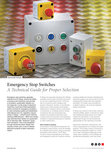
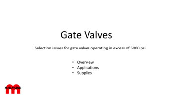
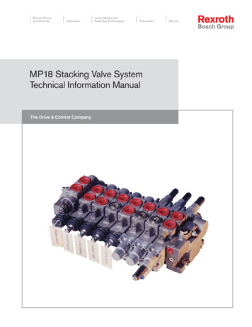
MP18 STACKING HYDRAULIC VALVE MANUALFEATURES Modular (stacked) Design for Custom ApplicationOpen and Closed Centre Inlets are Available (for use with fixed or variable displacement pumps)Pressure Control is Built inFlow Control is Independent of LoadSections Operate Independently of Each OtherConveyor Reverse Function AvailableLoad Checks are Built InManual Overrides are IncorporatedLong Service LifeSmall SizeCast Iron ConstructionFUNCTIONAL PURPOSEThis stacking section type valve system provides modular building blocks for constructing hydraulic circuits tomeet the needs of any spreader truck application.Inlet sections are available to accept the flow from variable (piston) or from fixed (gear) pumps in an energyefficient manner.Valve spool sections allow for electronic control of the spreader hydraulic motors, in forward or in reverse. In thisway, the operator can vary the spinner speed and the Compu-spread electronic controller can automatically varythe material conveyor/auger speed, according to the vehicle speed, maintaining a selectable and constantspread rate. An optional material conveyor/auger reverse function is also available for use in solving theproblem of conveyor/auger jamming caused by ice or foreign material (ie: rocks or bricks).The valve circuit is extendable to control the other hydraulic actuators on your truck (such as: plow functions anddump hoists) simply by adding valve sections. Any of these additional valve sections can also be electronicallycontrolled or they may be operated by on/off electrical solenoids, proportional air pilots, mechanical cables orlevers, the choice is yours. You may also choose to add mechanical detents and/or port relief valves with makeup checks to any of these additional valve sections.Modular stacking valve spool sectionBosch Rexroth Canada Corp. 3426 Mainway Drive Burlington, Ontario, Canada L7M 1A8 www.boschrexroth.caPage 3 of 266/16/2006
MP18 STACKING HYDRAULIC VALVE MANUALDESCRIPTIONIndividual manifold sections, containing the integrated circuit valving for each specific hydraulic function (such asthe conveyor/auger motor drive), are bolted together to form a system specifically suited to your particularvehicle.A closed centre inlet section is incorporated for use with variable displacement (piston) pumps. This inlet has aload (pressure) sensing port for communicating the system’s requirements to the pump’s control valves. In thisway the pump will limit the maximum pressure that can be produced and will only provide the power that yourhydraulic system requires.If a fixed displacement pump is to be used, an open centre inlet section is selected. This inlet has a relief valveincluded, to limit the maximum pressure that can be produced. The relief valve also provides a load (pressure)sensing control based on the system’s requirements. In this way the excess flow, provided by the pump, isbypassed to the reservoir at no greater pressure than necessary, reducing the power wasted (heat) that occursin fixed displacement pump systems.A load (pressure) sensing circuit within the valve sections determines the maximum pressure requirement ofyour vehicle and communicates this information to the main pressure control valve. This main pressure controlvalve could be in the pump (variable displacement types) or in the inlet section of this valve assembly, if a fixeddisplacement pump is used.The spreader valve sections have main spools that are positioned by electronic solenoids, to control the oil flowto, and therefore speed of, the hydraulic motors. The flow is controlled proportionally to the electric currentsupplied. An optional electronic solenoid is available to operate the material conveyor/auger in reverse. Thisoption is useful if the material conveyor/auger should become jammed by some foreign object. Any additionalvalve sections (ie: for plow functions) can also be electronically controlled or they may be operated by on/offelectrical solenoids, proportional air pilots and mechanical cables or levers, the choice is yours.Each valve section contains a pressure control valve that monitors the load (pressure) requirement of itshydraulic actuator and provides constant fluid flow (compensates) regardless of load changes andregardless of other valve section activity. By doing this, control is consistent and repeatable.Manual overrides are provided for emergency operation of the valves should the electronic controller fail and toaid in trouble shooting the system. There is an override pin in the end of each electrical solenoid. The harder thepin is pushed the faster the hydraulic motor should turn. There is also an override screw at the end of the mainvalve spools. By turning these screws in, you can position the spools to establish a desired hydraulic motorspeed. See the spare parts illustration of the end caps.This modular arrangement allows an addition of auxiliary sections for plow and wing functions etc. For furtherassistance when specifying additional valve sections please consult your nearest Bosch Rexroth Canada Corp.Bosch Rexroth Canada Corp. 3426 Mainway Drive Burlington, Ontario, Canada L7M 1A8 www.boschrexroth.caPage 4 of 266/16/2006
MP18 STACKING HYDRAULIC VALVE MANUALSPECIFICATIONSPressureMaximum Primary Relief Setting 3,000 P.S.I.FlowMaximum Flow 35 G.P.M. (133L/Min.)SolenoidsOn/OffType of SupplyNominal Voltage (V)Power Requirement @ 65oF20oC(W)Coil Resistance (ohms)Duty in (%)ProportionalType of SupplyNominal Voltage (V)Power Requirement @ 65oF20oC (W)Coil Resistance (ohms)Duty in (%)Number of SectionsP/N 029636 12 VoltP/N 029752 24 VoltDC12DC2414.41010014.440100P/N 138956 12 VoltP/N 202707 24 VoltDC12DC241.82.41000.8121008 sections maximumNote: Please consult Bosch Rexroth when ordering 8 or more sectionsBosch Rexroth Canada Corp. 3426 Mainway Drive Burlington, Ontario, Canada L7M 1A8 www.boschrexroth.caPage 5 of 266/16/2006
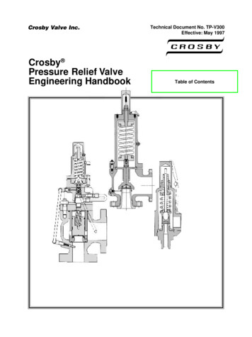
MP18 STACKING HYDRAULIC VALVE MANUALOPERATING CONDITIONSRecommended FiltrationIn order to guarantee reliable function, both return and pressure filters should have 10 micron absolute elementsinstalled.PRESSURE ADJUSTMENTSOpen Centre Unloading InletTurn the maximum pressure adjustment screw (as shown) counter clockwise as far as possible. To do this youmust first l
speed. See the spare parts illustration of the end caps. This modular arrangement allows an addition of auxiliary sections for plow and wing functions etc. For further assistance when specifying additional valve sections please consult your nearest Bosch Rexroth Canada Corp.