Transcription
1FIFO:1-clock FIFOand2-clock FIFO
2ProducerProducerConsumer1-location BufferProducerConsumerConsumerFIFO
3A water tank delinks thepumping of water bythe city andconsumption of waterby the residents.In the same fashion aFIFO delinks theproducer of data andthe consumer of data byholding the excessiveproduction in the FIFO.
4FIFODelinks the producer and theconsumerPRODUCERCONSUMER Writer Reader Deposits Data into the FIFO. Reads Data from the FIFO.
5Data lock)Data FlowMatched flow schedules require no lock)HoldingTankCapacitor on circuit boardsUnmatched flow schedules require buffering
6Connecting data withdifferent bit-widths is liketrying to drink water froma fire hose.We need an adapter.FIFOs with “aspect ratio”are used to go from, say, a32-bit data producer to an8-bit data consumer. Here,we are covering FIFOswith same size data.
7Let us use an 8-location FIFO for our design example76PRODUCERCONSUMER54321WPRP0Initially TheFIFO has two pointers to denote the locations to write and read: Write Pointer (WP): The location pointed to by the WP is where producer deposits data. Read Pointer (RP): The location pointed to by the RP is from where consumer reads data. Initially theFIFO is empty. Both WP and RP point to location 0 of the FIFO.
876PRODUCER5CONSUMER4321WP0RPSay the producer starts depositing the data.
976PRODUCERCONSUMER5432WP10FILLEDRP
1076PRODUCERCONSUMER543WP21FILLED0FILLEDRP
1176PRODUCERCONSUMER54WP32FILLED1FILLED0FILLEDRP
EDRP
D0FILLEDRPNow if the reader starts reading from this cycle.
14Points to the locationto be FILLED0RPPoints to the locationto be read
1576WPPRODUCERCONSUMER54FILLED3FILLED2FILLED10RP
ERRP
NSUMERRP10Now if we write to location 7, should theWP be incremented and be allowed topoint to location 0?
18FIFO ( a Circular Buffer)6RP5740312WPDepth (i.e. # of filled locations) WP - RP
19Computing Depth (# of filled locations) Depth (WP – RP) mod 8FIFO Initially EmptyD WP-RP 0-0 0FIFO Depth 4D WP-RP 4-0 0WP6565747403031RP21265RPWPFIFO Depth 1D WP-RP 4-3 16WP5FIFO Depth 7D WP-RP (2-3)mod 8 7747403031212RPRPWP
20Initially EmptyFIFO FullFIFO depth 0D WP-RP 0-0 0FIFO Depth 8ButD WP-RP (3-3)mod 8 065740RP65740331212WPRPWPEMPTY (if most recently it was almost empty)WP – RP 0FULL (if most recently it was almost full)Example Thresholds for Almost Empty and Almost Full: Almost Empty if depth is less than or equal to 2 Almost Full if depth is greater than or equal to 6We need a flip-flop to record whether most recently it was running almost empty or almost full.Otherwise, when WP RP you can’t tellif the FIFO is Empty or Full!!
21FOR AN 8-LOCATION FIFO:POSSIBLE DEPTH VALUES ARE 9 (NOT 8):0, 1, 2, 3, 4, 5, 6, 7, 8BUT WP – RP MOD 8 EXPRESSION YIELDS ONLY 8 VALUES0, 1, 2, 3, 4, 5, 6, 7EMPTY(If it was seen runningalmost empty most recently)FULL(If it was seen runningalmost full most recently)
22MOD SUBTRACTORHow do we design a MOD Subtractor?We are all taught in our elementaryschool how to do subtraction but doyou think subtracters are built usingthat very technique?What is a posted-borrow subtraction?
23MOD SUBTRACTOREXERCISEA digital SUBTRACTOR uses aPOSTED BORROW Technique93910 10 104 0 0 2-12 3 42 7 6 8SUMMARYAn ordinary n-bit subtractor withits borrow output ignored is aMod-2n subtractor.10 10-0-1-1 -1104 0 0 2-12 3 42 7 6 810 10 10-1-1 -1 -1 104 0 0 2-72 3 46 7 6 8
24MOD SUBTRACTORSOLUTIONA digital SUBTRACTOR uses aPOSTED BORROW Technique93910 10 104 0 0 2-12 3 42 7 6 8SUMMARYAn ordinary n-bit subtractor withit’s borrow output ignored is aMod-2n subtractor.10 10-0-1-1 -1104 0 0 2-12 3 42 7 6 810 10 10-1-1 -1 -1 104 0 0 2-72 3 46 7 6 8
25FIFO is like a queue:Next Empty Slotin the queue.(Tail of the queue)Similar to WPSenior-most person inthe queue(Head of the larto RPRP
26FIFO PIN-OUTWENWrite Enable (from the Producer)RENRead Enable (from the Consumer)FULLFull status info (to the Producer)EMPTYEmpty status (to the Consumer)RD (READ DATA)WD (WRITE DATA)FIFOAF (ALMOST FULL)AE (ALMOST EMPTY)AE status info (to the Consumer)(Optional)AF status info (to the Producer)(Optional)CLK
27Since the WP and RP are part of the FIFO, the FIFO PIN-OUT does not change if wechange the FIFO depth from 8 locations to 8K locations!WENWrite Enable (from the Producer)RENRead Enable (from the Consumer)FULLFull status info (to the Producer)EMPTYEmpty status (to the Consumer)RD (READ DATA)WD (WRITE DATA)FIFOWPRPAF (ALMOST FULL)AE (ALMOST EMPTY)AE status info (to the Consumer)(Optional)AF status info (to the Producer)(Optional)CLK
28DETAILED DESIGN OF ASINGLE-CLOCK 8X4 FIFOWe illustrate a detailed design using schematic components .We use here-- an 8x4 register array for the FIFO storage,-- two 3-bit counters for the WP and RP pointers, and-- a 3-bit subtractor.
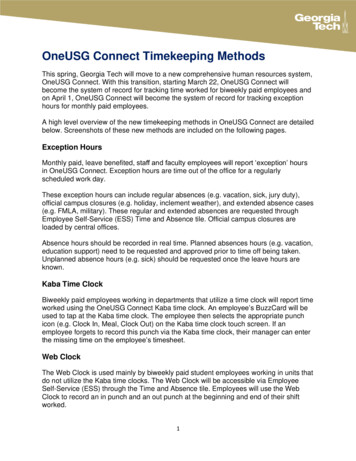
Synchronous FIFO (Common clock for WRITE & A2RA2RA2WA1RA1RA1WA0RA0RA0WENWA0WD3CLKWD2CLR WD1RESET ENQRA2RA1RA0RD3ENQAQBEQCCLK CLKRD2CLR RD1RESET RD0WD[3:0]RD[3:0]RA[2:0]CLKKQ CLR RESET A[2:0]C3RAFFULLDIFF2DIFF1DIFF2DIFF1DIFFRAFRAE
30FIFO StorageRegister Array acting as a Dual Port Memory(a write-only (WO) port and a read-only (RO) port)RAWAWA2WA2WA1WA0RA2WA1DUAL PORT DWD38x4RD3WD2RD2WD1RD1WD0RD0CLKRENQRD3RD2RD1RD0RD
31WP and RP pointers – when toincrement RA2WA1RA1WA0RA0ENQAQBEQCCLK CLKCLKCLR CLR RESET RESET
32Computing DepthA ripple carry adder turned into a subtractorX-YWA2WA1WA0-RA2 RA1X Y’ 1RA0RPRA[2:0]WPVddDIFF[2:0]C0B0B1B2S2S1S0C3Ignore this Borrow as we are building aMod-8 subtractorA1A0A2WA[2:0]DIFF
33RAF and RAEDIFF 11X 110 or 111Raw Almost FullDIFF 01X 010 or 011 Raw Almost EmptyNotice that “000” is excluded from activatingRAF or RAE, as DIFF 000 is the ambiguoussituation that we are trying to disambiguate.
34 We need to record (register) the RAF and RAE to formregistered AF and registered AE. AF Almost Full MRSAF Most Recently Seen the FIFO running Almost FullAE Almost Empty MRSAE Most Recently Seen the FIFO running Almost Empty We need a 2-state state machine, which can be implementedusing either one FF (using the encoded state assignmentmethod) or two FFs (using the one-hot coded stateassignment method).
35R bar
36By using a JK FF and the encoded state assignment method,we can arrive at the NSL heuristically. It’s very simple.Just connect RAF to J and RAE to K.Can haveglitchesGlitches in RAF andRAE die down by theend of the clockCLKRaw Almost FullRaw Almost EmptyRAFRAEJQAFAlmost FullCLKKRESET Q AEAlmost EmptyRegistered valuesremain “as is”when WP RP
37N-bit pointersvs(N 1)-bit pointers
38Another method [called the (n 1)-bit method] to remove(instead of solving) the ambiguity caused by WP-RP 0 Insteadof remembering whether most recently the depth waslingering around the almost empty threshold or the almost fullthreshold, in order to disambiguate the ambiguous situation caused byWP-RP 0, we can avoid the ambiguous situation totally as follows. Forthe 8-location FIFO, we used 3-bit pointers for the WP and the RP.And the 3-bit subtraction (WP-RP)mod 8 produced an 8-valued result[0, 1, 2, 3, 4, 5, 6, 7], where as the depth has nine values, namely [0, 1,2, 3, 4, 5, 6, 7, 8]. This led to the ambiguous situation. Nowsuppose we deliberately use a 4-bit pointer for the WP and a 4-bitpointer for the RP. Then the 4-bit subtraction (WP-RP)mod 16, whichcan potentially produce 16 values (0-15), will produce all the 9 legalvalues (0-8) and will never produce the 7 illegal values (9 through 15).There is no ambiguity to be resolved now!
39Mod 16 or Mod 8 for the 8-location FIFO? To understand the need to do mod 16 subtraction, consider aslow producer and a fast consumer. The consumer would wait forthe producer to deposit one item and he would consume it in thevery next clock. So, the WP would be one step ahead of the RPfor just one clock. Most of the time the WP is equal to the RP. Afew examples are given below.WP 1; RP 0; WP-RP 1 - 0 1;WP 1; RP 1; WP-RP 1 - 1 0;WP 5; RP 4; WP-RP 5 - 4 1;WP 5; RP 5; WP-RP 5 - 5 0;WP 8; RP 7; WP-RP 8 - 7 1;WP 8; RP 8; WP-RP 8 - 8 0;WP 13; RP 12; WP-RP 13 - 12 1; WP 15; RP 14; WP-RP 15 - 14 1;WP 13; RP 13; WP-RP 13 - 13 0; WP 15; RP 15; WP-RP 15 - 15 0;WP 0; RP 15; WP-RP 0 – 15 mod16 1;WP 0; RP 0; WP-RP 0 - 0 0;Note! Hence, we need to perform mod 16.
40WEN Write EnableREN Read EnableFULLEMPTYRENQWENWENQWENQ Write Enable Qualified(Qualified by FULL 0)RENRENQ Read Enable Qualified(Qualified by EMPTY 0)It looks like we the FIFO-designers, do not have faith in the producerdesigner and the consumer designer.We provided the producer the FULL information. So, when he says "write" (byactivating WEN), he must have checked to see that we are not running FULL.Similarly, since we provided EMPTY information to the consumer designer,a responsible consumer designer would have checked to see that we are notrunning EMPTY before he tells us to "read" (by activating REN).If so, why are we double-checking Full and EMPTY as shown above beforeactivating WENQ and RENQ?
41So, should we require thatthe producer requests to write (makes WEN 1)only after ascertaining that FIFO is not full(FULL 0)?And similarly, should we require thatthe consumer requests to read (makes REN 1)only after ascertaining that the FIFO is not empty(EMPTY 0)?YES and NO!!
42YES and NOCRITICAL PATHAt the beginning of a clock, DIFF is produced,and FULL & EMPTY are updated by the FIFO.This info is to be relayed to the PRODUCERand CONSUMER who will then activate WENand REN. Let us try to avoid this round trip.Because if FIFO is FULL it should not be written.And if FIFO is EMPTY it should not be read.Because we can do better in Timing Design.Suggestion for a better timing outcomeThe producer sends a request to write (WEN 1) if he hassomething to write without waiting to check to see ifFULL 1. Later in the clock if he finds that FULL is true,he will RETRY to write the same data again.
Avoiding LONG critical path (round-trip) by breaking it into two one-way tripsLONG round TripEXERCISEPRODUCERCONSUMERFIFOI have an item to consumeI have an item to depositWENRENFULLEMPTYTwo one-way SHORT TripsPRODUCERCONSUMERFIFOI have an item to depositI have an item to consumeWENRENFULLEMPTY43
Avoiding LONG critical path (round-trip) by breaking it into two one-way tripsLONG round TripSOLUTIONPRODUCERCONSUMERFIFOI have an item to consumeI have an item to depositWENRENFULLEMPTYTwo one-way SHORT TripsPRODUCERCONSUMERFIFOI have an item to depositI have an item to consumeWENRENWENQRENQRETRYRETRYFULLEMPTY44
45CDC (Clock Domain Crossing) ClockDomain Crossing (CDC) is a very common situation every digital designerencounters. Ona mother board of a computer, you can easily find 4 to 10 different subsystemsworking on different clocks. Example: A processor may be working at 3 GHz, DDR4 at1GHz, EPROM at 400MHz and the PCI Bus may be working at 66MHz etc. TheRobust method of CDC is to use a 2-clock FIFO.
46WCLK(Write Clock)2-clockFIFOEMPTYRead ClockDomainWrite ClockDomainFULLFIFO is used to bridge theseparately clockeddomainsAn asynchronous FIFO A two-Clock FIFORCLK(Read Clock)
47Depth Calculation for 2-clock FIFOWe just can’t do (WP-RP)mod FIFO Depth to generate depth value as theyare generated in different clock domains. Also, we can’t say when(even for a short moment) the WP and RP values are stable and validtogether.RPWPRPSWPSWPSSRPSSDepth WP - RPSSDepth WPSS - RPDELAY: Safe or Unsafe?
48Never ever try to synchronize a multibit data itemwhen you are crossing a clock domainPWCLKBAD IDEA!!BinaryCountern-bitCdataSyncRegisterRCLKSay WP is changingWPWPSCan potentially be any value from 0(000) to 7 (111) due to metastabilityof the flip-flop.From:011To:100
49For SEQUENTIALLY changing data such as WP and RP useGRAY CODEGRAY CODE:GrayCounterWPWPS01Since only 1-bit changes at most in WP, the WPSS willeither be the old WP or the new WP and will neverbe an absurd value!001110011010
50SYNCHRONIZATION using GRAY CODERPWPRPSWPSWPSSDepth WP - RPSSEXERCISE:Try to write asimilarparagraphfor a fasterwriter.RPSSDepth WPSS - RPDELAY: Safe or Unsafe? Safe!!Say the consumer is faster and the FIFO is running empty for a long time.Now the WRITER just wrote a data itemThe incremented WP takes 1 or 2 clocks to reach the Read Clock domain anduntil that time the reader continues to believe that the FIFO is still empty.So, he will delay consuming the data and this is safe! As long as theconsumer does not consume from an empty FIFO, it is safe!
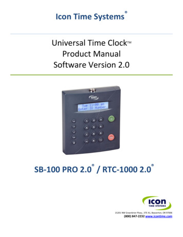
51The (n 1)-bit pointer method for the 2-clock FIFOOn the next slide, we have an 8-location 2-clock FIFO withtwo 4-bit gray-code counters (WP G and RP G), two 4-bitbinary counters (WP Bin and RP Bin), and two depthproducing 4-bit subtractors (one in each of the two clockdomains).Note: The depth inferred in the write-clock domain (depth wr)and the depth inferred in the read-clock domain (depth rd) candiffer substantially tentatively because of the lag in pointerexchange, but it is all on safe side!
WDWP Bin[2:0]3BWCLK4-bit Bin SubtractorA-BWP8-locationRegister ArrayWENQRDdepth rd 0000RPWCLKWP Gray4WP Gray S4RCLKWP Gray SS4RCLKWP SS Bin4RCLK4RP Gray SS4RP Gray S4WCLKRP Gray4WCLKGrayCounterRENQRP SS BinEMPTYRENQWENQGrayCounterWP Bin[3:0]43Gray toBinaryCounterWCLKBinCounterWENQRDRP Bin[2:0]B4-bit Bin SubtractorA-BREGARRAYFULL 1000AWCLKdepth wr[3:0]RP BinRCLK4RP Bin[3:0]AWENQ[3:0]WP SS BinWDBinCounter[3:0]RP SS BinGray toBinaryCounter[3:0]WP Bin
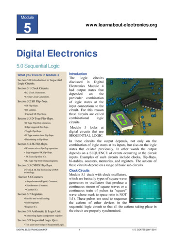
53A junior engineer offers an alternative design. He says he would change allthe 4-bit items to 3-bit (i.e., the counters, synchronizing registers, codeconverters, subtractors, etc.). In each of the two clock domains, he will havea JK flip-flop (or something similar) to remember if most recently the FIFOwas running almost empty (AE) or almost full (AF) and accordinglyinterpret a depth of 000 as zero (Empty) or eight (Full), like what was donein a single-clock FIFO.He says that this is cheaper so why not use this alternative?The junior engineer changed all [3:0] on the previous page to [2:0] as shownon the next slide and is about to add on each side one set of "JK FF andrelated circuitry" (Similar to the single clock FIFO).
WD2 [3:0]WP BinRP SS BinWP Bin[2:0]3AWENQBWCLK3 4-bit Bin SubtractorA-B2 [3:0]WDWP SS BinWP8-locationRegister ArrayWENQdepth wr 1000WENQRDdepth rd 0000RP43WCLKWP Gray43RCLKWP Gray S4 3RCLKWP Gray SS4 3Gray toBinaryCounterWP Bin[3:0]GrayCounter2EMPTYRENQWENQBinCounterWCLK3B3 4-bit Bin SubtractorA-BRDRP Bin[2:0]RP BinAWCLKREGARRAYFULL2 [3:0]WP SS Bin4 3RCLKBinCounter2 [3:0]2RP Bin[3:0]43RP SS Bin4 3Junior Engineer’sSuggestionRP Gray SS4 3RP Gray S4 3WCLKRP Gray4 3WCLKGrayCounterJKFFetc.Gray toBinaryCounterRENQJKFFetc.RCLK
55The senior engineer told him not to do that as that would create adeadlock!WP – RP 0EMPTY (if most recently it was almost empty)DON’TDOTHISFULL (if most recently it was almost full)For a 2-clock FIFO, use the (n 1)-bit counter methodonly!But WHY?! How can it cause a deadlock?
56Say FWCLK FRCLKRCLKWCLK Consider the junior engineer’sdesign with AE and AF. AE 1 when (WP-RP)mod8 2AF 1 when (WP-RP)mod8 6FULL 0ALMOST FULL 07 FIFO is initially empty.So FULL 0 and ALMOST FULL 0;EMPTY 1 and ALMOST EMPTY 16543EMPTY 1ALMOST EMPTY 121WP0RP
57RCLKWCLK Suppose the producer startswriting the data after the 1stclock edge of WCLK for 8consecutive clocks.765FULL 04ALMOST FULL 03EMPTY 1ALMOST EMPTY 121WP0RP
58RCLKWCLK765FULL 0EMPTY 14ALMOST FULL 0ALMOST EMPTY 132WP10FILLEDRP
59RCLKWCLK765FULL 0EMPTY 14ALMOST FULL 0ALMOST EMPTY 13WP21FILLED0FILLEDRP
60RCLKWCLK765FULL 0ALMOST FULL 0EMPTY 14WPALMOST EMPTY 132FILLED1FILLED0FILLEDRP
61RCLKWCLK76FULL 0ALMOST FULL 05WPEMPTY 143FILLED2FILLED1FILLED0FILLEDALMOST EMPTY 1RP
62RCLKWCLK76FULL 0ALMOST FULL 0WP54FILLED3FILLED2FILLED1FILLED0FILLEDEMPTY 1ALMOST EMPTY 1RP
63RCLKWCLK ALMOST FULL 1 as WP-RP 67WPFULL 0ALMOST FULL 165FILLED4FILLED3FILLED2FILLED1FILLED0FILLEDEMPTY 1ALMOST EMPTY 1RP
64RCLKWCLKWPFULL 0ALMOST FULL DEMPTY 1ALMOST EMPTY 1RP
65RCLKWCLK FIFO becomes full.FULL 1ALMOST FULL ED0FILLEDEMPTY 1ALMOST EMPTY 1RP
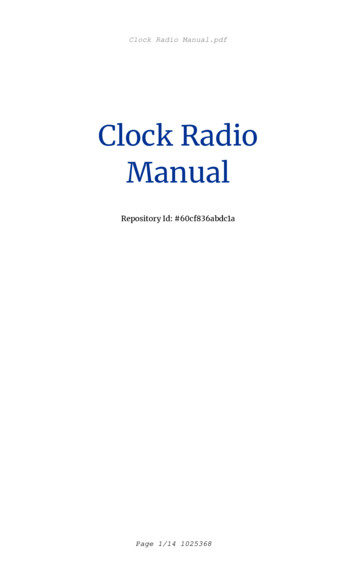
66What happens here?!RCLKWCLKThe producer sees the AF and Fullflag asserted. He infers that the FIFOis FULL because (WP-RP) 0 and7AF 1. So, he wouldn’t write into the 6FIFO any more. This is correct!5FULL 14ALMOST FULL ILLEDThe consumer sees the old (WP-RP) 0and doesn’t see the updated WP orupdated depth as he samples at avery slow rate. As a result, hecontinues to believe that the FIFO isempty. And he doesn’t read either.EMPTY 1ALMOST EMPTY 1RP
67This is a deadlock as both the Full flagand the Empty flag are high togetherand neither the producer nor theconsumer is going to take a step!!The vice versa holds true as well ifFRCLK FWCLK
7 Let us use an 8-location FIFO for our design example The FIFO has two pointers to denote the locations to write and read: Write Pointer (WP): The location pointed to by the WP is where producer deposits data. Read Pointer (RP): The location pointed to by the RP is from where consumer reads data. Initially the FIFO is empty.Both WP and RP point to location 0 of the FIFO.