Transcription
HT2000W Satellite ModemUser Guide1041264-0001Revision AFebruary 15, 201711717 Exploration Lane, Germantown, MD 20876Phone (301) 428-5500 Fax (301) 428-1868/2830
Copyright 2017 Hughes Network Systems, LLCAll rights reserved. This publication and its contents are proprietary to Hughes NetworkSystems, LLC. No part of this publication may be reproduced in any form or by any meanswithout the written permission of Hughes Network Systems, LLC, 11717 Exploration Lane,Germantown, Maryland 20876.Hughes Network Systems, LLC has made every effort to ensure the correctness andcompleteness of the material in this document. Hughes Network Systems, LLC shall not be liablefor errors contained herein. The information in this document is subject to change withoutnotice. Hughes Network Systems, LLC makes no warranty of any kind with regard to thismaterial, including, but not limited to, the implied warranties of merchantability and fitness fora particular purpose.TrademarksHUGHES and Hughes Network Systems are trademarks of Hughes Network Systems, LLC. Allother trademarks are the property of their respective owners.
ContentsContents . 3Understanding safety alert messages . 5Messages concerning personal injury. 5Messages concerning property damage . 5Safety symbols . 6Additional symbols . 6Chapter 1Satellite modem overview . 7Description . 7Operating environment . 8Ventilation and heat sources . 8Operating position . 9Computer requirements . 9Networking and Internet browser requirements . 9Contact information. 10Power supply information . 10Connecting the modem power cord. 11Disconnecting the modem power cord . 11Chapter 2System Control Center. 13Accessing the System Control Center . 13System Control Center home page . 13Indicator links . 14Parameters bar . 15Side panel . 15System Status page . 16System Information page. 17Connectivity test . 17Built-in self test . 18Chapter 3Wi-Fi Configuration . 19Getting Connected for the First Time . 19Connecting via Ethernet . 19Connecting via Wi-Fi with WPA Password. 19Connecting via Wi-Fi with WPS setup. 19Basic Setup . 20Logging into your HT2000W’s Wi-Fi configuration page . 20Changing the administrator password . 20Changing your Wi-Fi networks’ names and security settings. 21Enabling Guest Networks . 22Rebooting your HT2000W . 23Contents1041264-0001 Revision A3
Advanced Settings. 24Wireless . 25LAN. 28DNS . 30Firewall . 30NAT . 33QoS . 35Routing. 36IPv6 . 38Chapter 4LEDS. 39Front-panel LEDs . 39LAN port LEDs . 40Appendix ASpecifications . 43HT2000W modem specifications . 43Appendix BStandards compliance . 45Repairs in Canada . 45Electromagnetic interference (EMI) . 45FCC Part 15 . 46Canada Class B warning . 47Class II Radio Equipment (per R&TTE Directive 1999/5/EC) . 47Acronyms and abbreviations . 51Index . 534Contents1041264-0001 Revision A
Understanding safety alert messagesSafety alert messages call attention to potential safety hazards and tell you how toavoid them. These messages are identified by the signal words DANGER, WARNING,CAUTION, or NOTICE, as illustrated below. To avoid possible property damage,personal injury, or in some cases possible death, read and comply with all safetyalert messages.Messages concerning personal injuryThe signal words DANGER, WARNING, and CAUTION indicate hazards that couldresult in personal injury or in some cases death, as explained below. Each of thesesignal words indicates the severity of the potential hazard.DANGER indicates a potentially hazardous situation which, if not avoided, will resultin death or serious injury.WARNING indicates a potentially hazardous situation which, if not avoided, couldresult in death or serious injury.CAUTION indicates a potentially hazardous situation which, if not avoided, couldresult in minor or moderate injury.Messages concerning property damageA NOTICE concerns property damage only.NOTICE is used for advisory messages concerning possible property damage,product damage or malfunction, data loss, or other unwanted results – but notpersonal injury.Understanding safety alert messages1041264-0001 Revision A5
Safety symbolsThe generic safety alert symbolcalls attention to a potential personal injury hazard. It appears next to the DANGER,WARNING, and CAUTION signal words as part of the signal word label. Othersymbols may appear next to DANGER, WARNING, or CAUTION to indicate a specifictype of hazard (for example, fire or electric shock). If other hazard symbols are usedin this document they are identified in this section.Additional symbolsThis document uses the following hazard symbols:Indicates a safety message that concerns a potential electricshock hazard.6Understanding safety alert messages1041264-0001 Revision A
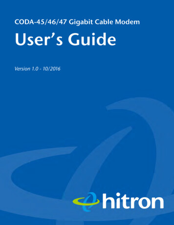
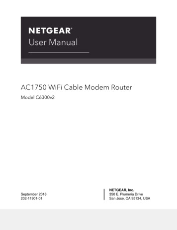
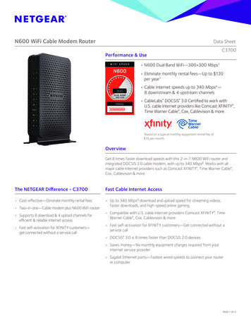
Chapter 1Satellite modem overviewThis user guide describes the features and operation of the HT2000W satellitemodem, which provides Internet access by satellite. In this user guide, satellitemodem and modem both refer to the HT2000W satellite modem.DescriptionThe HT2000W satellite modem connects to a satellite network to provide Internetservice. The modem connects to a computer or local area network (LAN) via one ofits four (4) Ethernet ports and/or its two (2) wireless networks. Figure 1 shows thefront and back of the HT2000W.After your HT2000W satellite modem has been installed, you can use yourcomputer’s web browser to access the Internet or an intranet.Figure 1: HT2000W front and backChapter 1 Satellite modem overview1041264-0001 Revision A7
Do not press the reset/rescue button on the HT2000W unless a customerservice representative tells you to do so. The USB port is provided to support a future modem feature. Hughes doesnot recommend plugging anything into this port at this time. Hughes willinform you when this feature is available.Operating environmentObserve the following requirements for the modem's operating environment.Ventilation and heat sourcesThe modem must be adequately ventilated and kept away from sources of heat. Do not block any of the modem's ventilation openings. Leave 6 inches of space around the top and sides of the modem to ensureadequate ventilation and prevent overheating. Do not place the modem near a heat source, such as direct sunlight, a radiator, aheat register or vent, oven, stove, amplifier, or other apparatus that producesheat.8Chapter 1 Satellite modem overview1041264-0001 Revision A
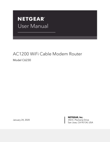
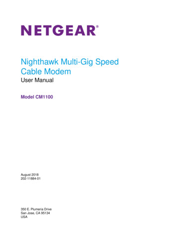
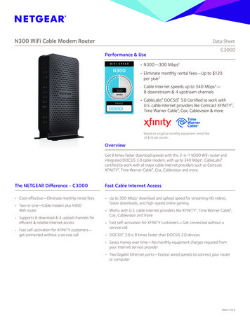
Operating positionOperate the HT2000W modem only in an upright, vertical position, resting on itsbuilt-in base, as shown in Figure 2. Any other position could result in insufficientventilation, overheating, and malfunction.Figure 2: Modem operating positionComputer requirementsThe computer that connects to the satellite modem should meet the minimumrequirements specified by the computer operating system manufacturer and thefollowing networking and browser requirements.Networking and Internet browser requirements Ethernet portEthernet network interface card (NIC) installed on your computerEthernet cableA web browser with proxy settings disabledChapter 1 Satellite modem overview1041264-0001 Revision A9
Contact informationIf you need operational, warranty, or repair support, who you should contactdepends on where you purchased your satellite modem. Please contact a customercare representative in accordance with your service agreement.Power supply information Always use the power supply provided with the satellite modem. Themodem's performance may suffer if the wrong power supply is used.Connect the power supply to a grounded outlet. A suitable surgeprotector is recommended to protect the satellite modem frompossible damage due to power surges.Always connect the DC power cord to the HT2000W rear panel beforeapplying power to the power supply. If you apply power to the powersupply and then connect the DC power cord, the satellite modem maynot perform properly and could be damaged.Observe the power standards and requirements of the country whereit is installed.If there is any reason to remove power from the satellite modem, alwaysunplug the AC power cord from the power source (power outlet, power strip,or surge protector). Do not remove the DC power cord from the modem's rearpanel. Doing so could result in an electrical shock or damage the modem.When you re-apply power to the modem, plug the AC power cord into thepower source.10Chapter 1 Satellite modem overview1041264-0001 Revision A
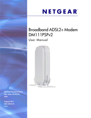
Connecting the modem power cordThe HT2000W power cord connector uses a locking mechanism to ensure it stayssnugly connected to the modem. Make sure the connector is oriented correctlywhen plugging it into the DC IN port; the flat side of the plug should face themodem’s side panel nearest to the port.Figure 3 explains how to correctly orient the power cord connector. Whenconnecting the power cord, you must push the connector into the DC IN port until itclicks. This indicates the power cord is locked into the modem.Flatside ofplugFigure 3: Aligning the power cord connectorDisconnecting the modem power cordThe power cord connector has a hard plastic sleeve (marked with two arrows) thatyou must slide backward when removing the cord from the modem. Sliding thesleeve backward disengages the connector’s locking mechanism. See Figure 4.Connector sleeveSlide sleeve to disengage locking mechanismFigure 4: Power cord connectorChapter 1 Satellite modem overview1041264-0001 Revision A11
When removing the power cord, brace the modem with one hand. Use your otherhand to slide the power connector sleeve toward you (away from the modem) andpull the power cord from the DC IN port. See Figure 5.Important: If the power cord does not easily disconnect from the DC IN port, donot force it. Doing so could damage the modem.Slide the powerconnector sleeve towardyou and pull the powercord to disconnect it.Secure the modemwith one hand.Figure 5: Disconnecting the power cord from the modem12Chapter 1 Satellite modem overview1041264-0001 Revision A
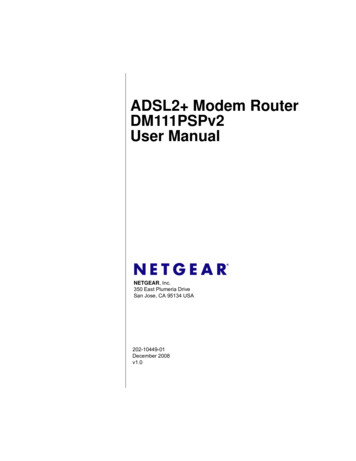
Chapter 2System Control CenterThe System Control Center is a set of screens and links you can use to monitor yourservice and troubleshoot the satellite modem in the event of a problem. The SystemControl Center provides access to system status, configuration information, andonline documentation.Access the System Control Center through a web browser on a computer connectedto the satellite modem. Use the System Control Center to find system informationfor configuring networks or to check system performance if the satellite modemdoes not seem to be functioning properly.Accessing the System Control CenterTo access the System Control Center website, first connect a computer with a webbrowser to the satellite modem's LAN port. The System Control Center is hosted onthe modem, so your computer does not have to be connected to the Internet toaccess the site.To open the System Control Center, double-click the System Control Center shortcuton your computer’s desktop, or follow these steps:1. Open a web browser.2. In the browser address bar, type 192.168.0.1 and press Enter.System Control Center home pageThe System Control Center home page contains numerous links to satellite modemfeatures and important information regarding operation of your satellite modem.Figure 6 shows the System Control Center home page. Your home page may lookslightly different depending on your service provider.Chapter 2 System Control Center1041264-0001 Revision A13
Figure 6: System Control CenterIndicator linksAt the top of each System Control Center page are two indicators followed by a textlink (Figure 7), as well as a language selection drop-down.Figure 7: Indicators and linksEach text link navigates to a page in the System Control Center. Table 1 describesthe destination page for each link.Table 1: Destination pagesIndicatorDestinationDescriptionSystem StatusSystem Status pageGives important information aboutthe satellite modem’s operationalstatus.System InformationSystem Information pageGeneral information screen thatidentifies software and hardwareversions and other importantsatellite connection information.The System Status indicator also changes color to indicate the operational status ofthe satellite modem.14Chapter 2 System Control Center1041264-0001 Revision A
Red: The system has a problem. Yellow: The system is operational, but under a degraded condition. Green: The system is functioning within normal parameters.Parameters barThe parameters bar appears at the top of all System Control Center screens asshown in Figure 8. This bar displays three important fields of information: SAN – Site account number (SAN), which identifies the installation site. ESN – Electronic serial number assigned to the modem. Diagnostic Code – Used to troubleshoot problems.Figure 8: Parameters barSide panelThe following links appear on the left side panel of each System Control Centerscreen as shown in Figure 9.Figure 9: Side panel linksHomeOpens the System Control Center home page.Connectivity TestOpens the Connectivity Test page, which you can use to test the connectionbetween the satellite modem and the NOC.Built-In Self TestChecks the internal operation of the modem.Chapter 2 System Control Center1041264-0001 Revision A15
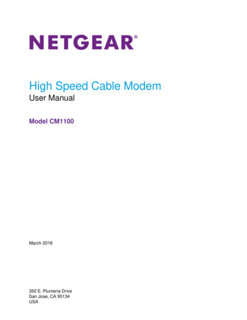
WiFi SettingsAllows the user to customize certain aspects of the modem’s Wi-Fi functionality.Note: Some of these links may not appear because they are not enabled by theservice provider.System Status pageThe System Status page lists parameter information vital to the proper operation ofthe HT2000W. Available system status values (as shown in Figure 10) may vary,depending on how your satellite modem is configured.Figure 10: System Status page16Chapter 2 System Control Center1041264-0001 Revision A
System Information pageThe System Information page (shown in Figure 11) provides system information forthe satellite modem, such as identification information, software versions, andsatellite information.Figure 11: System Information pageConnectivity testTo test your connectivity:1. Click the Connectivity Test link on the side panel. The Terminal/GatewayConnectivity Test panel appears in the center of the screen.2. Click Start the test, as shown in Figure 12.Figure 12: Starting the connectivity test3. A progress bar appears in the Terminal/Gateway Connectivity Test panel,indicating the test has started.Chapter 2 System Control Center1041264-0001 Revision A17
4. When the test completes, the results appear in the center panel. Figure 13shows the results of the test.Figure 13: Connectivity test resultsBuilt-in self testUse the Built-In Self Test link on the side panel to check the connectivity of thesatellite modem. To initiate the test:1. Click the Built-In Self Test link on the side panel.2. The test results appear in the BIST Results panel, as shown in Figure 14.Figure 14: Built-In Self Test screenNote: If the Built-In Self Test fails, contact Customer Care at 1-866-347-3292for assistance.18Chapter 2 System Control Center1041264-0001 Revision A
Chapter 3Wi-Fi Configurati
February 15,2017 ; 11717 Exploration Lane, Germantown