Transcription
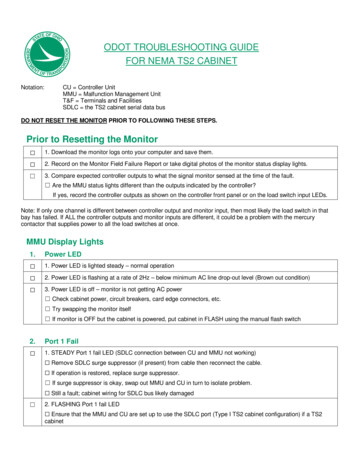
ODOT TROUBLESHOOTING GUIDEFOR NEMA TS2 CABINETNotation:CU Controller UnitMMU Malfunction Management UnitT&F Terminals and FacilitiesSDLC the TS2 cabinet serial data busDO NOT RESET THE MONITOR PRIOR TO FOLLOWING THESE STEPS.Prior to Resetting the Monitor 1. Download the monitor logs onto your computer and save them. 2. Record on the Monitor Field Failure Report or take digital photos of the monitor status display lights. 3. Compare expected controller outputs to what the signal monitor sensed at the time of the fault. Are the MMU status lights different than the outputs indicated by the controller?If yes, record the controller outputs as shown on the controller front panel or on the load switch input LEDs.Note: If only one channel is different between controller output and monitor input, then most likely the load switch in thatbay has failed. If ALL the controller outputs and monitor inputs are different, it could be a problem with the mercurycontactor that supplies power to all the load switches at once.MMU Display Lights1.Power LED 1. Power LED is lighted steady – normal operation 2. Power LED is flashing at a rate of 2Hz – below minimum AC line drop-out level (Brown out condition) 3. Power LED is off – monitor is not getting AC power Check cabinet power, circuit breakers, card edge connectors, etc. Try swapping the monitor itself If monitor is OFF but the cabinet is powered, put cabinet in FLASH using the manual flash switch2.Port 1 Fail 1. STEADY Port 1 fail LED (SDLC connection between CU and MMU not working) Remove SDLC surge suppressor (if present) from cable then reconnect the cable. If operation is restored, replace surge suppressor. If surge suppressor is okay, swap out MMU and CU in turn to isolate problem. Still a fault; cabinet wiring for SDLC bus likely damaged 2. FLASHING Port 1 fail LED Ensure that the MMU and CU are set up to use the SDLC port (Type I TS2 cabinet configuration) if a TS2cabinet
3.Conflict (Conflicting Signals Detected) 1. Observe load switches and compare with controller outputs to see if they match. 2. Tighten screws at field terminals and check for crimped-on terminals at the field terminal barrier strip. 3. Check load switches visually for proper outputs. Do controller outputs match the display load switches? 4. Look for burned out lamps on previously serviced phases.Note: It is possible for LED signal lamps to be lit, but still appear to the MMU as faulty.4.Red Fail (Dark channel/phase with no visible/sensed output by MMU on that channel) 1. STEADY (Red Fail Fault detected) All channels show Red Fail-Could be bad mercury contactor or dead/slow-starting controller One channel shows RED FAIL Most likely a broken load switch on that channel2. FLASHING (Red Fail indicator will FLASH once every 2 seconds if the RED ENABLE input to the MMU is notactive. Check cabinet wiring of Red Enable5.CVM/WD (MMU does not receive proper input signal from controller) 1. Verify that the programmed MMU phase permissive pairs are the same as the programmed controllerpermissive pairs. 2. CVM/WD is on, even though CU and MMU phase permissive pairs match- Likely causes: controller malfunction, MMU malfunction Try replacing CU first; if unsuccessful, replace MMU6.24V-1, 24V-2 LED 1. FLASHING – a 24V MONITOR INHIBIT input is provided to inhibit the operation of the 24Vdc Monitor 2. STEADY – the indicated 24V power supply input has dropped below the acceptable voltage level Check fuses on the DC power supply and replace any blown fuses If fuses are okay, replace DC power supply-If unsuccessful, the MMU or wiring is probably bad.7.Clearance Fail (Minimum Yellow Change Interval) 1. Monitor indicates a Yellow Clearance Fail. Short yellows are intermittent, but usually are the result of a badcontroller. 2. Reset the monitor and observe the intersection for a while to see if the MMU trips on short yellow again. MMU trips on Yellow Clearance on the same channel repeatedly MMU trips on Yellow Clearance on different channels- If neither of these work, it is most likely a bad controller or there is bad AC power at the cabinet.3. Check the incoming power to be sure it is a nice clean sine wave
8.Y R Clearance 1. Verify that All-Red clearance intervals for each channel with a Short Yellow Disable Jumper on theprogramming card are at least 3.0 seconds. 2. If monitor indicates a Y R Clearance Fail, try resetting the monitor and observing the intersection for a whileto see if the MMU trips on Y R again. If so: MMU trips on Y R Clearance on the same channel repeatedly; try new load switch MMU trips on Y R Clearance on different channels-If the above steps do not work, it is most likely a bad controller or there could be bad AC power at thecabinet. 3. Check the incoming power to be sure it is a nice clean sine wave9.Dual Indication (Detects simultaneous input combinations on the same channel) 1. Dual indication LED is lit, one or more LED signals on that channel are dark Replace the signal lamp(s) 2. Dual indication LED is lit, but the multiple colors indicated on the monitor are still being displayed by thoseLED lamps in the signal heads Check and clean the terminal strip in the signal head if corrosion from water intrusion is suspected Replace the LED signals lamp(s) that come first in the indicated dual sequence (i.e. replace green LED ifGY dual indicated; replace yellow LED if RY dual indicated, etc.)10.Field Check Fail 1. Is only one channel showing field check fail? 2. Is more than one channel showing field check fail?Note: If one of the above is true, it is most likely a bad T&F BIU or bad controller.11.PGM CD/CF (Programmed Card Absent/Configuration Change) 1. LED is ON steady – Program Card Absent 2. LED is flashing – Configuration Change If configuration is valid, press reset button for 5 full seconds to clear this fault and log the newconfiguration parameters. Carefully check the Programming Card to make sure it matches the configuration of the intersectionbefore you hold the extend reset button to make change permanent. Check for poor solder joints and carefully re-solder them if the look compromised.12. Local Flash1. Local flash LED is lit and signal is on flash. Check technician and police door toggle switches to see they have not been accidentally turned to flash13. Diagnostic1. Diagnostic LED is lit (usually a bad MMU) Remove and replace MMU
14. Type Fault1. Type 12 LED is flashing- Most likely a cabinet wiring problem related to the TYPE SELECT input 2. Type 12 LED on steady- Normal state for an MMU being used as a 12-channel monitor in a TS1 cabinet
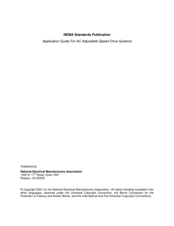
MONITOR FIELD FAILURE REPORTIntersection:Time back on:Date:CONFLICTING PHASES12345b REDcdefgb YELLOWcdefgb YELLOWcdefgb YELLOW gcdefgb YELLOW gcdefb YELLOW gcdefb YELLOWcdefb YELLOW gcdefgb YELLOWcdefb GREENcdefgb GREENcdefgb GREENcdefgb GREENcdefgb GREENcdefgb GREENcdefgb GREENcdefgb GREENcdefgb WALKcdefgb WALKcdefgb WALKcdefgb WALKcdefgb WALKcdefgb WALKcdefgb WALKcdefgb WALKcdefg111213b REDcdefg14b REDcdefg15b REDcdefgb YELLOWcdefgb YELLOWcdefgb YELLOW fcdefgg YELLOW fbcdeg YELLOW fbcdeg YELLOWbcdeb YELLOW fcdefgg YELLOWbcdeb GREENcdefgb GREENcdefgb GREENcdefgb GREENcdefgb GREENcdefgb GREENcdefgb GREENcdefgb GREENcdefgb WALKcdefgb WALKcdefgb WALKcdefgb WALKcdefgb WALKcdefgb WALKcdefgb WALKcdefgb WALKcdefgb AC POWERcdefgbcdefgb CONFLICTcdefgbcdefgb RED FAILUREcdefgbcdefgb WATCHDOG ERRORcdefgbcdefgb VDC FAILEDcdefgbcdefgb DUAL INDICATIONcdefgbcdefgb DIAGNOSTICcdefgbcdefgb PROGRAM CARDcdefgbcdefgb BNDcdefgbcdefgb SEQUENCEcdefgbcdefgb RP 45678910111213141516b REDcdefg16b REDcdefgSSM SWITCHES ONb REDcdefgb REDcdefgb REDcdefgFAILURE INDICATIONb REDcdefgb REDcdefg8b REDcdefg10b REDcdefg7b REDcdefg9b REDcdefg6b REDcdefgOPTIONSb GY ENABLEcdefgb RP DISABLEcdefgb WD ENABLEcdefgb WALK DISABLEcdefgb CF ENABLEcdefgb CVM LOG DISABLEcdefgb BND DISABLEcdefgb VM LATCHcdefg
Check and clean the terminal strip in the signal head if corrosion from water intrusion is suspected Replace the LED signals lamp(s) that come first in the indicated dual sequence (i.e. replace green LED if GY dual indicated; replace yellow