Transcription
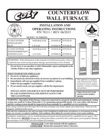
COUNTERFLOWWALL FURNACEINSTALLATION ANDOPERATING INSTRUCTIONSP/N 78111 / REV. 06/2015MODEL NUMBERS24 VOLT SYSTEMWITH LOW-BTUPILOT24 VOLT SYSTEMWITH INTERMITTENTIGNITION (I.I.D.)NATURAL GASCF403D-H CF553D-HL.P. GASCF404D-H CF554D-HNATURAL GASCF407D-H CF557D-HL.P. GASCF408D-H CF558D-HWARNING: If the information in this manual is not followed exactly, a fire orexplosion may result causing property damage, personal injury or loss of death.-Do not store or use gasoline or other flammable vapors and liquids in thevicinity of this or any other appliance.WHAT TO DO IF YOU SMELL GAS: Do not try to light any appliance. Do not touch any electrical switch; do not use any phone in your building. Immediately call your gas supplier from a neighbor’s phone.Follow the gas supplier’s instructions. If you cannot reach your gas supplier, call the fire department.-INSTALLATION AND SERVICE MUST BE PERFORMEDBY A QUALIFIED INSTALLER, SERVICE AGENCY ORTHE GAS SUPPLIER.This appliance is equippedwith a blocked flue switchdesigned to protect againstimproper venting of combustion products.THIS UNIT IS NOT TO BEINSTALLED IN MOBILEHOMES.WARNING: Operation of this furnace when not connected to a properly installed and maintained ventingsystem can result in Carbon Monoxide (C.O.) poisoning and possible death. For your safety, this furnaceand the venting system should be inspected at least annually by a qualified service technician.The coating selected to provide longer life to the heat exchanger may smoke slightly upon initial firing. Please provideadequate ventilation if this occurs.This unit is for residential use only and is not approved for installation in mobile homes, greenhouses, or environments involvingdusty, wet, corrosive, or explosive conditions. Such conditions will invalidate the warranty and may create unsafe conditions.Installation, maintenance, service, troubleshooting and repairs must be performed by a qualified service agency. Mr./Mrs. Homeowner, DO NOT attempt any of these procedures yourself as this could expose you to property damage,personal injury or loss of life and will invalidate all warranties.INSTALLER: Leave this manual with the appliance.CONSUMER: Retain this manual for future reference.
The State of Massachusetts requires that installation and service of a gas appliance be performedby a plumber or gas fitter licensed in the Commonwealth of Massachusetts.CONTENTSContents . 2Introduction . 2Specifications . 2Safety Rules 3Helpful Installation Information . . 3Connecting the Vent . . 3,4Combustion and Ventilation Air. 5Furnace Location . . 6Rough-In Instructions . . . 6,7Installation . . 8Controls . . 9Pilot Flame Adjustment . . 9Lighting & Re-Lighting Instructions . 10,11Operation . . 12Terminal Block Wiring Diagram . 13Manual Reset . . 13Maintenance Instructions . 13Wiring Diagram . . 14Side & Rear Discharge Kits . 15,16Trouble Shooting Chart . . 17-19Repair Parts (break down) . . 20-25Repair Parts List . . 20-25Possible Causes & Corrective Action. 19Warranty . . 26INTRODUCTIONTHIS IS A GAS-FIRED, GRAVITY VENTED WALL FURNACE THAT WILL OPERATE SAFELY AND PROVIDE AN EFFICIENTSOURCE OF HEAT WHEN INSTALLED, OPERATED AND MAINTAINED AS RECOMMENDED IN THESE INSTALLATIONAND OPERATING INSTRUCTIONS. READ THESE INSTRUCTIONS THOROUGHLY BEFORE INSTALLING, SERVICING, ORUSING THE APPLIANCE. IF YOU DO NOT UNDERSTAND ANY PART OF THESE INSTRUCTIONS CONSULT LOCALAUTHORITIES, OTHER QUALIFIED INSTALLERS, SERVICE TECHNICIAN, THE GAS SUPPLIER, OR THE MANUFACTURER.COUNTERFLOW WALL FURNACE SPECIFICATIONSYour counterflow wall furnace is packed in a single carton that also includes thermostat, thermostat wire, and insulated staples.The thermostat, wire, and staples are packed in the burner compartment and are accessible by removing the burner access door.While the burner access door is open, check the rating plate to verify that the model number is correct and that the wall furnaceis equipped for the type gas you intend to use.Model TypeTypeNumber Control GasBTU/HR.InputVentSize(Oval)GasInletFinished DimensionsBlowerSpeed Amps CFMApprox.ShippingWeightMODELS WITH LOW-BTU STANDING PILOTCF403D-H 24 VoltCF404D-H 24 VoltCF553D-H 24 VoltCF554D-H 24 5/16”H11112.252.252.252.25440440440440104 Lbs.104 Lbs.107 Lbs.107 lbs.440440440440104 Lbs.104 Lbs.107 Lbs.107 Lbs.MODELS WITH INTERMITTENT IGNITIONCF407D-HCF408D-HCF557D-HCF558D-H24 Volt Nat.24 Volt L.P.24 Volt Nat.24 Volt 7-5/16”H14-5/16”Wx10¼”Dx87-5/16”HPage 211112.552.552.552.55
SAFETY RULES1.2.3.4.5.6.7.8.9.10.11.12.13.14.Improper installation, adjustment, alteration, service or maintenance can cause property damage, bodily injury or death. If youdo not understand these instructions or your local codes, call local authorities, a qualified installer, service agency, gas supplier,or the manufacturer.Do not install this fan type wall furnace in a recreational vehicle trailer or mobile home.Do not operate this fan type wall furnace unless it is connected to a properly installed and maintained vent system. Do notexhaust flue gases into the room, wall or attic space for any reason.Locate the thermostat in a room or space that cannot be separated by a door or other means from the room or space in which thefront outlet grill is installed.Adequate air for combustion and venting must be provided.If rising water may enter the wall furnace, turn off the gas immediately and disconnect the electric service. Do not use the wallfurnace if any part has been under water. Immediately call a qualified service technician to inspect the wall furnace and to replaceany part of the control system or any gas control which has been under water.Have your fan type wall furnace and vent system inspected at least annually by a qualified service technician.Before cleaning or servicing the wall furnace, turn off the gas and allow it to cool. This will prevent burns.Due to high temperatures, the furnace should be located out of traffic and away from furniture and draperies.Children and adults should be alerted to the hazards of high surface temperatures and should stay away to avoid burns orclothing ignition.Young children should be carefully supervised when they are in the same room as the furnace.Clothing or other flammable material should not be placed on or near the furnace.Any safety screen guard or gill removed for servicing must be replaced prior to operating the furnace.Locate the blocked flue switch and the auxiliary limit switch and push in the reset button. This will reset the switch in case itaccidentally opened during shipping.READ CAREFULLY BEFORE INSTALLING UNITThe installation must conform with local codes, or in the absence of local codes, with the National Fuel Gas Code, ANSI Z223.1/NFPA54 or the Natural Gas and Propane Installation Code, CSA B149.1.The appliance, when installed, must be electrically grounded in accordance with local codes or, in the absence of local codes, thelatest edition of the National Electrical Code, ANSI/NFPA 70. In Canada, see latest edition of CSA C22.1 if an external electrical sourceis utilized.The ANSI standards are available from the American Gas Association, 1515 Wilson Blvd., Arlington, Virginia 22209.The NFPA standards are available from the National Fire Protection Association, Batterymarch Park, Quincy, MA. 02269. Canadianstandards are available from International Approval Services, 178 Rexdale Blvd., Etobicoke, Ontario, Canada M9W 1R3.VENTINGThis appliance must be properly connected to a venting system. Consult local ordinances governing venting. Install only UL listed typeBW 4” oval gas vent. When the vent enters the attic, a listed type B-1 round flue pipe may be used. See Figure 1, Page 4.Vent pipe must connect to the wall furnace or header plate with a “B” vent base plate and terminate with a cap at a point at least 12 ft. abovethe bottom of the wall furnace and two feet above any obstacle within a 10 foot radius and at least 3 foot above the roof.Provisions must be made for adequate combustion and ventilation air. This appliance must not be connected to a chimney flue serving aseparate solid fuel burning appliance.All type “B” vents shall extend in a generally vertical direction with offsets not exceeding 45 degrees, except that a vent system having notmore than one 60 degree offset may be allowed.Any angle greater than 45 degrees from the vertical is considered horizontal. The total horizontal run of a vent plus the horizontal ventconnector shall be not greater than 75 percent of the vertical height of the vent. Any offsets used should be as far above the drafthood aspossible to allow a venting action to begin before any restriction is encountered.Page 3
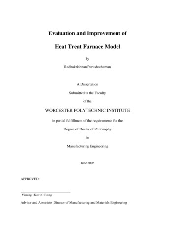
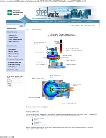
VENTING - CONTINUEDMorethan 10’10’Ridge10’ orLessHeight above anyroof surfacewithin 10’horizontally2’ Min.2’ Min.Ridge3’ Min.3’ Min.ChimneyChimneyFIGURE AThis appliance is equipped with a blocked flue switch.WARNING: Do not bypass the blocked flue switch. Todo so could expose the consumer to property damage,personal injury or possible death.This switch, when activated, will interrupt the electrical circuit betweenthe transformer and the gas valve causing the main burner flame toextinguish. The main burner will not re-light until the blocked flue switchhas been manually reset. To reset the switch, after locating it betweenthe bottom of the fan shroud and the top of the draft diverter, simplypush the red button on top of the switch. If the homeowner experiencesthis problem, then the vent system must be checked and corrected.NOTE: An existing vent that has worked for years may not be adequatefor today’s appliances because of higher efficiency requirements thatresult in lower stack temperatures.3’ListedVent TopStorm Collar2’ Min.RoofFlashingOval to roundadapterListed “BW”Vent Pipe12’Min.Base PlateCeilingPlateSpacerLancesHeaderPlate2x4 WallStudWARNING: Operation of this wall furnace when not connected to aproperly installed and maintained venting system or tampering withthe blocked flue switch can result in Carbon Monoxide (CO)poisoning and possible death.(SEE LIST OF POSSIBLE CAUSES AND CORRECTIONS ON PAGE 19).FIG. 1 - VENT INSTALLATIONAll type “B” vents shall extend in a generally verticaldirection with offsets not exceeding 45 degrees, exceptthat a vent system having not more than one 60 degreeoffset may be allowed.RedButtonAny angle greater than 45 degrees from the vertical isconsidered horizontal. The total horizontal run of a ventplus the horizontal vent connector shall be not greaterthan 75 percent of the vertical height of the vent.BlockedFlueSwitchAny offsets used should be as far above the drafthood aspossible to allow a venting action to begin before anyrestriction is encountered.Draft DiverterRelief Opening“CF40/55-D” Series CounterflowPage 4
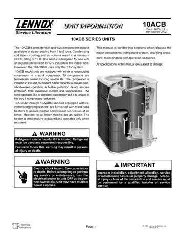
COMBUSTION AND VENTILATION AIRWhen installed, this gas appliance must be provided with freshair for combustion, ventilation, and dilution of hot flue gases.The minimum required volume of the area where the appliance isinstalled should be 50 cubic feet per 1,000 btu/hr.If installed in an area of the home that is considered an unconfinedspace, the natural infiltration of air around windows and doorswill be adequate. If the area is considered a confined space (lessthan 50 cubic feet per 1,000 btu), fresh air can be supplied byproviding two permanent openings into adjoining rooms. Eachopening shall have a minimum free area of one square inch per1,000 btu per hour of the total input rating of all gas appliances inthe confined space, but not less than 100 square inches. One ofthe openings shall be within 12 inches of the ceiling and onewithin 12 inches of the floor. See Figure A.If the home is of unusually tight construction (new and remodeledhomes), free air must be supplied through opening(s) to theoutdoors. This can be accomplished by providing 2 permanentopenings, one commencing within 12 inches of the ceiling andone within 12 inches of the floor. These openings shallcommunicate directly with the outdoors, or spaces thatcommunicate freely with the outdoors, such as a ventilated atticand crawl space through galvanized or equivalent corrosionresistant ducts. Exception: unobstructed stud and joist spacesare acceptable ducts provided that not more than one fire blockis removed. Special provisions must be taken to insure thatthese stud and joist spaces cannot be blocked with insulation orother objects. Each of these openings using vertical ducts shallhave a minimum free area of one square inch per 4,000 btu/hr oftotal input rating of all gas appliances. See Figure B and C. Ifhorizontal ducts are used, the minimum free area shall be onesquare inch per 2,000 btu/hr of total input rating of all gasappliances.Fresh make-up air can also be provided through a duct to onepermanent opening commencing within 12 inches of the ceiling.The minimum free area of this opening shall be one square inchper 3,000 btu/hr of the total input rating of all gas appliances butnot less than the sum of the areas of all vent connectors in thespace. See Figure D.When calculating the amount of fresh air needed you must includemake-up air requirements for the operation of exhaust fans, kitchenventilation systems, clothes dryers, and fireplaces.Additional information can be found in the latest edition of ANSIZ223.1 (National Fuel Gas Code).Page 5FIGUREALL COMBUSTION
standards are available from International Approval Services, 178 Rexdale Blvd., Etobicoke, Ontario, Canada M9W 1R3. VENTING This appliance must be properly connected to a venting system. Consult local ordinances governing venting. Install only UL li sted type BW 4” oval gas vent. When the vent enters the attic, a listed type B-1 round flue .