Transcription
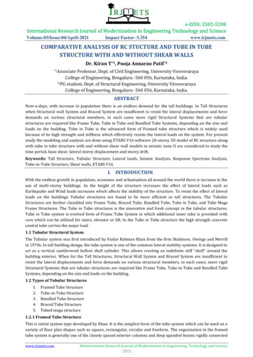
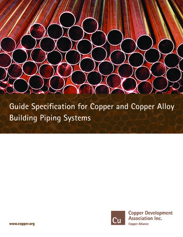
Tube alloy degradation in a steamcracking furnaceUnderstanding catalytic coke growth mechanisms to better predict andoptimise furnace service times with tube alloy degradationGLEN A HAY and GHONCHEH RASOULI Virtual Materials Group, Inc.TOSHIHARU MORISHITA and JINICHIRO USAMI Mitsubishi Chemical CorporationIn order to optimise servicerun length for a steam cracking furnace it is essential tounderstandtheconditionssurrounding and including thetube coil for that run. Theserunning conditions, such astemperatures, pressures andsteam dilution, allow cokegrowth trends to be predictedand minimised to ensure themost favourable plant operational economics. In order tounderstandandoptimisetrending of multiple serviceruns throughout the life spanof the tube coils, differentconsiderations must be takeninto account. This articlereviews a simulated case studyusing the software packageVMGSim1 to explain the mechanisms causing reduced runtimes over the lifespan of atube coil at a MitsubishiChemical plant site in Kashima,Japan.Coke formation mechanismsCoke formation in an ethylenecracker reduces the tube crosssection, the heat flux to thereacting gas mixture and yield;it increases pressure drop andconsequently reduces servicewww.eptq.comAlloy composition inputs for a simulated coke growth modelMetal content, 0.80Inconel 600Inconel 800Ni wt%001030807732Cr wt%021830201621Fe wt%1009872400747Table 1time. Coke growth can happenthrough pyrolytic and catalyticmechanisms. Both mechanismsplay an important part in theformation of coke within tubecoils in a cracking furnace. Atthe early stages, coke formationmainly occurs through thecatalytic mechanism. This typeof coke growth is driven by thetube alloy itself when metalsites such as iron or nickel arecontacted by process materialandfilamentouscokeisproduced. Detailed kineticmodels of this can be developed by including surfacereactions,segregationprocesses, and the diffusion ofcarbon through specific metalparticles such as nickel.2Chromium content in the tubescan be used to inhibit the catalysing effects of tube metalsand is often found in higherservice temperature tube coilmaterials such as Inconel orHK40.3 One must be carefulregarding less obvious effectsof trace components in the tubealloys such as silicon andaluminum and the interactionsbetween iron, nickel and chromium content that make anydirect correlations cumulativelyincorrect (see Table 1).Over time, pyrolytic cokegrowth soon becomes thedominant mechanism withinthe remaining service time ofthe furnace tube coils. Thismechanism is directly relatedto the concentration of compo-PTQ Q2 2015 1
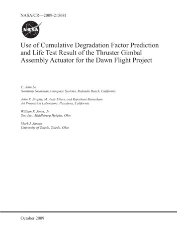
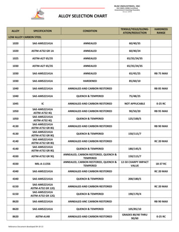
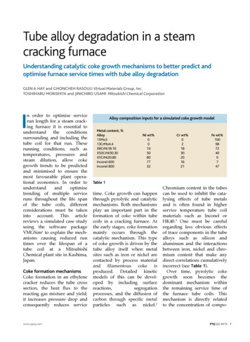
nents within the processmaterial and the running pressure and temperature. Thesimulation model developedand used for the analysiswithin VMGSim applied amolecular structure-type modelfor prediction of the cokegrowth rate profiles throughout the tube coil using thePIONA oil characterisationenvironment.5,6 Coke formationfrom each type of moleculargroup is predicted and generalkinetic rates could be derivedfrom open literature using thisgeneralised structure.7,8,9 Theclassifications and groupingsfor kinetic rates in many of thepapers available showed typesof molecular structures fromolefin to more dehydrogenatedand ringed components werealready recognised as differentinfluencestowardsoverallpyrolytic coke growth rates.A combined equation todetermine coke growth isshown (see Equation 1) wherethe first term consists solely ofpyrolytic coke formation andprovides an asymptotic growthrate:rCoke rAsym * (1 rCat * lThick) (1)where rAsym is asymptoticcoke growth due to pyrolyticcoke formation, which is afunction of the local temperature,pressure,andcomposition; rCat is catalyticrate of coke formation, whichis a function of the tube alloymaterial; and lThick is thicknesseffect related to coke thickness,that is a function of the localcoke thickness.Alloy degradation effects onservice run timesAs coke builds on the inside of2 PTQ Q2 2015the tube coils, the addedroughness, reduced internaldiameter and heat flux resistance cause the inlet coilpressure and furnace boxtemperatures to increase tokeep outlet product specificationsconstant.Onceamaximum tube coil temperature or pressure drop isreached, the inner tube coilmust be cleaned. In this processof decoking, the tube coilmetallurgy is affected and themetal content of the surface ofthe tube coil changes. Regularoperation of the crackingfurnace also alters the composition of the tube surface as iron,nickel, chromium and otherelements can be found in cokeformed within the coil duringservice time.7Possibilities of tube coatingand feed inhibitorsTube coatings come in the formof aluminum, magnesium, zinc,and other metals and theirassociated oxides. These coatings are specifically good atreducing catalytic coke growthsince they hide the iron andnickel sites that would typicallycatalysethecokeformation surface reactions.10Inhibitors used are commonlysulphur, phosphorous, aluminum, or silicon based and alsofocus on reducing the catalyticcoke growth by passivating themetal surface.11,12In order to bring the effect oftube coatings or feed inhibitorsinto the simulation model, theoverall coke growth rate iscalculated using Equation 2:rCoke rAsym * rAsymInhib* (1 rCat * lThick *rCatInhib) (2)where rAsymInhib is a reduction inasymptotic coke formation dueto using inhibitors or coatings;and rCatInhib is a reduction incatalytic coke formation due tousing inhibitors or coatings,which is a function of tubecoating or feed inhibitor effectson the catalysed coke growthmechanism.Although this study focusedmostly on the changing contentof tube alloy, the roughness ofthe tubes is also suspected ofplaying a role in the reducedservice time seen in older tubecoils. In addition, the metalsdeposit as oxide films and theireffect is not as simple as directweightpercentages,asdescribed here, and carburisedlayers are created where carboncan more easily intrude. Theseare two details of the servicetime performance over tubeaging that could potentially befurther refined if more performance data and analysis wereavailable.ResultsThe built layer of coke thickness within the tubes also actsas a major parameter of howcatalytic coke growth rates aredetermined. As the coke layerbecomes thicker, diffusion ratesthrough the coke slow the ratesof material mass transfer to apoint where this catalyst typecoke growth becomes negligible. This transition from wherecatalyst growth is dominant tothat where it is negligibledepends on the growth rates ofthe coke itself, but can rangefrom hours to days in an ethylene cracking furnace. Figure 1shows model predictions ofcoke growth rates as comparedto literature from the catalyticdominated regions to the pyrolytic dominated region forwww.eptq.com
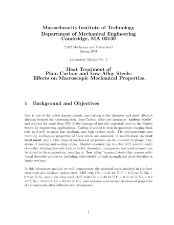
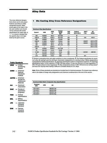
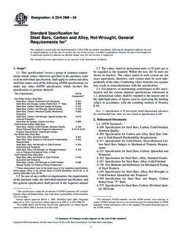
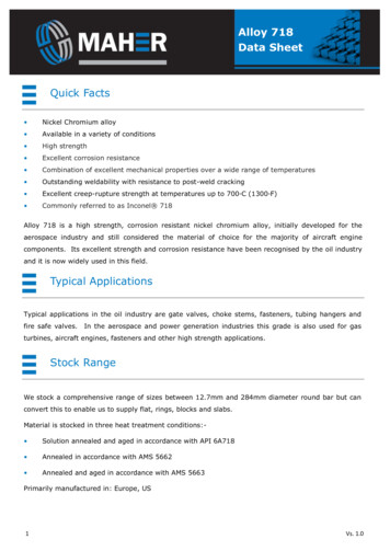
52.02.5rN2.53.0C3.0Coke thickness0 mmCatalytic0.05 mm0.10 mm0.15 mm0.20 mm0.25 mmPyroytic0.30 mm3.5C3.54.0X8Coke formation, 103µg/cm2.hService time first hourService time second houro3Coke formation, 103µg/cm2.h4.0MaterialMaterialFigure 1 Pyrolytic versus catalytic coke growth model comparisonswww.eptq.comcoil to 4-6 wt% at the end ofthe tube’s life. Figure 2 showsthe results from two separatesimulation model runs whereinitial and older tube contentwas entered for the servicetime runs. If the resultingfurnace temperature and pressure drop are dependent on aset coke maximum thickness,20% differences in service timecan easily be encountered. Theconstant coke growth rate afterCoke thickness, mm4.54.03.5initial catalyst coke growth isdue to equivalent operationalinputs being used and therefore equal pyrolytic growthrates were determined.The speed at which the chromiumcontentdecreased,therefore reducing the lengthof each service run, could betrended when looking at theplant’s operational data. Figure3 shows the operational serviceruns versus the run number forLow Cr% (older tubes)High Cr% (newer tubes)3.02.52.0 Catalysedgrowth1.5 20% Λ service 0141/209/01/2014001/0different tube alloys. It is obvious how the effects ofchromium content for the inhibition of coke growth – fromthe metal contents used asinput into the model given inTable 1 – compared to observations from specific tube alloysprovided by Zimmermann etal4 in Figure 1.Unfortunately, the chromiumcontent of the tube candecrease quicker than the ironand nickel contents, and thesimulation model predictedhigher initial catalytic cokegrowth from the new apparenttube coil metal content withlessinhibitingmake-up.Service times can be heavilyover-predictedoverthelifespan of the tube coils if thisalloy degradation is left out ofa coking simulation model forthe reactor. Analysis of tubecoil from the Kashima plantconfirmed this type of tubealloy degradation and showedchromium content on thetube’s inner surface fallingfrom 30-35 wt% in a new tubeFigure 2 New vs old tube coke growth profilesPTQ Q2 2015 3
Run length, days4030201000102030405060708090Service runFigure 3 Run length for ethane feed unit in terms of service run (with outliersremoved)one of the ethane crackingfurnaces. The severity ofservice runs being reduced bymore than half is shown andpoints to the importance ofunderstanding and planningfor these trends. A similartrend could be observed in thesimulation model when thetube alloy content used asinput was updated per run.This was mainly due to a sharpincrease in the coke thicknessat the start of the run times asseen in the older tube profile inFigure 2.In Figure 4, the coke formation rate as a function ofdimethyl disulphide (DMDS)inhibitor is shown for asymptotic and catalytic coke typesfrom experimental data andcorrelated using equation 2.Figure 4 shows that the correla-Coke growth rate, g/cm2.h0.0025Asym experimentalCat experimentalCat correlationAsym 0001000012000Thiophene, ppmFigure 4 Coke formation rate as a function of thiophene inhibitor for two typesof asymptotic and catalytic coke formation (experimental data11 and correlationgiven in Eq.2)4 PTQ Q2 2015tion used in VMGSim agreeswell with experimental dataand illustrates the reducingeffects of DMDS on cokegrowth rate for either asymptotic or catalytic conditions.11Even though the tube’s metalcontent changes during the lifeof tube coils there are stillinhibiting solutions available tokeep longer run times. Thesesolutions include tube coatingand feed inhibitors since theydo not directly relate to theoperationalconditions.Solutions such as increasedsteam dilution work to alimited degree, but keepingconstant outlet yields with theresulting reduced residencetimes requires increased coiltemperatures and decreasesany significant advantagesgained.ConclusionsIn this study the inevitabledegradation of tube coil alloyover time was reviewed alongsidemeasuredalloycompositions and recordedservice run lengths. Chromiumdepletion in the inner tube coilsurface and resulting increasedcatalytic coke growth ratescaused the service run lengthtimes to decrease over time.Plant data showed chromiumcontent falling from 30-35 wt%down to 4-6 wt% over thetube’s life. During this time,run lengths were found todecrease to less than half thepossible days when the tubeswere new. The use of differenttube coatings and feed inhibitors was then suggested as apotential application to mitigatethis problem and prolong tubecoil lifespan without alteringoperationalconditions.Addition of dilution steam as awww.eptq.com
solution to prolong servicetimes was seen as less affectivedue to increased coil temperatures and therefore faster cokegrowth rates in order to matchproductyields.Furtherimprovements to the simulation model of coke growth overtube coils would potentiallycome from the addition ofroughness and metal oxideformation details, althoughmore data would be requiredfor confirmation of these effectsto coke growth and theirquantification.AcknowledgementThe authors are grateful for thesuggestions, support, and overallcontribution of knowledge from Otasan of Mitsubishi Chemical Corporationthroughout the creation of thecoke growth simulation model. Hisenthusiasm for better understandingthe complexities of coke growth gaveongoing drive to further enhance thedetails and rigorousness of the developedmodel.References1 Virtual Materials Group, Inc. VMGSimProcess Simulator, Version 9.0, VirtualMaterials Group, Inc., Calgary, Alberta,Canada, 2015.2 Snoeck J-W, Froment G F, FowlesM, Filamentous carbon formation andgasification: thermodynamics, drivingforce, nucleation, and steady-stategrowth, Journal of Catalysis 169, 1997.3 Alloy Data Sheet, Kubota MetalCorporation, 2015.www.eptq.com4 Bach G, Zimmermann G, Kopinke F-D,Barendregt S, Oosterkamp P, WoerdeH, Transfer-line heat exchanger foulingduring pyrolysis of hydrocarbons. 1.Deposits from dry cracked gases, Ind. Eng.Chem. Res., 34, 1995.5 Hay G, Loria H, Satyro M,Thermodynamicmodelingandprocess simulation through PIONAcharacterization, Energy & Fuels, 27,3578-3584, 2013.6 Hay G, Loria H, Satyro M, Nagata H,Predicting reactive heavy oil processoperation, PTQ, Q4, 47-53, 2014.7 Haiyong Cai G, Krzywicki A, OballaM C, Coke formation in steam crackersfor ethylene production, ChemicalEngineering and Processing, 41, 2002.8 Kopinke F-D, Zimmermann G,Reyniers G C, Froment G F, Relative ratesof coke formation from hydrocarbons insteam cracking of naphtha. 3. Aromatichydrocarbons, Ind. Eng. Chem. Res., 32,1993.9 Towfighi J, Modarres J, Omidkhah M,Niaei A, Estimation of kinetic parametersof coking reaction rate in pyrolysis ofnaphtha, IJE Transactions B: Applications,Vol. 17, No. 4, Dec 2004.10 Broutin P, Ropital F, Reyniers M-F,Froment G-F, Anticoking coatings for hightemperature petrochemical reactors, Oil& Gas Science and Technology, Rev. IFP,Vol.
cracking furnace I n order to optimise service run length for a steam crack-ing furnace it is essential to understand the conditions surrounding and including the tube coil for that run. These running conditions, such as temperatures, pressures and steam dilution, allow coke growth trends to be predicted and minimised to ensure the most favourable plant opera-tional economics. In order to .