Transcription
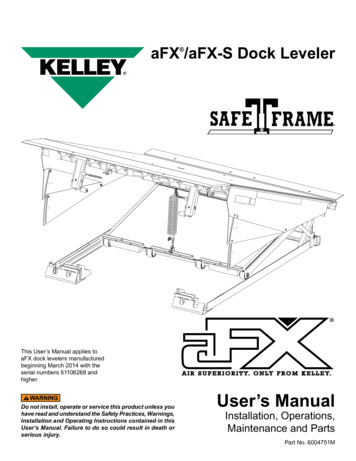
aFX /aFX-S Dock Leveler This User’s Manual applies toaFX dock levelers manufacturedbeginning March 2014 with theserial numbers 61106268 andhigher.Do not install, operate or service this product unless youhave read and understand the Safety Practices, Warnings,Installation and Operating Instructions contained in thisUser’s Manual. Failure to do so could result in death orserious injury.User’s ManualInstallation, Operations,Maintenance and PartsPart No. 6004751M
contentsIntroduction.2Safety Signal Words.2Safety Practices.3Owner’s Responsibilities.4Ramp and Lip Grade.5Installation.6Wiring Diagram.15Operation.16Planned Maintenance.19Service Tools.22Troubleshooting.25Parts List.28Warranty.42Distributor Information.44introductionWelcome and thank you for choosing this dock leveler from Kelley . This dock leveler may be equipped with theoptional ENERGY GUARD dock leveler sealing system.This User’s Manual contains information that you need to safely install, operate and maintain the dock leveler. Italso contains a complete parts list and information about ordering replacement parts. Please keep and read thisUser’s Manual before using your new dock leveler.safety signal wordsYou may find safety signal words such as DANGER, WARNING, or CAUTION throughout this User’s Manual.Their use is explained below:This is the safety alert symbol. It is usedto alert you to potential personal injuryhazards. Obey all safety messages thatfollow this symbol to avoid possible death or injury.Indicates an imminently hazardous situation which, ifnot avoided, will result in death or serious injury.Indicates a potentially hazardous situation which, ifnot avoided may result in minor or moderate injury.Indicates a potentially hazardous situation which,if not avoided, could result in death or seriousinjury.Notice is used to address practices not related topersonal injury.26004751M — aFX and aFX-S Dock Leveler — SafeTFrame 2014 4Front Engineered Solutions, Inc.March 2013
safety practicesRead these Safety Practices before installing, operatingor servicing the dock leveler. Failure to follow the safetypractices could result in death or serious injury.If you do not understand the instructions, ask your supervisorto explain them to you or call your local Kelley distributor.OPERATIONUse restricted to trained operators.Follow procedures on placard posted near dock leveler.Do not use this unit to service vehicles outside its intendedworking range which is 12 inches above and 12 inches belowdock. The working range of 10' dock levelers is 18 inchesabove dock and 12 inches below dock.Visually check that lip is supported by the vehicle platformor the ramp is supported by both dock level supports beforedriving on the ramp.Store dock leveler at dock level after below dock endloading.Ensure lip avoids contact with vehicle sides and cargo. If lipdoes not lower to vehicle bed, reposition vehicle.Do not use a fork truck or other material handling equipmentto lower the ramp.Move all equipment, material or people off dock leveler andstore dock leveler at dock level before allowing the vehicleto leave.INSTALLATION, MAINTENANCE AND SERVICEDo not operate the dock leveler with equipment, material orpeople on the ramp or lip.Place barricades on the dock floor around the dockleveler pit and in the driveway in front of the pit whileinstalling, maintaining or repairing the dock leveler.Do not operate the dock leveler when anyone is in front of itunless they are securing the maintenance strut.Do not operate the dock leveler when anyone is in frontof it unless they are securing the maintenance strut.Stay clear of the dock leveler when it is moving.Prior to placing in the pit, 8' and longer levelers require 6'long forks if handled with a fork lift.Keep hands clear of hinges at all times. Do notuse hands to position dock leveler ramp or lip in vehicle or tostore dock leveler.Stay clear of leveler unless lip supported by the vehicle bedor the ramp is supported by both front dock level supports;unsupported leveler can lower unexpectedly.Do not use the dock leveler if it looks broken or does notseem to work right. Tell your supervisor it needs repair rightaway.Do not stand in the driveway between the dock leveler anda backing vehicle.Before chocking wheels or engaging vehicle restraint, dumpair from air ride suspensions and set parking brakes.Chock vehicle wheels or lock vehicle in place with avehicle restraining device and set brakes before loading orunloading.March 2013PUT AND PIN MAINTENANCE STRUT IN PLACEAND MAKE SURE LIP LOCK IS IN PLACE ANDSUPPORTING THE LIP before climbing into the dockleveler pit or doing any maintenance or repair under thedock leveler.Disconnect the power and properly tag or lock offbefore climbing into the dock leveler pit or doing anymaintenance or repair under the dock leveler.All electrical troubleshooting or repair must be done by aqualified technician and must meet applicable codes.Disconnect the power and properly tag or lock off beforedoing any electrical work.If it is necessary to make troubleshooting checks insidethe control box with the power on, USE EXTREMECAUTION! Do not place fingers or uninsulated toolsinside the control box. Touching wires or other partsinside the control box could result in electrical shock,death or serious injury.6004751M — aFX and aFX-S Dock Leveler — SafeTFrame 2014 4Front Engineered Solutions, Inc.3
owner’s responsibilitiesThe owner’s responsibilities include the following:The owner should recognize the inherent danger of theinterface between dock and transport vehicle. The ownershould, therefore, train and instruct operators in the safe useof dock leveling devices.When a transport vehicle is positioned as closely as practicalto a dock leveling device, there shall be at least 4" of overlapbetween the front edge of the lip and the edge of the floor orsill of the transport vehicle.Nameplates, cautions, instructions and posted warnings shallnot be obscured from the view of operating or maintenancepersonnel for whom such warnings are intended.Manufacturer’s recommended periodic maintenance andinspection procedures in effect at date of shipment shall befollowed and written records of the performance of theseprocedures should be kept.Dock leveling devices that are structurally damaged orhave experienced a sudden loss of support while underload, such as might occur when a transport vehicle is pulledout from under the dock leveling device, shall be removedfrom service, inspected by the manufacturer’s authorizedrepresentative, and repaired as needed before being placedback in service.The owner shall see that all nameplates, caution andinstruction markings or labels are in place and legible andthat the appropriate operating and maintenance manuals areprovided to users.Modifications or alterations of dock leveling devicesshall be made only with written permission of the originalmanufacturer.When industrial vehicles are driven on and off transportvehicles during the loading and unloading operation, thebrakes on the transport vehicle shall be applied and wheelchocks or positive restraints that provide the equivalentprotection of wheel chocks engaged.The dock leveler should never be used outside its verticalworking range or vertical lifting range or outside themanufacturer’s labelled rated capacity. It must also becompatible with the loading equipment and other conditionsrelating to the dock.46004751M — aFX and aFX-S Dock Leveler — SafeTFrame 2014 4Front Engineered Solutions, Inc.March 2013
Ramp and lip gradesFig. 1Ramp gradeLip gradeVEHICLEPLATFORMPOSITION fromDOCK, (in.)ABOVEDOCKRAMP and LIP grades, % for each dock leveler length6' Leveler8' Leveler10' -5.2-6.9-7.54 lip bend, 16" lipMarch 2013VEHICLEPLATFORMPOSITION fromDOCK, (in.)ABOVEDOCKRAMP and LIP grades, % for each dock leveler length6' Leveler8' Leveler10' -4.6-6.3-7.9-17.1-18.8-20.5Optional 7 lip bend, 16" lip6004751M — aFX and aFX-S Dock Leveler — SafeTFrame 2014 4Front Engineered Solutions, Inc.5
installationPIT CHECK1. Check entire dock leveler pit for proper constructionaccording to certified pit drawings (publication 5563 or5566). Check to be sure that the pit walls are squareand plumb. Check electrical service running to the pit toassure it conforms with the correct location and voltagefor the junction box. Inspect the pit and remove allloose trash and construction debris. See the installationtroubleshooting on page 14 if the pit varies from thespecification.leveler check prior to installation1. Visually check that the length of exposed thread on allclamp bar bolts on the airbag are equal to ensure theyare properly tightened.2. Visually check that the 4 rear hinge pins and retainingclips are in place.3. Visually check that the lip shaft collars or shaft retainersare in place on both lip rods.4. Visually check that cotter pins are in place on pins on theconnecting rod, push bar, and the lip lifter assembly.5. Verify that gas spring retaining pins have cotter pinsinstalled.2. Mount and wire push-button control station. See Fig. 2.See wiring diagram on page 15 of this User’s Manual forwiring information. Wires shown in dashed lines are fieldconnections.3. Mount and wire a conduit box with a 120V grounded 515R receptacle on the pit wall as shown in Fig. 3. Wirereceptacle per diagram on page 15.4. If conduit must be installed (replacing an existingmechanical dock leveler) do so at this time. Refer to theconduit requirements on the pit detail publications 5563and 5566 and powered dock leveler wiring diagramsand typical installation drawings, Fig. 3 and powereddock leveler wiring diagram on page 15 for electricalrequirements. Follow all applicable electrical codes andstandards.Before installing the dock leveler, read and follow theSafety Practices on page 3. Failure to follow the SafetyPractices could result in death or serious injury.Fig. 26. Verify that both the lip lock and the maintenance strutare undamaged and have safety hitch pins on chains.48"7. Visually check that the foot assemblies at the rear of theleveler are in place and undamaged.Push-buttoncontrol stationprepare sitePlace barricades around pit on dock floor and drive whileinstalling, maintaining or repairing dock leveler.1. The control station, User’s Manual and dock bumpersare attached to the sub frame of the dock leveler. Themaintenance strut has a plastic tie wrap holding themto the subframe. Remove these items before placingthe leveler into the pit. Make sure the customer gets theuser’s manual and is properly trained.6Fig. 3Pitcenterline 10"12"-13"Box located asshown6004751M — aFX and aFX-S Dock Leveler — SafeTFrame 2014 4Front Engineered Solutions, Inc.March 2013
installation, continuedinstallation of dock leveler6' and 8' long levelers using a standard 19" subframe can befield converted to allow installation in a 24" pit by adding a 4"riser kit, Kelley Part No. 6004652. Install the new riser levelingfeet. The riser blocks should be welded to the front subframesupports and secondary stops prior to placing in the pit. Seepublication #6003727 and page 35 in this manual.Fig. 41. Prior to lifting leveler make sure the shipping tie downbolts seen in Fig. 13 are in place. Install two 3/4"-10UNCload centering eye bolts into the front and rear of the topplate and hoist leveler into pit. The dock leveler shouldnot be lifted in any other manner when place into the pit.See Fig. 4.Inadequate lifting equipment or practices can cause aload to fall unexpectedly. Make sure the lifting chain orother lifting devices are in good condition and have arated capacity of at least 3,500 lbs for the lifting angleused. Never allow anyone to stand on or near the dockleveler when it is lifted or placed into the pit. Stand clearof the dock leveler when it is placed into the pit. Failureto follow this warning can allow the dock leveler to fall,tip, or swing into people, resulting in death or seriousinjury.Route power cord clear of edges and resting surfacesso that it is not damaged during lifting and placement.Plug end may be routed up through the rear hinge untilneeded.3/4" - 10 UNCload centeringeyeboltFig. 5inserting the leveler into the pit2. Position dock leveler in pit about 7" away from therear pit wall. Connect plug to receptacle on the rear pitwall. Cut tie wrap on cord to allow bag pan removal forservice. Place the free length of cord inside of framearea, free of interference as the leveler is moved intothe final position. See Fig. 5 and wiring diagram on page15.NOTE:Check the pit floor for uneven or excess concrete in the areaaround the leveling feet 1"-6" from the rear wall. Use chiselto level out area if necessary.March 20136004751M — aFX and aFX-S Dock Leveler — SafeTFrame 2014 4Front Engineered Solutions, Inc.7
installation, continued3. Move the dock leveler back to the rear pit curb angle.See Fig. 6. With the rear leveler angle touching the rearpit angle, square up the sides of the pit to the sides ofthe leveler. The gap should be even on both sides.Fig. 6NOTE:The rear frame angle should be about 1/2" lower than the pitcurb angle before leveling. This is normal. See Fig. 7.leveling the rear frame4. Using a 1/2" square drive (1/2" ratchet or impact tool)work from one side to the other, turn each of the levelingscrews on the rear angle, counter-clockwise until thetransition angle of the rear angle is level with the rear pitcurb angle and the leveling screws are 1/4" from the toptransition angle which indicates that legs are in contactwith pit floor. Repeat on each leg until the transitionangle is flush with the rear curb angle. See Fig 8.The rear edge of the dock leveler should be level orslightly (1/16" maximum) below dock level.Fig. 7The top surface of the dock leveler should be level and asmooth transition with the dock floor curb steel. The frontend should be level and parallel with the rear frame anglefor proper operation. Unequal adjustment of the frontsupports may be required to obtain a level front edge.1/2"Turn off all electrical power to the leveler if it has beenpreviously connected. Welding with dock levelers powerconnected can damage the electrical components. Aground must be attached to the leveler frame.5. Check and adjust the leveler for square, shim the rearas required, see Fig. 20. The sides of the leveler deckshould be centered in the pit opening. Tack weld the rearangle to rear curb angle in 4 places min 3/8", one at ornear each leveling screw.NOTE:Do not weld out the rear angle until after setting the frontsupports.86004751M — aFX and aFX-S Dock Leveler — SafeTFrame 2014 4Front Engineered Solutions, Inc.March 2013
installation, continuedleveling the FRONT frame6. Remove and discard the shipping tie down bolts locatedat the lower end of the hinged lip assembly. See Fig.13.Fig. 8Transition angleCurbangleRaisesrearangleBefore welding the dock leveler supports to the frontcurb angle make sure that the dock leveler support legsline up with the “V” pocket in the dock leveler supportangle and that the leg roller is centered over the its rollertrack. Move dock levelers support right or left for thenecessary alignment.1/4"7. Tack weld the front dock leveler supports to the front curbangle. See Fig. 12.8. With the lip pendant insert 24" long 1/2" extensionsbetween lip and lip rod onto dock leveler support levelingscrew. See Fig. 12. Using a 1/2" drive (1/2" ratchet orimpact tool) turn each leveling screw counter-clockwiseuntil the top of the leveler is flush with the finished floor/pit curb steel where the overhead door meets the floor.See Fig. 11.finish welding rear frame9. Weld the rear frame angle to the rear curb angle using1/4" bevel joints in the transition angle as your guide.See Fig. 10.Legs are in contactwith pit floor whenthe leveling screwsare 1/4" from thetop of the transitionangleLegadjustmentFig. 9Rear pitcurb angle10. After the rear hinge is welded check that all rear levelinglegs are in contact with the floor of the pit by visuallyinspecting that the leveling screws are 1/4" from the topof the transition angle. Once all legs are in contact withfloor, tighten each leg leveling screw counter-clockwiseto 25-40 ft. lbs.RearframeangleEqual gapRampPit side curb angleFig. 105"2-1/2"5"2-1/2"5"5"March 004751M — aFX and aFX-S Dock Leveler — SafeTFrame Rear hingeassembly 2014 4Front Engineered Solutions, Inc.9
installation, continued11. Lower the air bag lifting support frame by removing theretainer bolts on top of deck area. See Fig. 14. Boltsshould be discarded.Fig. 11Door jambFlush with floor at this pointThe lifting support frame will drop rapidly to the pit floorwhen the retainer bolts are removed. Keep your handsand feet out from under the dock leveler when releasingthe frame. Failure to do so could result in death or seriousinjury.Air pressure or mechanical support must be maintainedunder the ramp to hold it in the raised position until themaintenance strut is in place. DO NOT WORK UNDERTHE DOCK LEVELER RAMP OR LIP UNLESS THEMAINTENANCE STRUT IS IN PLACE AND PINNED, ANDLIP LOCK IS IN PLACE AND SUPPORTING THE LIP.NOTE:The following procedure requires two persons to lockout andsecure the leveler for maintenance.12. Return power to the leveler control. Using the aFXpush-button control or mechanical support, raise thedeck and secure.Fig. 123/16" weld3" long (min.)both sidessecondarystopcurb steel1/2" square drivedock levelersupport levelingscrewa) One person pushes and holds the RAISE buttonto inflate the air bag until the dock leveler reachesits highest position. Hold dock leveler in its highestposition.3/16" weldboth sides3/16" weld3" long (min.)both sidesb) The second person positions the maintenance strutinto the bracket located on the underside of the rampassembly and pins it in place with hairpin clip. SeeFig. 15 and the instruction label on maintenancestrut.c) Air pressure or mechanical support may now beremoved.3/16" weldboth sides3/16" welds3/16" weld3" long (min.)3/16" weldcurb steelFig. 13Shipping tiedown bolt106004751M — aFX and aFX-S Dock Leveler — SafeTFrame 2014 4Front Engineered Solutions, Inc.March 2013
installation, continuedFig. 14Retaining boltsManual support of the lip must be maintained until the liplock is in place. The lip is free to move downward whenit is released unless the lip lock is in position supportingthe lip. DO NOT WORK UNDER THE DOCK LEVELERRAMP OR LIP UNLESS THE MAINTENANCE STRUT IS INPLACE AND PINNED AND LIP LOCK IS IN PLACE ANDSUPPORTING THE LIP.13. To engage lip lock, manually lift lip to fully raised position.Pull lip lock outward as far as it will go. Release lip lock.Slowly lower lip onto lip lock. (See instruction label ondock leveler beam near lip lock.)Fig. 1514. Disconnect power.Insert hairpinclip throughmaintenancestrut pin15. Finish welding both of the adjusted front dock levelersupports in all locations shown in Fig. 12.16. Remove and discard shipping cotter pins from toeguards on both sides of dock leveler. See Fig. 16.LipLiplockMaintenancestrut pinNOTE:6' and 8' long levelers in a 24" pit require the installationof a pan riser kit, part #184389. Install the pan risers. Seepublication #6013529 or #6003727.MaintenancestrutMaintenancestrut bracket17. Remove lifting chain or other lifting devices. Removelifting hooks from the sides of the ramp.18. Read the Safety Practices on page 3, and the OperationInstructions on pages 16 through 18 before operatingthe dock leveler.Fig. 16Removeshipping cotterpinsMarch 20136004751M — aFX and aFX-S Dock Leveler — SafeTFrame 2014 4Front Engineered Solutions, Inc.11
installation, continued22. Two people are needed to store the maintenance strut.Improper installation of anchoring devices or installationinto aged or unsound concrete could result in death orserious injury.The dock face must be flush with curb angle to assureproper bumper mounting.19. Mount dock bumpers to face of dock. Downhill welds areunacceptable. See Fig. 17 or 18.20. Reconnect power. Store maintenance strut and lip lock.Store dock leveler at dock level.a) One person must push and hold the raise buttonuntil dock leveler reaches its highest position andhold dock leveler in its highest position.b) The second person unpins the maintenance strutfrom the bracket on the ramp and stores it on thesubframe. See Fig. 15 and the instruction label onmaintenance strutc) The raise button may now be released. The rampwill lower and the lip will extend when the button isreleased.Fig. 17Manually support the lip when storing the lip lock. Standclear of the lip when removing support. The lip is free tomove downward when support is removed. Anyone in thepath of the lip when it moves downward can be struck.1" Dia.4"3"Keep your hands, fingers and head away from the lipwhen it is released. They could be struck by the lip orcaught between the lip and other parts of the dock levelerresulting in death or serious injury.DO NOT MOVE THE MAINTENANCE STRUT WITHOUTAIR PRESSURE IN THE BAG OR A MECHANICAL LIFTINGDEVICE SUPPORTING RAMP. Raise the ramp using airpressure or a mechanical device before storing themaintenance strut. Stand clear of the ramp and lip whenair pressure or the mechanical lift is applied or removed.The ramp and lip are free to move downward when thesupport is removed. Removing the support without airpressure will allow the ramp and lip to drop RAPIDLY. Ifthe dock leveler was raised using a mechanical device,lower it using the same device.21. Lift lip completely. Push lip lock inward as far as it will go.Slowly lower lip. (See instruction label on dock levelerbeam near lip lock.)MOLDED "L" BUMPERSJ bolts (3) per bumperfurnished by KelleyCompany, Inc. Locateand weld to curbangle at time ofbumper installation.Fig. 18LAMINATED BUMPERS3/8" side of pitto side of bumpermounting plate1/4"Weld full length ofbumper mountingplate. Downhill weldsare unacceptable.Verticalbumpermountingangle126004751M — aFX and aFX-S Dock Leveler — SafeTFrame 2014 4Front Engineered Solutions, Inc.3/4" dia.anchorbolt.fieldinstalled.suppliedby others.To1/4"curbangleLaminations must beinstalled verticallyMarch 2013
installation, continuedFig. 19Warning and operatinginstruction placardThe hinged lip will extend as the ramp moves down.23. Place the dock leveler in both dock leveler storageposition and full below dock end load position. If lip isbeing supported by the curb steel in either position, adeflector plate must be created to allow leveler to storeand reach its full below dock position without gettinghung up on the pit floor.Improper installation that allows the pendant dock levelerlip to support the weight of the dock leveler could resultin death or serious injury. It is sometimes necessary toinstall lip deflector plates to avoid any chance of thependant lip supporting the weight of the dock levelereither near dock level or during a below dock end load.24. Permanently mount the laminated dock leveler placardon the wall near the dock leveler control. See Fig. 19.Make sure the customer gets the User’s Manual and isproperly trained.25. Operate the dock leveler four times through the completecycle to check operation. (See Operation section, page16.)NOTE:If you have any problems or questions using or operatingthe dock leveler, contact your supervisor or local Kelley distributor for assistance.26. Optional (where applicable), install rear angle cap plugs(part number 6004488) into adjustment socket holes.Press cap flush with top surface of rear curb angle.March 20136004751M — aFX and aFX-S Dock Leveler — SafeTFrame 2014 4Front Engineered Solutions, Inc.13
installation, continuedinstallation troubleshootingThe following procedures apply after the leveler is level inthe pit.PROBLEMPOSSIBLE CAUSE1) Leveler will not fit properly in pit.a) Pit is out of square with the sides.a1) Align the sides parallel and equallyspaced with the rear frame angletouching the rear curb angle in oneplace. Fill the gap between the rearcurb angle and rear frame angle usingshims in weld noted in Fig. 10. SeeFig 20.b) One side and rear angle is out ofsquare.b) Align the leveler with the two squareedges. The gap on the sides shouldbe even in the most narrow section(1/2" Max. per side). See Fig. 21.c) Pit floor irregular in rear.c) If large deformations exist in theconcrete work, attempt to flattenout the rough surface using a chiselor grinder to take out the largeobstructions. The rear leveling legscan be installed on out of planesurfaces up to 1/8" at each leg. SeeFig. 22.d) Pit is too deep.d) Weld 4" x 4" shims to the bottom ofthe adjustable legs.Fig. 21Fig. 20SOLUTIONFig. 22Shim and weld flushEqualgap1/2" max.1/8" MAXallowable stepno greater than1" x 3" in size6"contactzone146004751M — aFX and aFX-S Dock Leveler — SafeTFrame 2014 4Front Engineered Solutions, Inc.March 2013
Wiring diagramBefore doing any electrical work, make certain the poweris disconnected and properly tagged or locked off. Allelectrical work must be done by a qualified technicianand meet all applicable codes. If it is necessary to maketroubleshooting checks inside the control box with thepower on, USE EXTREME CAUTION. Do not place yourfingers or non insulated tools inside the control box.Touching wires or other parts inside the control boxcould result in electrical shock, death or serious injury.Never allow more than 130 volts to be connected to the120 volt motor circuit. Damage to motor, push-button, airbag, and serious personal injury or death may result.Fig. 23120V, Single Phase, 50/60 HzSingle ContactControlStationCircuit Breaker(By Others)20 AMP MAX120V1 Phase50/60 HzBLKLineGRNGrnWHTNeutralOptional Blue Contact Block(Normally Closed)Field Installed (Low Voltage Only)See Supplied Mfg. InstructionsControlStationOptional connection to restraintStar4 LA terminals C and 17.For Star4 module with 403 controlleruse 21 and 22To:Circuit Breaker(By Others)20 AMP MAXAuto chock terminal blockterminals no. 5 and no. 24BLKLineGRN MotorGrnWHTNeutralMarch 20131 Phase 120V50/60 HzPit WallReceptacleNEMA 5-15R(By Others)120V, Single Phase, 50/60 HzOptional Dual Contact120V1 Phase50/60 HzMotor1 Phase 120V50/60 HzPit WallReceptacleNEMA 5-15R(By Others)6004751M — aFX and aFX-S Dock Leveler — SafeTFrame 2014 4Front Engineered Solutions, Inc.15
OperationINTRODUCTIONBefore operating the dock leveler, read and follow theSafety Practices on page 3.Use of dock leveler restricted to trained operators. Followprocedures on placard posted near dock leveler.DO NOT USE THE DOCK LEVELER IF IT LOOKS BROKEN,OR DOES NOT SEEM TO WORK RIGHT. Tell yoursupervisor it needs repair right away, or contact yourlocal Kelley distributor.Before pressing button, ensure lip avoids contact withvehicle platform sides and cargo. If lip does not lower tovehicle platform, reposition vehicle platform.Stay clear of leveler unless lip is supported by vehicleplatform or the leveler is stored at dock level. Visuallycheck that the lip is supported by the vehicle platform orthe ramp is supported by both front dock level supportsbefore driving or walking on the ramp. Unsupported docklevelers can lower unexpectedly.Before chocking wheels or engaging vehicle restraint,dump air from air ride suspensions and set parkingbrakes.Always be certain that the vehicle wheels are chocked, orthat the vehicle is locked in place by a vehicle restrainingdevice and the brakes are set before loading or unloading.Vehicles pulling away from the dock unexpectedly cancause uncontrolled drop of the dock leveler which canresult in death or serious injury.This dock leveler is designed to span and compensate forspace and height differences between a loading dock andfreight carrier to allow safe, efficient freight transfers.This dock leveler uses a push-button control to position thedock leveler. Pushing and holding the push-button operatesa fan which inflates an air bag to raise the ramp. Releasingthe push-button allows the ramp to lower.A mechanical linkage extends the dock leveler lip as theramp lowers from its full raised position, and the leveler withits lip extended, settles onto the vehicle platform forming abridge. Patented airDefense sensors glide along reinforcedcams purging stump-out and providing fluid, free-float motionalong with free fall protection in the eve
optional ENERGY GUARD dock leveler sealing system. This User's Manual contains information that you need to safely install, operate and maintain the dock leveler. It also contains a complete parts list and information about ordering replacement parts. Please keep and read this User's Manual before using your new dock leveler.