Transcription
IPMI Configuration GuidePublished December 2018Copyright 2018 ASRock Rack INC. All rights reserved.AST2500 V1.04
TABLE OF CONTENTS1. Introduction. 12. HTML5 Web GUI . 23. Web GUI Overview . 53.1 Menu bar . 53.2 Quick Button and Logged-in User . 63.3 Dashboard . 63.4 Sensor . 73.5 System Information. 93.5.1 System Inventory . 93.5.2 FRU Information . 103.5.3 Power Source. 123.6 Logs & Reports . 123.6.1 IPMI Event Log . 123.6.2 Video Log. 143.7 Settings . 143.7.1 Data & Time . 143.7.2 External User Services . 153.7.2.1 LDAP/E-directory Settings . 163.7.2.2 Active directory Settings . 183.7.2.3 RADIUS Settings . 193.7.3 KVM Mouse Setting . 213.7.4 Log Settings . 223.7.4.1 Log Settings Policy . 223.7.5 Media Redirection Settings . 233.7.5.1 General Settings. 233.7.5.2 VMedia Instance Settings . 253.7.5.3 Remote Session . 263.7.6 Network Settings . 273.7.6.1 Network IP Settings . 273.7.6.2 DNS Configuration . 293.7.7 PAM Order Settings . 303.7.8 Platform Event Filter . 313.7.8.1 Event Filters . 323.7.8.2 Alert Policies . 343.7.8.3 LAN Destinations . 363.7.9 Services . 38
3.7.10 SMTP Settings . 403.7.11 SSL Settings . 413.7.11.1 View SSL certificate . 413.7.11.2 Generate SSL certificate. 423.7.11.3 Upload SSL certificate . 433.7.12 System Firewall. 443.7.12.1 General Firewall Settings . 453.7.12.2 IP Firewall Rules . 463.7.12.3 Port Firewall Rules . 473.7.13 User Management . 493.7.14 Video Recording . 513.7.14.1 Auto Video Settings . 523.7.15 Keep Share NIC Link Up . 543.8 Remote Control . 553.9 Image Redirection . 553.9.1 Remote Media . 553.10 Power Control . 563.11 Miscellaneous . 573.11.1 UID Control . 583.11.2 Post Snoop . 583.12 Maintenance . 593.12.1 Backup Configuration . 593.12.2 Restore Configuration. 593.12.3 Firmware Image Location . 603.12.4 Firmware Update. 613.12.5 BIOS Update. 613.12.6 Restore Factory Defaults . 623.12.7 Reset . 633.13 Sign out . 632
1. IntroductionThe User Guide is for system administrators to remotely access computers with BMC(Baseboard Management Controllers) and IPMI (Intelligence Platform ManagementInterface). System administrators may easily monitor system conditions or manageissues of remote computers via the web-based interface, a web browser on theInternet.Note: All screenshots in this document are provided for illustrative purpose only, and may be differentfrom the actual product.TerminologyAbbreviationADDefinitionActive DirectoryBIOSBasic Input Output SystemBMCBaseboard Management ControllerDHCPDynamic Host Configuration ProtocolDIMMDual-Inline-Memory-ModulesFRUField Replaceable UnitFQDNFully Qualified Domain NameIPMIIntelligent Platform Management InterfaceKVMKeyboard, Video, and MouseLDAPLightweight Directory Access ProtocolMEIntel Management EngineNCSINetwork Controller Sideband InterfaceNTPNetwork Time ProtocolPEFPlatform Event FilterPOSTPower On Self-TestPSUPower Supply UnitRADIUSSELRemote Authentication Dial In User ServiceSystem Event LogSMTPSimple Mail Transfer ProtocolSNMPSimple Network Management ProtocolSSLSecure Sockets LayerTSIGTransaction SignatureVLANVirtual Local Area Network1
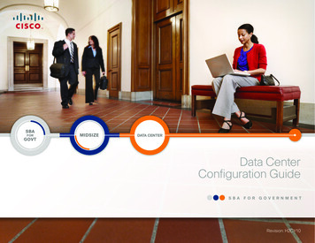
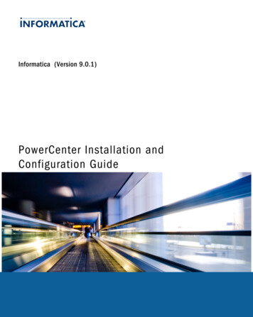
2. HTML5 Web GUILogging in to Web using IPMI userIn order to login the IPMI, you must have a valid Username and a Password. Bothfields are required.Login PageThe default username and password are both “admin”. It is recommended to changethe username and password after your first login.Username: Enter your username in this field.Password: Enter your password in this field.Remember Username: Check this option to remember your login credentials.Sign me in: After entering the required credentials, click the Sign me in to login to WebGUI.I Forgot my Password: If you forget your password, you can generate a new oneusing this link. Enter the username, click on Forgot Password link. This will send thenewly generated password to the configured Email-ID for the user.Language: Select the language of Web GUI, you can choose English, TraditionalChinese or Simplified Chinese.2
Logging in to Web using SSL mutual authenticationYou can also login to the IPMI via SSL mutual authentication without enteringusername/password.Before you login as SSL mutual authentication, ensure that:1. Upload CA certificate(.pem), server certificate(.pem) and server privatekey(.pem) to BMC2. Install the client certificate(.p12) into the browser Chrome: Using “//settings/” to open Manager certificates to import thecertificate. IE11: Using “Tools Internet Options Certificates” to import the certificate. Firefox: Using “Tools Options Advanced Certificates” to import thecertificate.3. Login to IPMI using the link https://[IP address]:[ mutual port number].Note:1.The default mutual port number is 4433. You can modify it in Services page.2.If you want to generate SSL certificate yourself, please follow the steps below. Install OpenSSL in your Linux machine. Generate CA certificate:(1) Type openssl genrsa -out ./private/ca.key 1024 to generate a private key(2) Type openssl req -new -x509 -days 365 -key ./private/ca.key -out ./certs/ca.crt togenerate a certificate file(contain public key)(3) Type cat ./certs/ca.crt ./certs/ca.pem to transfers the file format to .pem. Generate server certificate:(1) Type openssl genrsa -out ./private/server.key 1024 to generate a server key.(2) Type openssl req -new -key ./private/server.key -out ./certs/server.csr to generatethe csr file.(3) Type openssl x509 -req -days 365 -in ./certs/server.csr -CA ./certs/ca.crt-CAkey ./private/ca.key -set serial 01 -out ./certs/server.crt to sign the file andgenerate a server certificate(4) Type cat ./certs/server.crt ./certs/server.pem to transfers the file format to .pem.(5) Type cat ./private/server.key ./private/server key.pem to transfers the file formatto .pem. Generate client certificate:(1) Type openssl genrsa -out ./private/client.key 1024 to generate a client key.(2) Type openssl req -new -key ./private/client.key -out ./certs/client.csr to generate thecsr file.(3) Type openssl x509 -req -days 365 -in ./certs/client.csr -CA ./certs/ca.crt-CAkey ./private/ca.key -set serial 02 -out ./certs/client.crt to sign the file and3
generate server certificate.(4) Type cat ./certs/client.crt ./certs/client.pem to transfers the file format to .pem.(5) Type cat ./private/client.key ./certs/client.pem to export the file. Type openssl pkcs12 -export -in ./certs/client.crt -out ./certs/client.p12 –name "Client Name"-inkey ./private/client.key to transfer client certificate format to p12 for browser.System Requirements Client machine with 8GB RAM.If the client machine has 4GB RAM, there will be lag in Video/keyboard/mousefunctionality.Supported Browsers Chrome latest version.IE11 and above.Firefox (with limited support).Note:1.It is advisable to use Chrome or IE for H5Viewer, since Firefox has its own memory limitations.2.Some icons may not appear on the IE browser screen.3.Once you login to the application, it is recommended not using the following options. Refresh button of the browser Refresh menu of the browser Back and Forward options of the browser F5 on the keyboard Backspace on the keyboard4
3. Web GUI Overview3.1 Menu barThe menu bar displays the following items. Power Status / UID Status Dashboard MiscellaneousSensorSystem InformationLogs & ReportsSettingsRemote ControlImage RedirectionPower ControlMaintenanceSign outMenu bar5
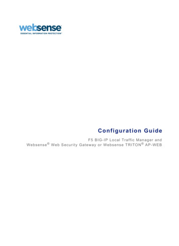
3.2 Quick Button and Logged-in UserThe user information and quick buttons are located at the top right of the Web GUI.Quick Button and User InformationSync: Click the button to synchronize with latest chassis state.Refresh: Click the button to reload the current page.Language: Click the option to change the language (English, Traditional Chinese orSimplified Chinese) for Web GUI.User Information: This option shows the logged-in user name and privilege. ClickProfile to view more information. Click the Sign out to log out of the Web GUI.3.3 DashboardThe Dashboard displays the overall information about the status of the device.Dashboard PageFirmware InformationThe Firmware Information displays the following information.BMC Firmware Version: Displays the BMC firmware version of the device.BIOS Firmware Version: Displays the BIOS firmware version of the device.6
ME Firmware Version: Displays the ME (or PSP) firmware version of the device.Microcode Version: Displays the microcode version of the device.CPLD Version: Displays the version of CPLD of the device.Note:BIOS version, ME (or PSP) version and Microcode version will be refreshed when the system POST,please restart the system if you see nothing on screen.Network InformationThe Network Information of the device with the following fields is shown here. ClickDetails to view more information.MAC Address: Read-only field shows the MAC address of the device.V4 Network Mode: The v4 network mode of the device can be either static or DHCP.IPv4 Address: The IPv4 address of the device can be static or DHCP.V6 Network Mode: The v6 network mode of the device can be either static or DHCP.IPv6 Address: The IPv6 address of the device can be static or DHCP.Sensor MonitoringHere lists all the available sensors on the device with the following information.Status: This column displays the state of the device.- Normal state- Critical State- Not AvailableSensor Name: Displays the name of the sensor.Reading: Displays the value of sensor readings.Event LogsHere displays a graphical representation of all events and occupied/available space inlogs. Click Details to view more information.3.4 SensorThe Sensor Readings page displays all the sensor related information.To open the Sensor Readings page, click Sensor from the menu. Click on any sensorto show more information about that particular sensor, including thresholds and a7
graphical representation of all associated events.Sensor PageIn this Sensor Reading page, Live readings for all the available sensors with details likeSensor Name, Status and Current Reading are shown.Sensor detail:Select a particular Sensor from the Critical Sensor or Normal Sensor lists. The SensorInformation as Thresholds for the selected sensor will be displayed as shown below.Sensor detail Page8
Types of the thresholds: Lower Non-Recoverable (LNR) Lower Critical (LC) Lower Non-Critical (LNC) Upper Non-Recoverable (UNR) Upper Critical (UC) Upper Non-Critical (UNC)3.5 System InformationThis group of pages allows you to view system information.System Information Page3.5.1 System InventoryThis page displays detailed information of active devices. Select a group to view moreinformation.9
System Inventory PageNote:1.The information will be refreshed when the system POST. Please restart the system if you seenothing on screen.2.The information on this page may differ by platforms, and this page may not be available forcertain platforms.3.5.2 FRU InformationThis page displays the FRU information. Select a FRU Device ID from the FRUInformation section to view the details of the selected device.FRU Page10
Available FRU DevicesFRU device ID: Select the device ID from the drop-down list.FRU Device Name: The device name of the selected FRU device.Chassis Information Chassis Information Area Format VersionChassis TypeChassis Part NumberChassis Serial NumberChassis ExtraBoard Information Board Information Area Format VersionLanguageManufacture Date TimeBoard ManufacturerBoard Product NameBoard Serial NumberBoard Part NumberFRU File IDBoard ExtraProduct Information Product Information Area Format VersionLanguageProduct ManufacturerProduct NameProduct Serial NumberProduct VersionProduct Serial NumberAsset TagFRU File IDProduct Extra11
3.5.3 Power SourceThis page displays the PSU information. Please make sure that the PSU supportsPMBus.Power Source PagePower Supply Status: Displays the PSU status is normal or not.AC Input Voltage: Displays the input voltage of the PSU.AC Input Current: Displays the input current of the PSU.DC 12V Output Voltage: Displays the output voltage of the PSU.DC 12V Output Current: Displays the output current of the PSU.Temperature 1: Displays the temperature 1 of the PSU.Temperature 2: Displays the temperature 2 of the PSU.Fan 1: Displays the fan speed 1 of the PSU.Fan 2: Displays the fan speed 2 of the PSU.DC 12V Output Power: Displays the output power of the PSU.AC Input Power: Displays the input power of the PSU.PWS Serial Number: Displays the serial number of the PSU.3.6 Logs & Reports3.6.1 IPMI Event LogThis page displays the list of event logs occurred by the different sensors on thisdevice. Double click on a record to see the details of that entry. You can use thesensor type or sensor name filter options to view those specific events or you can12
also sort the list of entries by clicking on any of the column headers.IPMI Event Log PageFilter By Type: The category can be All Events, System Event Records, OEM EventRecords, BIOS Generated Events, SMI Handler Events, System Management SoftwareEvents, System Software - OEM Events, Remote Console software Events, or TerminalMode Remote Console software Events.Filter By Sensor: Filtering can be done with the sensors mentioned in the list.BMC Timezone: Displays the events with BMC UTC Offset timestamp.Client Timezone: Displays the events with Client UTC Offset timestamp.UTC Offset: Displays the current UTC Offset value based on which event Time Stampswill be updated.Clear MCA Log: To delete MCA log.Download MCA Log: To download the existing MCA log.Clear Event Logs: To delete all the event logs.Download Event Logs: To download all the existing Event Log records as text file.Download Event Logs Raw Data: To download all the existing Event Log records ashex format file.13
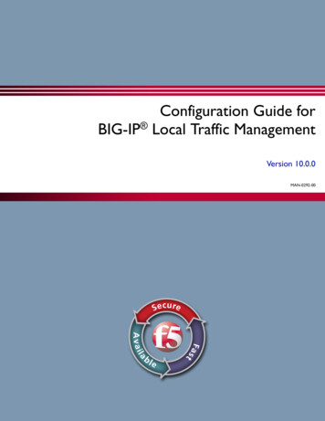
3.6.2 Video LogThis page displays the list of video logs occurred by the different events on thisdevice.Video Log PageFilter By Date: Filtering can be done by selecting Start Date and End Date.3.7 SettingsThis group of pages allows you to access various configuration settings.Settings Page3.7.1 Data & TimeThis page allows administrator to set the date and time on the BMC. It can be used toconfigure either Date & Time or NTP (Network Time Protocol) server settings for thedevice.14
Date & Time PageDate & Time: To specify the current date and time of the device.Timezone: Timezone list contains the UTC offset along with the locations andManual UTC offset for NTP server, which can be used to display the exact local time.Primary NTP Server: To configure a primary NTP server to use when automaticallysetting the date and time.Secondary NTP Server: To configure a secondary NTP server to use whenautomatically setting the date and time.Daylight Saving Time: Enable daylight
2. HTML5 Web GUI Logging in to Web using IPMI user In order to login the IPMI, you must have a