Transcription
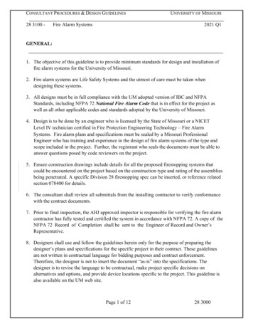
CONSULTANT PROCEDURES & DESIGN GUIDELINES28 3100 -Fire Alarm SystemsUNIVERSITY OF MISSOURI2021 Q1GENERAL:1. The objective of this guideline is to provide minimum standards for design and installation offire alarm systems for the University of Missouri.2. Fire alarm systems are Life Safety Systems and the utmost of care must be taken whendesigning these systems.3. All designs must be in full compliance with the UM adopted version of IBC and NFPAStandards, including NFPA 72 National Fire Alarm Code that is in effect for the project aswell as all other applicable codes and standards adopted by the University of Missouri.4. Design is to be done by an engineer who is licensed by the State of Missouri or a NICETLevel IV technician certified in Fire Protection Engineering Technology – Fire AlarmSystems. Fire alarm plans and specifications must be sealed by a Missouri ProfessionalEngineer who has training and experience in the design of fire alarm systems of the type andscope included in the project. Further, the registrant who seals the documents must be able toanswer questions posed by code reviewers on the project.5. Ensure construction drawings include details for all the proposed firestopping systems thatcould be encountered on the project based on the construction type and rating of the assembliesbeing penetrated. A specific Division 28 firestopping spec can be inserted, or reference relatedsection 078400 for details.6. The consultant shall review all submittals from the installing contractor to verify conformancewith the contract documents.7. Prior to final inspection, the AHJ approved inspector is responsible for verifying the fire alarmcontractor has fully tested and certified the system in accordance with NFPA 72. A copy of theNFPA 72 Record of Completion shall be sent to the Engineer of Record and Owner’sRepresentative.8. Designers shall use and follow the guidelines herein only for the purpose of preparing thedesigner’s plans and specifications for the specific project in their contract. These guidelinesare not written in contractual language for bidding purposes and contract enforcement.Therefore, the designer is not to insert the document “as-is” into the specifications. Thedesigner is to revise the language to be contractual, make project specific decisions onalternatives and options, and provide device locations specific to the project. This guideline isalso available on the UM web site.Page 1 of 1228 3000
CONSULTANT PROCEDURES & DESIGN GUIDELINES28 3100 -UNIVERSITY OF MISSOURIFire Alarm Systems2021 Q19. The Owner’s Representative is the point of contact for the contractor. The local fire departmentwill be contacted ONLY by the Owner representative, unless directed otherwise by theOwner’s representative.Fire alarm symbols and details shall comply with NFPA-170.DESIGN GUIDELINES:1. This design guideline establishes the basic requirements for the design of fire alarm systemsincluding functions, layout, industry standards, permissible systems, and materials.2. Fire alarm system design includes but is not limited to all the following components andsystems:2.1. Fire alarm panel2.2. Initiating devices2.3. Notification devices2.4. Mass notification systems (if desired or required)2.5. Other code required components3. Design calculations shall be done in accordance with NFPA 72 and the followingrequirements:3.1. Current draw on each notification circuit with allowance for 20% expansion.3.2. Voltage drop on each notification circuit.3.3. Stand-by battery capacity for entire system including any power expanders.3.4. Table showing specified device capacity for each addressable loop and thecorresponding number of devices assigned.4. Coordination4.1. Coordination of design is critical to a successful building project. During the designphase of a project, promptly notify architect, structural, civil and electrical engineers ofchanges which affect their work. Coordination should include but is not limited to thefollowing:4.1.1.Confirm location of the remote annunciator with PM. The remote annunciatorwith full capabilities must be provided at the designated fire departmententrance. The PM will confirm this, the location of the main fire alarm panel,knox box, and other alarms with the local fire department.4.1.2.Provide a communication method that satisfies all applicable requirements inChapter 10 of NFPA 72 to communicate alarms to:Page 2 of 1228 3000
CONSULTANT PROCEDURES & DESIGN GUIDELINES28 3100 -Fire Alarm .4.1.5.4.1.6.4.1.7.4.1.8.4.1.9.4.1.10.UNIVERSITY OF MISSOURI2021 Q1UL 3rd party monitoring serviceBuilding Automation System. MU only – Trouble signals to MUCampus Facilities designated representative. UMSL – consult campusPM.Campus Facilities (as instructed by the PM) – by UL 3rd partymonitoring service.Campus Police Building – by UL 3rd party monitoring service.Coordinate with fire protection engineer for locations of flow switches, tamperswitches, fire pumps as well as any other code required components.Coordinate architectural features with Architect including door hold opendevices, door locking devices that must be released by the fire alarm system, orother building related features.Coordinate with the electrical engineer for power needs as well as any otherelectrical devices requiring interconnection with the fire alarm system.Coordinate with the HVAC engineer for connections to air handlers includingsmoke devices and any code required smoke evacuation systems.If a new fire alarm system is being installed in an existing building, the existingfire alarm system shall be maintained fully operational until the new equipmenthas been tested and accepted. If an outage in the fire alarm system is absolutelyneeded, the contractor shall provide a fire watch.Contractor shall include a Fire Watch any time the fire alarm system is takenout of service and must remain out of service. Fire watch shall include aminimum of one person provided by the contractor to perform an hourly tourof the area out of service and provide weekly documentation to the Owner’srepresentative. Documentation shall include the person or persons assigned tothe Fire Watch as well as reporting when rounds were conducted. During theFire Watch any possible fire conditions shall immediately be reported to theCampus Police and to the Owner’s representative. These requirements shouldbe added to the special conditions of the University’s Division 1 documents.The contractor must notify the owner’s representative including any otherparties as specified by the campus. (MU Fire Shop, MU Health Care, local firedepartment, campus police, building coordinator, and others as required.)On existing and new fire alarm systems, the use of a Digital Communicator canbe used provided the DACT unit complies with currently adopted NFPA 72Edition.The campus will contract with a 3rd party monitoring service and will pay allinitial and monthly monitoring fees. The contractor shall notify the owner’srepresentative 60 days in advance of when the digital communicator and thePage 3 of 1228 3000
CONSULTANT PROCEDURES & DESIGN GUIDELINES28 3100 -Fire Alarm SystemsUNIVERSITY OF MISSOURI2021 Q1alarm system will be ready to test so that the owner can arrange for monitoringservice.5. System Requirements5.1. All new fire alarm panels shall be microprocessor based non-coded, addressablesystems.5.2. All new fire alarm panels are to be expandable. Future ability to provide fire alarmservice for entire building or planned building expansion is required. Each notificationcircuit shall contain a minimum of 20% excess capacity. The 20% capacity should be inaddition to the capacity for any planned expansion of the fire alarm or voltage drop.5.3. If a voice system is specified and it is used for other purposes than fire (such as massnotification or broadcasting), comply with NFPA 72 requirements for use of fire alarmsystem for other purposes than fire. For mass notification requirements refer to NFPA72 Emergency Communications Systems sections, as applicable. All device locationsshall comply with ADAAG requirements. Special care will be taken on systems forresidential occupancies.5.4. Wiring systems for both notification and addressable loops is typically Class B. Unlessspecifically required by the University, Class A wiring systems is a design decision,based on an evaluation of site specific conditions and the needs of the facility. MURR,BSL3 labs, hospitals, ambulatory care facilities, high rise, or other high risk facilitiescould require the addressable loop as Class A wiring.5.5. Notification zones5.5.1.These requirements shall include all notification devices such as strobes, horns,or speakers. Multiple circuits may be needed as in the case of speakers andstrobes.5.5.2.At a minimum, each occupied floor shall be on a separate circuit.5.6. Initiation zones5.6.1.Addressable loops shall be designed for reliability. For that reason, the firealarm system will require a minimum of two loops for smaller buildings andadditional loops for larger buildings.5.6.2.Each building shall have one addressable loop per floor to parallel thenotification circuits.5.6.3.The number of fire alarm devices in a loop shall not exceed 20 otherwiseprovide IM (intelligent Module). IM shall be used every 20 fire alarm devices.6. Information Shown on Drawings6.1. Plans shall show all devices required by code including:Page 4 of 1228 3000
CONSULTANT PROCEDURES & DESIGN GUIDELINES28 3100 -Fire Alarm SystemsUNIVERSITY OF MISSOURI2021 Q16.1.1. Alarm Sequence Matrix & Coordination6.1.1.1. Provide a matrix showing alarm and initiation devices by category onone axis and device action on the second axis. An example would be elevatorlobby smoke detector. Actions would be such as general alarm, elevator recall,shut down air handlers, etc.6.1.1.2. Show and specify sequence on air handler shut down. Air handlers shall becontrolled by the FA panel through an addressable relay and not a contact on thesmoke detector.6.1.1.3. Smoke detectors, heat detectors, flow switches, and pull stations activate thegeneral alarm mode unless directed otherwise by the PM and supported by code.For example, duct smoke detectors in facilities monitored by a constantlyattended location, or UL listed supervising station, can initiate a supervisorysignal along with the shutdown of the associated AHU.6.1.2. Alarm Initiation Devices6.1.2.1. Pull stations are required on all occupancies and must be located within 5’ ofeach exit from a floor. Mounting height is to be noted on drawings. Thepreferred mounting height is 48” to the center of the device.6.1.2.2. Smoke and heat detectors are to be shown where required by applicable codes.6.1.2.3. Plans shall clearly show where more than one duct detector is required becauseof duct size.6.1.2.4. Flow switches are to be shown on the fire alarm plan as well as the riser. Thesedevices are to be coordinated with the sprinkler design.6.1.3. Notification Devices6.1.3.1. Notification devices shall be limited to strobes, horns and speakers unlessapproved otherwise by the Project Manager.6.1.3.2. All strobes, horns, speakers, etc. are to be shown on the plans6.1.3.3. The mounting height, candela rating, sound level settings are to be shown onthe drawings. Sound level, candela, or other information that must be set bydevice shall be shown next to the device. Mounting height for strobes, horns,and speakers shall be 80” to the bottom of the device. Where a low ceiling doesnot permit this mounting height, consult NFPA 72 for mounting height andadjustments for coverage. For residence hall sleeping rooms, consult “SleepingArea” tables in Chapter 7 of NFPA 72.6.1.3.4. Spacing of devices is outlined in NFPA 72. Designer must be diligent inshowing spacing for strobes that meet code requirements as well as the soundlevels required for horns and speakers. A note shall be put on the plans toinstruct the contractor to get the approval of the engineer prior to moving anydevice more than 12”. The placement of devices on the plans shall take thisPage 5 of 1228 3000
CONSULTANT PROCEDURES & DESIGN GUIDELINES28 3100 -Fire Alarm SystemsUNIVERSITY OF MISSOURI2021 Q1movement into account when allowing for clearances and code requiredlocations.6.1.4. Supervisory Devices6.1.4.1. Show required supervisory devices including tamper switches, fire pump,engine generator, or other required supervisory signals. Coordinate thelocation of tamper switches and other supervisory devices with the appropriatediscipline.6.1.5. Emergency Control Functions6.1.5.1. All emergency control functions, and their locations shall be shown on thedrawings6.1.5.2. Door hold opens are to be coordinated with the Architect for location andfunction. Provide required smoke detectors where applicable. Hold openscontrolled by addressable relays and may, in some cases, be controlled by othersystems in concert with fire alarm. Designer shall be fully aware of and designcontrol for the functions desired and required by code.6.1.5.3. Door unlocking where desired or required shall be coordinated with otherdisciplines and assure that all applicable egress codes are being followed.Door security (locking) and unlocking functions must be reviewed andapproved by the AHJ.6.1.5.4. Elevator recall shall be done in accordance with the UM adopted versionNFPA 72 and the latest ASME A17.1 elevator code adopted by the State ofMissouri. All work shall be coordinated with other disciplines. Typical recallis as follows and each requires a separate output device on the system.6.1.5.4.1. Elevator recall to designated level6.1.5.4.2. Elevator recall to alternate level6.1.5.4.3. Visual warning for elevator(s) activated by equipment room or hoistwaydevices.6.1.5.4.4. Elevator shutdown initiated by equipment room heat detectors.6.1.6.Expander Panels6.1.6.1. Expander panels should only be used on renovation projects. New buildingsshould use panels and sub-panels that are capable of full coordination andcommunication.6.1.6.2. Where used, expander panels will not be placed above ceilings, in closets orother hard-to-find places. The designer will show the location of allexpander panels clearly on plans.6.1.7.Sub Panels and Annunciators6.1.7.1. Sub panels and annunciators shall be clearly shown on the plans.6.1.8.Riser diagrams are required for the entire system including:Page 6 of 1228 3000
CONSULTANT PROCEDURES & DESIGN GUIDELINES28 3100 -Fire Alarm 1.9.UNIVERSITY OF MISSOURI2021 Q1Notification devices for each and every floor indicating circuiting whichwill correspond with calculations done under paragraph 3 above.Expander panels including notification devices connected to expander paneland sufficient information to verify calculations required in paragraph 3above.Addressable loops showing all initiating devices, supervisory devices andoutput devices on each loop that will correspond to paragraph 3 above. Thisincludes all relays and monitoring devices for air handlers, elevators, firealarm systems, kitchen suppression systems, etc.Sub panels and annunciator panels.Sub panels and annunciators shall be clearly shown on the plans.Power Alarm power supply disconnect, where not in a panel board, shall bepainted red and labeled "FIRE ALARM". Where in a panel board providewith lockable handle or cover and red laminated plate next to breaker withwhite lettering “FIRE ALARM”. Location for power shall not be located incorridors or other public areas. Power disconnect shall be in a secure spaceaccessible only by authorized personnel. All fire alarm equipment as well assupplemental fire equipment shall be placed on dedicated circuits.7. Specifications7.1. All items in this section must be included in the fire alarm specifications.7.2. All devices, equipment and installation are to be provided by a single source who assumesresponsibility for the entire system per NFPA 72. Non addressable devices do not have tobe of the same brand as the main system, but must meet the manufacture’s requirementsand UL ratings for the system installed.7.3. Fire alarm cabinet shall be lockable dead-front, steel enclosure arranged so all operationsrequired for testing or for normal care and maintenance of the system are performed fromthe front of the enclosure. If more than a single unit is required to form a complete controlpanel, provide exactly matching modular unit enclosures. Provide cabinets large enoughto accommodate all components and to allow ample gutter space for interconnection ofpanels as well as field wiring. Identify each enclosure by an engraved red laminatedphenolic resin nameplate. Lettering on the enclosure nameplate shall not be less than 1inch high. Identify individual components and modules within the cabinets by machinelettered signs or labels.7.4. System submittals must include:7.4.1. Power Calculations:7.4.1.1. Battery Capacity Calculations: Battery size shall be a minimum of 125% of thecalculated requirement. Batteries must be capable of operating the panel in normalPage 7 of 1228 3000
CONSULTANT PROCEDURES & DESIGN GUIDELINES28 3100 -Fire Alarm SystemsUNIVERSITY OF MISSOURI2021 Q1mode for 24 hours with sufficient capacity to operate the panel in alarm mode for15 minutes at the end of that 24 hour period.7.4.1.2. Supervisory power requirements for all equipment.7.4.1.3. Alarm power requirements for all equipment.7.4.1.4. Power supply rating justification showing power requirements for each of thesystem power supplies. Power supplies shall be sized to furnish the totalconnected load in a worst case condition.7.4.2. Complete manufacturer's catalog data on all devices, modules, bases, etc.7.4.3. Submit panel and annunciator panel configuration showing layout including thefollowing as applicable:7.4.3.1. Master system CPU including all fire detection, evacuation alarm control modules,and supervised power amplifiers with the required back up modules.7.4.3.2. Circuit interface panels including all modules.7.4.3.3. Power supplies, batteries and battery chargers.7.4.3.4. Pre-amplifiers, amplifiers, and tone generators.7.4.3.5. Equipment enclosures.7.4.3.6. Alarm monitoring modules, and supervised control modules.7.4.3.7. Initiation loop must be capable of supporting at least 60 devices of any type. If theloop supports different numbers of different type devices, it must be capable ofsupporting at least 60 devices of each type.7.4.3.8. Alarm notification circuits must be capable of 1.5 amps per circuit at 24vdc.Panels capable of allowing varying current draws per circuit, but allowing anaverage of 1.5 amps average may be allowed if the engineer designs the circuitsappropriately. In that case each circuit must still have .3 amp minimum allowedfor future in addition to the designed load.7.4.3.9. Wireless systems are not permitted.7.4.4. A complete proposed system database including a description of all logic strings,control by event programming and point identification labels on electronic formatand in a formatted printed form, as required for offsite editing, uploading anddownloading shall be submitted for evaluation by the owner. A programmingmanual shall accompany the submitted program and shall be adequate to allowunderstanding, operation and editing by the system.7.4.5. The latest version of software for programming the fire alarm system. Aprogramming manual shall accompany the submitted program and shall be adequateto allow understanding, operation and editing by the system. At MU, Master firepanel access codes shall be given to the owner.7.5. Specification submittal requirements are to state that proposed vendors must be able toshow the ability to respond to requests for service within 24 hours and the ability to supplyPage 8 of 1228 3000
CONSULTANT PROCEDURES & DESIGN GUIDELINES28 3100 -Fire Alarm SystemsUNIVERSITY OF MISSOURI2021 Q1replacement parts for the system within 48 hours relative to the site where the system is tobe installed.7.6. All fire alarm panels will be equipped with a "walk test" feature. This allows eachactivating device to be tested without the need to reset the panel after each device isactivated.7.7. All fire alarm panels will be equipped with a "building evacuate" switch.7.8. System shall be capable of silencing horns while leaving strobes in alarm. System resetshall reset both horns and strobes. Acknowledge shall silence horns. These functions shallonly be accessible to authorized personnel. This provision may be in conflict with NFPA72, but is accepted as a variance by UM. A trouble alarm shall be indicated in the firealarm panel and in the annunciator panels.7.9. Each circuit, initiating and notification, will have a disconnect switch in the Fire AlarmControl Panel (FACP) to disable the circuit during maintenance. This may be a physicalswitch or a “soft” switch that disables the circuit and causes a trouble on the panel until thecircuit is re-set. The circuit must be disabled and reset by one action of a qualified personwho has access to these switches. These switches are not to be accessible from theoperator portion of the panel but must require the panel to be fully opened to gain access.7.10. If door hold-opens are used, they will be wall-mounted, magnetic type with propermounting blocking in the wall. Combination door closer/hold-opens will not be used.7.11. Initiation Devices7.11.1. All pull stations will be key operated, keyed the same as the building fire alarmpanel. Engineer shall verify key type used by the campus and specify that keytype where the campus has a standard.7.11.2. Infrared detector light source with matching silicon cell receiver. Ionization typesmoke detectors will not be allowed unless directed by the Project Manager.7.11.3. Provide detectors that can be individually monitored at the FACP for calibration,sensitivity, and alarm condition, and have capability of individually adjustablesensitivity from the FACP.7.11.4. Provide visual indication detector has operated.7.11.5. Duct detectors shall be installed with sampling tube properly designed and sizedper manufacturer’s recommendation including an accessible test button. Mountremote indicator (LED) if detector is not visible from the floor. Use White singlegang faceplate labeled: Duct Smoke Detector per NFPA 72.7.11.6. Addressable devices shall not be installed in unconditioned spaces. Fire Alarmdevices mounted outside, such as in parking decks or exterior canopies inloading docks, shall be listed for the location and be installed according to thelisting. The addressable part of the device shall be remotely mounted in aconditioned space. Final location of the remote addressable device shall becoordinated with the Engineer.Page 9 of 1228 3000
CONSULTANT PROCEDURES & DESIGN GUIDELINES28 3100 -Fire Alarm SystemsUNIVERSITY OF MISSOURI2021 Q17.11.7. Proper installation and physical location of each duct detector and access doorsshall be coordinated between the Electrical, Mechanical, and fire alarmsubcontractors, and approved by the Electrical Engineer prior to equipmentinstallation.7.11.8. If new devices or new Fire Alarm Control Panel is added to an existing system,new certification for the existing Fire Alarm Control Panel shall be used inaccordance with NFPA 72 Chapter 14 reacceptance testing requirements. Thisincludes the testing of existing devices as described in the code.7.11.9. The smoke detector in a Handicap accessible room shall also activate the strobefor that room.7.11.10. All detectors or other initiating devices will be installed in locations that arereadily accessible for maintenance. Any initiating device installed above asuspended ceiling (i.e. duct smoke detectors) shall have an indicator showingbelow the ceiling the location of the device. Beam detectors will be used inatriums or other high ceiling areas. Special consideration shall be given if thearea where it is being installed is susceptible to vibrations that may lead to afaulty detector.7.12. Wiring shall be U.L. listed as fire alarm protection signaling circuit cable per NEC.Wire for analog loops will be a minimum of #18 AWG, twisted pair, shielded type FPL,FPLP, FPLR. Wire for notification circuits will be a minimum #14 AWG, type KF-2 orKFF-2. Alarm speaker wire will be a minimum #14 AWG, shielded type CM. Cabletype may vary if recommended by the system manufacturer for compatibility withsystem warranty or design. When a “network” cable is installed between multiple firealarm control units, verify the manufacturer’s wiring requirements and install it in adedicated conduit. No other wires can be installed in that conduit.7.13. All fire alarm system wiring shall be installed in a dedicated raceway. Raceway may beEMT, RMC, FMC, LFMC (flexible type limited by NEC), and surface raceway (only inareas where not subject to damage). Note – For renovation projects where new racewaysmay be difficult or alternatives such as Class A wiring systems could be used to providereliability and/or survivability, a variance to this design guideline may be submitted tothe AHJ. The variance request must include the building occupancy, fire alarm systemdescription, project scope of work, confirmation that all devices are fully addressable,and the justification.7.14. Ground fire alarm equipment, conductors, and cable shields per NFPA and manufacturer.7.15. Notification Appliances7.15.1. Fire alarm horns shall be capable of 10 dBA output higher than NFPArequirement at ten (10) feet. Horns will be Wheelock NH or AH series or equal.Page 10 of 1228 3000
CONSULTANT PROCEDURES & DESIGN GUIDELINES28 3100 -Fire Alarm SystemsUNIVERSITY OF MISSOURI2021 Q17.15.2. Fire alarm strobe flash rate to be one flash per second with low current design.Strobes will be Wheelock RSS series or equal. Strobes with adjustable candelalevels from 15 to 110 shall be specified.7.15.3. Synchronized strobes are required where more than one strobe is visible fromany location, including corridors. Where synchronized strobes are used, useappropriate control module based on manufacturer’s recommendations, such asWheelock SM, DSM or equal.7.15.4. Alarm speakers will be Wheelock series ET or equal.7.15.5. Only speakers or horns will be used unless approved otherwise by the PM inwhich case all code requirements must still be met.7.16. Before partial occupancy, on all fire alarm installations or modification, manufacturershall provide a written satisfactory completion of the required test outlined in NFPA 72.A copy of the NFPA 72 Record of Completion shall be sent to the Engineer of Recordand the Owner’s Rep.7.17. If a new Digital Fire Alarm communicator is included in the project, the system shallmeet the following requirements:7.17.1. The Communicator must be a listed UL product fully compliant with the NFPA72 edition currently adopted and be listed and labeled by an NRTL for use as aSingle Communications Path or in combination with other technologies as aSecondary Communications Path per the code as set forth in Chapter 26. 7.17.2. Supports both dynamic (DHCP) or Public and Private Static IP addressing.7.17.3. Communicates over any type of customer-provided Ethernet 10/100 Basenetwork connection (LAN or WAN), DSL modem or cable modem.7.17.4. Data transmits over standard contact-ID protocol is secured with the industry’sAdvanced Encryption Standard (AES 256 bit).7.17.5. Dual path communications: Uses Internet or GSM as primary. MU – UseInternet7.17.6. User programmable7.17.7. Diagnostic LEDs: Signal strength and status indications.7.17.8. Self-Test: Conducted automatically every 24 hours with report transmitted tocentral station. shall be tested everyday per NFPA 72.7.17.9. All circuits shall be power-limited, per UL864 requirements.7.17.10. Existing and new BAS servers are to be made capable of translating the newcommunicator signals. If unit is connected to an existing non-addressable(conventional) fire alarm system the communicator shall transmit alarm, troubleand supervisory conditions only. Units capable should be considered to providepoint identification of alarms.Page 11 of 1228 3000
CONSULTANT PROCEDURES & DESIGN GUIDELINES28 3100 -Fire Alarm SystemsUNIVERSITY OF MISSOURI2021 Q17.17.11. Battery backup to provide 24 hours of backup in standby and 5 minutes ofalarm operation and battery supervision.7.17.12. Units using cellular communication shall be provided with a local panelmounted antenna and shall also be capable of utilizing a remote high gainantenna if the LTE or greater signal strength is not adequate at thecommunicator location.7.17.13. Each University may prefer to procure and install the digital communicatorunder separate contract. Verify preference with the University PM.Page 12 of 1228 3000
28 3100 - Fire Alarm Systems 2021 Q1 Page 1 of 12 28 3000 . GENERAL: 1. The objective of this guideline is to provide minimum standards for design and installation of fire alarm systems for the University of Missouri. 2. Fire alarm systems are Life Safety Systems and the utmost of care must be taken when designing these systems. 3.
