Transcription
333 Bayview AvenueAmityville, New York 11701For Sales and Repairs, (800) 645-9445For Technical Service, (800) 645-9440 Publicly traded on NASDAQSymbol: NSSCGEM-P801 Control Panel/CommunicatorFor use with the GEM-RP8 or the GEM-K800 KeypadsInstallation InstructionsGEMINIIHEDARMUSTAT1GEMINI234567HSA 1 2 3B 4 5 6JEFC 7 8 9 0 GCOMPUTERIZED SECURITY SY STEMFor use with the GEM-RP8 Keypad NAPCO 2007I8EDARM12345678TUSSTAR 1 2 3B 4 5 6JPQC 7 8 9 0 GCOMPUTERIZED SECURITY SYSTEMFor use with the GEM-K800 KeypadWI1089A 1/07
WI1089A GEM-P801 Installation InstructionsTable of ContentsGeneral Information . 2GEM-P801 Features. 2Specifications . 3UL Compatible Smoke Detectors . 4Listings and Approvals . 4Ordering Information. 4Optional Accessories . 4Programming the Panel . 5Installation . 6Wiring . 6Keypad Operation . 7Panel Operation . 8Bypassing . 9User Program Mode . 9GEM-P801 Commands. 10Dealer Commands . 11Wireless Operation (Signal Strength) . 11Zone Features . 12Test Mode . 12System Times. 13System Features . 14Telephone Number 1 Programming . 16Backup Telephone Programming. 17Pager Programming . 17Telephone Number 3 Programming . 18Report Codes . 18Enhanced Communicator Features . 19SIA CP-01 /Misc. Features .19Wireless . 20Downloading . 21Dealer Programming . 22Download-Only Features . 23SIA CP-01 Quick Reference Chart.25System Troubles . 26Troubleshooting. 28GEM-P801 Wiring Diagram . 30Limited Warranty . 322General InformationThe GEMINI GEM-P801 control panel provides upto 6 hardwired/wireless zones, a 2-wire fire zoneand 2 wireless only zones. Up to eight 4-digituser codes can be programmed. Ambush, whenselected, uses User 8 code as an Ambush code.The GEM-P801 is wireless ready. When usedwith a GEM-RECV-XP8 receiver, the control panelcan support up to 8 wireless zones, 4 wirelesssmoke detectors and 4 Keyfobs.The GEM-K800 keypad provides complete controlof the GEM-P801 control panel. Information onsystem status, bypassed zones, system troublesetc. can be viewed at the keypad.The control panel can be easily and quicklyprogrammed from the keypad. The panel can alsobe locally or remotely downloaded using PCDWindows Version 5.0 or later software and aPCI2000/3000 interface or PCL2000B localDownload cable. See Downloading Section (pg.5) for more information.GEM-P801 FeaturesControl Panel 8 Zones (6 Hardwired/Wireless 2 wireless)2-wire Fire Zone3 Keypad PanicsWireless ReadyBell SupervisionLine Cut DetectionAnswering Machine Override (Second Call)50 Event LogCommunicator 2 Telephone NumbersBackup ReportingPager FormatPoint ID FormatIndividually Report 8 UsersOpening after Alarm Report (Cancel Code)Conditional Closing ReportIMPORTANT NOTE This manual supports keypad programming with both the older GEM-RP8 and the new GEMK800 "K Series" keypad (which offers new STAY / AWAY / MENU and ENTER buttons). While this manual onlydepicts the GEM-K800 keypad buttons, either keypad may be used. Note: For consistency, it is recommendedthat all keypads either be all "classic" or all "K Series"--both keypad types should not be used in one alarm system. Program Mode is the same for both keypads; only the button names have changed, as follows:The A / R buttons and the D / U buttons operate identically (in Program Mode) for both keypads.The E / P ("NEXT / YES") buttons operate identically (in Program Mode) for both keypads.The F / Q ("PRIOR / NO") buttons operate identically (in Program Mode) for both keypads.
SpecificationsLoop CharacteristicsCurrent & Voltage RatingsAlarm Output --------------------------------- Burg:Fire:12 VDC, 2A (max.)12 VDC, 65 mAOutput Current Limiting -------------------- Burg/Fire:AUX Power:2.25 A750 mAResidential Burglary (4 Hour Standby)Combined Standby Current: -------------- 500 mABell Output: ----------------------------------- 2 A(Using Rechargeable 12 VDC 4 AH BATTERY, minimal requirement)Residential Fire (24 Hour Standby)Combined Standby Current: -------------- 120 mABell Output: ----------------------------------- 95 mA§(Using Rechargeable 12 VDC 7 AH BATTERY, minimal requirement)§In NFPA Household Fire Installations, only a single siren orbell can be used on this bell circuit.Transformer and BatteryRequired Transformer: -------------------- NAPCO TRF12 OR BASLER16.5 VAC 20VARequired Battery: --------------------------- 12V 4 AH or 7 AH RechargeableChange Battery every 5 years or as requiredMaximum Charging Current: ------------- 165 mAMaximum Input Current: ------------------- 2.58 ALoop Voltage: -------------------------------- 5 VoltsLoop Current : -------------------------------- 1.1mALoop Resistance: ---------------------------- 300Ω per zone (max.)Device SpecificationsMax # keypads: ------------------------------ 4, GEM-K800/GEM-RP8 current 65 mAMax # of receivers: -------------------------- 2, GEM-RECV-XP8current 65 mA eachMax # of compatible2-wire smoke detectors : ------------------ 10Max Keypad wire length : ---------------- 1000’ total wire lengthMiscellaneousHousing Dimensions : -------------------- 11" x 121/8" x 3"(28 x 30.8 x 7.6) HxWxDShipping Weight: --------------------------- GEM-P801 5.5 lbs.Operating Temperature: ------------------- 0-49ºC (32-120 F)3
WI1089A GEM-P801 Installation InstructionsUL Compatible Smoke DetectorsOrdering InformationGEM-P801 Compatible Smoke Detectors (Approved by UL)MfgSentrol4-WireSmoke 1U742U2112T2112TSRB2-WireSmoke e 2 / OI219WI10908 zone Control Panel with 2-wire Fire(6 Hardwire/Wireless 2 wireless)KeypadOperating Instructions for Keypads GEM-K800 / GEM-RP8Programming Instructions GEM-P801Optional AccessoriesFT2200End of Line Relay/Resistor Supervisory ModuleGEM-RECV-XP8:*Wireless ReceiverGEM-TRANS2:Window/Door TransmitterGEM-KEYF:Keyfob TransmitterGEM-WP:Wireless Waterproof Panic ButtonGEM-SMK:Wireless Smoke DetectorGEM-HEAT:Wireless 135 F / Rate of Rise Heat DetectorGEM-PIR:Wireless PIRGEM-PIRPET:§GEM-DT:Wireless Dual-Technology SensorWireless Pet-Immune PIRLISTINGS AND APPROVALSGEM-GB:Wireless Glass-Break DetectorUL HOUSEHOLD FIRE AND BURGLARY WARNING SYSTEM CONTROL UNITSTANDARDS # 1023, 985.RB1000:§Single Form C Relay BoardVeriphone:§Audio Verification ModuleSECURITY INDUSTRY ASSOCIATION (SIA) FALSE ALARM REDUCTION STANDARD CP-01.PCD-Windows:§Downloading Software for IBM Compatible PCCALIFORNIA STATE FIRE MARSHAL (CSFM) - CONTROL UNIT (HOUSEHOLD) # 71870992:126.VERIFIED TO COMPLY WITH F.C.C. PART 15 AS CLASS B : DIGITAL DEVICE.EUROPEAN E.M.C. REGULATIONS CE CERTIFICATIONHARMONIZED STANDARDS: EN50081-1 AND EN50082-1EC DIRECTIVES: 89/336/EEC, ELECTROMAGNETIC COMPATIBILITY DIRECTIVE4GEM-P801Must be PCD-Windows Version 5.0 or later.PCI2000/3000:§Downloading Interface for IBM Compatible PC (includesPCL2000B Local Download cable)PCL2000B:Local Download cable* Supports up to 8 zones, 4 Key Fobs, 4 Smoke Detectors§Not evaluated by UL.Note: Wireless and Access Features have not been evaluated by UL. Note: Nounattended downloading is allowed by UL.
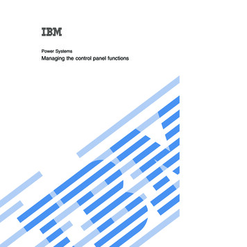
Programming the PanelRefer to GEM-P801 Programming Instructions (WI1090).The GEM-P801 is factory programmed with all features required by the SIA False Alarm Reductionstandard CP-01, and this CP-01 program can bereloaded into the panel by defaulting the panel. Inthis manual and in WI1090, the "†" symbol indicatesthe features that exist in the panel that are specifically required by CP-01.Note: The communicator features are enabled butrequire a telephone number, account number, correct reporting format and report codes (if required bythe format) or the panel will generate a "fail to communicate" trouble. If the panel is intended for localuse, only remove the 1 from programming location[45-1] to disable the communicator.DownloadingThe GEM-P801 panel can be download/uploadedwith PCD-Windows Version 5.0 (or later) softwareusing the Ring Method, Answering MachineOverride (Second Call) or the Keypad ConnectR6 method of downloading. The panel canalso be automatically downloaded/uploaded usingthe PCPreset utilty. For Site Initiated Downloaded,see Auto Download ID Number [93].Note: Any programming in Dealer Options 1 [96] and DealerOptions 2 [97] will not be defaulted. If Dealer Code Lockout hasbeen programmed the panel will not default the Dealer Code.Note: Unattended downloading from a computer is notallowed for Fire Alarm or UL installations.Local DownloadingWire as shown in Figure 1. Use the power up orR6 method of establishing a connection. Thepower up method is recommended if the panel is attemptingto report.TELCO JACKRJ31XTELCOJACKDefaulting the Panel1. Remove power from the panel.2. Remove all wiring from terminal 19 (PGM) andterminal 3.3. Connect terminal 19 (PGM) to terminal 3.4. Apply power to the GEM-P801 control panel.5. After a few seconds the ARMED, READY andHSYSTEM TROUBLE LEDs will flash.6. The keypad will beep 3 times indicating thepanel default values have been loaded.7. Turn off power and remove wiring betweenterminal 19 (PGM) and terminal 3.8. Re-install original wiring for terminal 19 (PGM)and terminal 3 then re-apply power.1. The Keypad Connect R6 method2. Ring method3. Answering Machine Override (Second Call)4. Site-Initiated (PCPreset & R6)5. Automatic Downloading (Using PCPreset)GEM-P801 Panel at the site1617 e if not usedPCL2000BJ1J2TO COMPUTERTO EXTERNALMODEMJ3LOCALTOJ5 LINEOUT TOJ4TELCOMODEMFIGUREDownloading1 LOCAL DOWNLOADRemoteWire as shown in Figure 2. The panel can beremotely download/uploaded using any one of thefollowing methods:MODEMFIGURE 1 REMOTE DOWNLOAD5
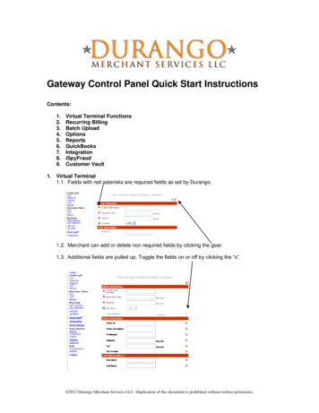
WI1089A GEM-P801 Installation InstructionsInstallationMounting the PanelMount the Panel close to an unswitched ACsource, a cold-water pipe ground, and atelephone line connection.Mounting the KeypadA keypad should be located near an exit/entrydoor. To remove the keypad from the backplate,insert a small screwdriver into the slots at thebottom of the keypad.Pull up on thescrewdriver to pop off the cover.detectors should be installed in areas other thanthose required, such as the dining room,bedrooms and utility room. Heat detectors,rather than smoke detectors, are recommendedin kitchens, attics, and garages due toconditions that may result in false alarms andimproper operation.Refer to NFPA Standard 74 (National FireProtection Association, Batterymarch Park,Quincy, MA 02269) for additional information,including proper mounting methods.12 ( PWR)BLACK13 (GND)GREEN14 (GREEN)Telephone WiringWire as shown in the wiring diagram in the backof this manual.WARNINGThe FCC restricts the use of this equipment oncertain telephone lines.Read the FCCstatement on the back of this manual to ensurecompliance.TABLE 1 KEYPAD W IRINGTypical Fire Installation(Where permitted by local codes)Install smoke detectors outside each sleepingarea and on each floor, including the basement.Install the living room and basement smokedetectors near the stairway of the next upperlevel.For increased protection, additional6Connect the control-panel EARTH GROUNDscrew through a No. 16 AWG or larger wire to ametal cold-water pipe. Do not use a gas pipe,plastic pipe or AC ground connections. Use atleast #16 AWG wire. Connect a wire with aground lug crimped or soldered onto one endand connect it to the EARTH GROUND screw inthe cabinet.Complete all wiring before connecting thebattery or AC Power.Do not plug thetransformer into a switched outlet.Control Panel TerminalREDGrounding the PanelAC Power and Battery WiringUp to 4 keypads can be connected on individualwire runs with #22 AWG wire with a maximumtotal cable length of 1000 feet. Each keypaddraws approximately 65 mA.Keypad Wire ColorWiringFIGURE 3 Typical Fire Installation
Burglary Zone WiringFire Zone WiringThe GEM-P801 provides 6 true hard-wired, EndOf-Line Resistor terminated burglary zones.Wire zones as shown in the wiring diagram (pg.30). All resistors must be installed, even if thezone is not used. If required, the feature NoEnd Of Line Resistor may be programmed, inwhich case a direct short across the zone willcause the zone to set up. (NOTE: Not for ULapplications) Program the zone as a No EOLResistor Zone [06].If necessary, use the voltage chart below toverify proper voltages. These values representthe DC voltage of the zone while in the indicatedstate with reference to the the zone’s respectiveground terminal.Zone Normal (EOL across zone)2.5 VZone shorted0VZone Open5VTABLE 3 VOLTAGE AT TERMINALS 3&5, 6&8,Wire the Fire Zone as shown in the WiringDiagram in the back of this manual. An EOLresistor must be installed, even if the Fire Zoneis not used.Fire Zone Normal13.0VFire Trouble13.8VFire0.0 VTABLE 4 VOLTAGE AT FIRE ZONE (Terminals12&13)PGM WiringThe PGM (Terminal 19) is a switched negativeoutput that is activated through programmingoption(s) that have been selected inprogramming blocks [08], [23] - [25]. Connectthe device controlled by the PGM between PWR and the PGM terminal. (maximum load of50 mA).The PGM output is limited on the number offeatures that can be programmed simultaneously, such as PGM Access.9&11Keypad OperationKeypad zone LEDs indicate zone status.ARMED, STATUS and HSYSTEM LEDsKeypad Sounder3 QUICK BEEPSPanel Armed (System ON)Chime ONFault Find Mode ONKeypad Sounder ONZone Bypassed6 QUICK BEEPSPanel Disarmed (System OFF)Chime OFFFault Find Mode OFFKeypad Sounder OFFZone Un-Bypassed1 SECOND - STEADY TONEIncorrect Code EnteredInvalid key entry4 LONG BEEPS (PRIORITY CONDITION)1. Entering an Arm Code with a faulted zone(Not an Auto-Bypass Reentry Zone).2. Entering an Arm Code when the Bell orPGM is ON (Bell and PGM will turn OFF).3. Arming with the Fire LED ON - resetrequired. Press the C key.provide system status. The keypad sounderprovides feedback beeps for correct andincorrect entries.7
WI1089A GEM-P801 Installation InstructionsPanel OperationKeypad LEDsARMED LED DEFINITIONArmedInstant ModeZone in AlarmSTATUS LED DEFINITIONReady to be ArmedZone faultedHONOFFFlashingONFIRE LED DEFINITIONFire AlarmFire MemoryFlashingONAC LED DEFINITIONAC PresentAC FailureONOFFZONE LED DEFINITIONFaulted ZoneBypassed ZoneZone in Alarm8ONRapid FlashFlashingTROUBLE LED DEFINITIONAC FailureSystem Trouble(s)IArming (System ON)ONSlow FlashFlashingBefore arming the system close all protectedzones (unless programmed as Auto-BypassReentry Zones). Enter a 4-digit Arm/Disarmcode, followed by theUkey, the keypad willprovide a feedback beep for each key pressed.If a valid Arm/Disarm code is entered, thekeypad will beep 3 times. If an incorrect Arm/Disarm code is entered, the keypad will sound a1-second tone indicating an incorrect entry.Arming without Entry Delay (InstantMode)When arming, press the P key to eliminatethe entry delay. The ARMED LED will flashrapidly to indicate the panel is in Instant Mode.If an Exit/Entry Zone is tripped while the panel isin Instant Mode the panel will go into alarmimmediately.Arming/Disarming with a KeyfobThe system can be armed by pressing the Kkey, and disarmed by pressing the L key onthe Keyfob. Zones programmed as Exit/EntryFollower Zones can be bypassed when the Mor N keys on the Keyfob [81-84] have beenprogrammed for Interior [8].Zonesprogrammed as Exit/Entry Follower Zones canbe un-bypassed when the M or N keys onthe Keyfob have been programmed for Full SetSystem [7]. To arm the system with all zonesprotected press the K key. Press and holdthe M or N key for 2 seconds to fully set thesystem (The LED on the Keyfob indicate theKeyfob has transmitted the signal). ProgramKeyfob/Keyswitch Chirp [23-4] for an audibleindication of system arming and disarming.Arming/Disarming with a KeyswitchThe system can be armed/disarmed by using amomentary Keyswitch [26-1] and wired to Zone6 in series with resistor with a normally closedswitch. Program Keyfob/Keyswitch Chirp [23-4]for an audible indication of system arming anddisarming. To convert keyswitch operation fromNormally Closed style to Normally Open,program [27-1] Keyswitch Polarity.NOTE:Faulted Keyswitch or silent 24 hour zone normally do not display atthe keypad. If a silent 24 hour zone or Keyswitch is faulted at thetime of arming the faulted zone will display only while the prioritysound is ON. Keyswitch Arm with No End of Line Resistor programmed; must program [06-6] No End-of-Line Resistor for Keyswitch Zone 6 and must not program [27-1] Keyswitch Polarity.Arming Instant with a KeyfobThe panel can be ARMED INSTANT when the[A1] or [A2] keys on the Keyfob [81-84] havebeen programmed for Instant [8]. To arm thesystem with Instant protection press the [ON]key, then press and hold the [A1] or [A2] key for2 seconds to arm the panel with INSTANTprotection.
Disarming (System OFF)After entering the premises through an Exit/Entry Zone, the keypad will sound the EntryDelay Tone. Enter a valid Arm/Disarm code,then pressU.If a valid Arm/Disarm code isentered, the keypad will beep 6 times, indicatingthe panel has been disarmed. The red ArmedLED will go out. If an incorrect Arm/DisarmCode is entered, the keypad will sound a 1second tone, indicating incorrect entry. PressC and re-enter the code.Disarming after an Alarm (Alarm Memory)The armed LED and the zone(s) that caused thealarm will be be flashing. Disarm the panel.The system is currently not detecting zone faultsor displaying system trouble. The zone(s) thatcaused the alarm will continue to flash. TheSTATUS and HSYSTEM TRBL LEDs are outindicating:The system is displaying Alarm Memory.Press C to clear Alarm Memory.BypassingAutomatic BypassingNote: Automatic Bypassing has not beenevaluated by ULHome/Away with Delay ZonesThis zone type has the following operationdepending on whether an Exit/Entry Zone hasbeen violated during the Exit Delay time.HomeExit/Entry Zone is not violatedZones selected as Home/Away with DelayZones will be bypassed automatically.Away with DelayExit/Entry Zone is violatedZones selected as Home/Away with DelayZones will have a fixed 20-second entrydelay when violated before an Exit/EntryZone.Return to FULL SET SYSTEM (no interiors bypassed) after having been FullSet System with Home/Away with Delay(N
ul household fire and burglary warning system control unit standards # 1023, 985. security industry association (sia) false alarm reduction standard cp-01. california state fire marshal (csfm) - control unit (household) # 7187-0992:126. verified to comply with f.c.c. part 15 as class b : dig