Transcription
Power SystemsManaging the control panel functions
Power SystemsManaging the control panel functions
NoteBefore using this information and the product it supports, read the information in “Notices,” onpage 21, “Safety notices” on page v, the IBM Systems Safety Notices manual, G229-9054, and theIBM Environmental Notices and User Guide, Z125–5823.This edition applies to IBM Power Systems servers that contain the POWER6 processor and to all associatedmodels. Copyright IBM Corporation 2007, 2009.US Government Users Restricted Rights – Use, duplication or disclosure restricted by GSA ADP Schedule Contractwith IBM Corp.
ContentsSafety notices . . . . . . . . . . . . . . . . . . . . . . . . . . . . . . . . . vManaging the control panel functions . . . . . . . . . . . . . . . . . . . . . . . 1What's new in Managing the control panel functions . . . . . . . . . . . . . . . .Control panel concepts . . . . . . . . . . . . . . . . . . . . . . . . . .Physical control panel . . . . . . . . . . . . . . . . . . . . . . . . .Accessing the control panel functions using the physical control panel . . . . . . . . .Putting the physical control panel in manual operating mode . . . . . . . . . . . .Control panel function codes . . . . . . . . . . . . . . . . . . . . . . . .Primary control panel functions . . . . . . . . . . . . . . . . . . . . . . .Function 01: Display selected IPL type, system operating mode, and IPL speed . . . . . .Function 02: Select IPL type, IPL speed override, system operating mode, and firmware mode .Function 03: Restart IPL . . . . . . . . . . . . . . . . . . . . . . . .Function 04: Lamp test . . . . . . . . . . . . . . . . . . . . . . . . .Functions 05 - 06: Reserved . . . . . . . . . . . . . . . . . . . . . . .Function 07: SPCN functions . . . . . . . . . . . . . . . . . . . . . . .Function 08: Fast power off . . . . . . . . . . . . . . . . . . . . . . .Functions 09 - 10: Reserved . . . . . . . . . . . . . . . . . . . . . . .Function 11: SRC display (ASCII string) . . . . . . . . . . . . . . . . . . .Function 12: SRC display (hex words 2 - 5) . . . . . . . . . . . . . . . . . .Function 13: SRC display (hex words 6 - 9) . . . . . . . . . . . . . . . . . .Functions 14 - 19: SRC display (callouts) . . . . . . . . . . . . . . . . . . .Function 20: System type, model, feature code, and IPL type . . . . . . . . . . . .Customer-extended panel functions . . . . . . . . . . . . . . . . . . . . .Function 21: Service tool initiation . . . . . . . . . . . . . . . . . . . . .Function 22: Partition dump . . . . . . . . . . . . . . . . . . . . . . .Functions 23 - 24: Reserved . . . . . . . . . . . . . . . . . . . . . . .Functions 25 - 26: Service switches 1 and 2 . . . . . . . . . . . . . . . . . .Functions 27 - 29: Reserved . . . . . . . . . . . . . . . . . . . . . . .Function 30: Service processor IP address and port location . . . . . . . . . . . .Functions 31 - 33: Reserved . . . . . . . . . . . . . . . . . . . . . . .Function 34: Retry partition dump. . . . . . . . . . . . . . . . . . . . .Functions 35 - 41: Reserved . . . . . . . . . . . . . . . . . . . . . . .Function 42: Platform dump . . . . . . . . . . . . . . . . . . . . . . .Function 43: Service processor dump . . . . . . . . . . . . . . . . . . . .Functions 44 - 54: Reserved . . . . . . . . . . . . . . . . . . . . . . .Function 55: View and change platform dump data . . . . . . . . . . . . . . .Functions 56 - 62: Reserved . . . . . . . . . . . . . . . . . . . . . . .Function 63: Display system status SRCs . . . . . . . . . . . . . . . . . .Function 64: Display diagnostic status SRCs . . . . . . . . . . . . . . . . .Functions 65 - 70: Not applicable . . . . . . . . . . . . . . . . . . . . .Functions 71 - 99: Reserved . . . . . . . . . . . . . . . . . . . . . . .Values for IPL types, system operating modes, and speeds . . . . . . . . . . . . . 1. 1. 1. 3. 3. 3. 5. 5. 6. 8. 8. 8. 9. 10. 10. 10. 10. 11. 11. 12. 12. 12. 12. 13. 13. 13. 13. 14. 14. 14. 14. 14. 15. 15. 16. 16. 17. 17. 17. 18Appendix. Notices . . . . . . . . . . . . . . . . . . . . . . . . . . . . . . . 21Trademarks . . . . .Electronic emission noticesClass A Notices . . .Terms and conditions . . Copyright IBM Corp. 2007, 2009.22222226iii
ivPower Systems: Managing the control panel functions
Safety noticesSafety notices may be printed throughout this guide:v DANGER notices call attention to a situation that is potentially lethal or extremely hazardous topeople.v CAUTION notices call attention to a situation that is potentially hazardous to people because of someexisting condition.v Attention notices call attention to the possibility of damage to a program, device, system, or data.World Trade safety informationSeveral countries require the safety information contained in product publications to be presented in theirnational languages. If this requirement applies to your country, a safety information booklet is includedin the publications package shipped with the product. The booklet contains the safety information inyour national language with references to the U.S. English source. Before using a U.S. English publicationto install, operate, or service this product, you must first become familiar with the related safetyinformation in the booklet. You should also refer to the booklet any time you do not clearly understandany safety information in the U.S. English publications.German safety informationDas Produkt ist nicht für den Einsatz an Bildschirmarbeitsplätzen im Sinne § 2 derBildschirmarbeitsverordnung geeignet.Laser safety informationIBM servers can use I/O cards or features that are fiber-optic based and that utilize lasers or LEDs.Laser complianceAll lasers are certified in the U.S. to conform to the requirements of DHHS 21 CFR Subchapter J for class1 laser products. Outside the U.S., they are certified to be in compliance with IEC 60825 as a class 1 laserproduct. Consult the label on each part for laser certification numbers and approval information.CAUTION:This product might contain one or more of the following devices: CD-ROM drive, DVD-ROM drive,DVD-RAM drive, or laser module, which are Class 1 laser products. Note the following information:v Do not remove the covers. Removing the covers of the laser product could result in exposure tohazardous laser radiation. There are no serviceable parts inside the device.v Use of the controls or adjustments or performance of procedures other than those specified hereinmight result in hazardous radiation exposure.(C026)CAUTION:Data processing environments can contain equipment transmitting on system links with laser modulesthat operate at greater than Class 1 power levels. For this reason, never look into the end of an opticalfiber cable or open receptacle. (C027)CAUTION:This product contains a Class 1M laser. Do not view directly with optical instruments. (C028) Copyright IBM Corp. 2007, 2009v
CAUTION:Some laser products contain an embedded Class 3A or Class 3B laser diode. Note the followinginformation: laser radiation when open. Do not stare into the beam, do not view directly with opticalinstruments, and avoid direct exposure to the beam. (C030)Power and cabling information for NEBS (Network Equipment-Building System)GR-1089-COREThe following comments apply to the IBM servers that have been designated as conforming to NEBS(Network Equipment-Building System) GR-1089-CORE:The equipment is suitable for installation in the following:v Network telecommunications facilitiesv Locations where the NEC (National Electrical Code) appliesThe intrabuilding ports of this equipment are suitable for connection to intrabuilding or unexposedwiring or cabling only. The intrabuilding ports of this equipment must not be metallically connected to theinterfaces that connect to the OSP (outside plant) or its wiring. These interfaces are designed for use asintrabuilding interfaces only (Type 2 or Type 4 ports as described in GR-1089-CORE) and require isolationfrom the exposed OSP cabling. The addition of primary protectors is not sufficient protection to connectthese interfaces metallically to OSP wiring.Note: All Ethernet cables must be shielded and grounded at both ends.The ac-powered system does not require the use of an external surge protection device (SPD).The dc-powered system employs an isolated DC return (DC-I) design. The DC battery return terminalshall not be connected to the chassis or frame ground.viPower Systems: Managing the control panel functions
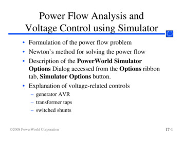
Managing the control panel functionsThe control panel functions allow you to interface with the server. Control panel functions range incomplexity from functions that display status (such as IPL speed) to service functions that only servicerepresentatives must access.What's new in Managing the control panel functionsRead about new or significantly changed information in Managing the control panel functions since theprevious update of this topic collection.October 2009Miscellaneous changes have been made throughout the information.Control panel conceptsLearn about the control panel functions, IPL modes and values, and other concepts.Physical control panelThe physical control panel is your initial interface with the server. You can use the physical control panelto perform functions such as IPL, power on, and power off.Figure 1. 570 control panelv A: Power-on buttonv B: On/off power symbolv C: Serial number labelv D: Function/Data displayv E: System port (S1)v F: Power LED– A blinking light indicates standby power to the unit.– A constant light indicates full system power to the unit. Copyright IBM Corp. 2007, 20091
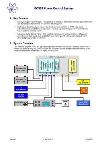
Note: There is approximately a 30-second transition period from the time the power-on button ispressed to when the power LED goes from blinking to solid. During the transition period, you mightobserve the blinking intervals speed up.v G: Decrement buttonv H: Enter buttonv I: Increment buttonThe system attention light is located along the upper right edge of the first drawer.Figure 2. Control panel for the 8203-E4A, 8204-E8A, 9407-M15,9408-M25, and 9409-M50.v A: Power-on buttonv B: Power LED– A blinking light indicates standby power to the unit.– A constant light indicates full system power to the unit.Note: There is approximately a 30-second transition period from the time the power-on button ispressed to when the power LED goes from blinking to solid. During the transition period, you mightobserve the blinking intervals speed up.vvvvvvv2C: Attention lightD: USB portE: Pinhole reset buttonF: Function/Data displayG: Decrement buttonH: Enter buttonI: Increment buttonPower Systems: Managing the control panel functions
Accessing the control panel functions using the physical control panelThe control panel functions correspond to function numbers on the control panel.To activate a control panel function, do the following:1. Select a function number by pressing the Increment ( ) or Decrement ( ) button on the control panel.2. To activate the function, press Enter on the control panel.Putting the physical control panel in manual operating modeYou must first put the physical control panel in manual operating mode before you can select or activatecertain functions.To put the physical control panel in manual operating mode, do the following:1. Use the Increment button to scroll to function 02.0 22. Press Enter to start function 02.3. Press Enter again to move to the second character on the function 02 menu. The current systemoperating mode is displayed with a pointer, as shown in the following example:0 2 B N P4. Use the Increment button to scroll through the system operating modes, and select M for manual, asshown in the following example:0 2 B M P5. Press Enter to select the system operating mode.6. Press Enter again to exit function 02.The control panel is in manual operating mode.Related reference“Function 02: Select IPL type, IPL speed override, system operating mode, and firmware mode” on page6This function allows you to select the IPL type and logical key mode when the system is either poweredon or off.Control panel function codesLearn about function codes that are displayed on the control panel to indicate status and functionoptions.To display all functions, put the control panel in manual operating mode. For details, see Putting thephysical control panel in manual operating mode.The following table includes descriptions of the primary and customer-extended control panel functioncodes.Table 1. Primary and customer-extended control panel (32-character) function codesFunction codeFunction selected01Displays the current IPL parameters.This function is available in both normal and manual operating mode.02Used to select the IPL type, system operating mode, IPL speed, and firmware IPLmode. This function is available in both normal and manual operating mode.Managing the control panel functions3
Table 1. Primary and customer-extended control panel (32-character) function codes (continued)Function codeFunction selected03Restarts an IPL of the system using the selected IPL parameters. This function isavailable only in manual operating mode and when the system power is on.04Performs a lamp test; all displays and indicators are lit. This function is availablein both normal and manual operating mode.05 - 06Reserved.07Allows you to perform SPCN service functions. This function is available only inthe manual operating mode and from power on standby.08Causes a fast power off. This function is available only when the system is inmanual operating mode and the system power is on.09 - 10Reserved.11Displays a system reference code (SRC) on the control panel using up to 32 ASCIIcharacters, including non-hexadecimal characters. This function is available in bothnormal and manual operating mode when an SRC is available.12Displays an SRC on the control panel using up to four extended SRC data words.This function is available in both normal and manual operating mode when anSRC is available.13Displays an SRC on the control panel using up to eight extended SRC data words.This function is available in both normal and manual operating mode when anSRC is available.14 - 19Displays an SRC on the control panel using callout data. These functions areavailable in both normal and manual operating mode when an SRC is available.20Displays the machine type and model, VPD card CCIN, and IPL types. Thisfunction is available in both normal and manual operating mode.21For System i models, it causes the Use Dedicated Service Tool (DST) display toappear on the system console. To exit the DST, select the Resume operatingsystem display option. This function is available only in the manual operatingmode and when activated by the IBM i operating system.Not applicable forSystem p servers.22Forces a partition dump. For more information on dumps, see Performing dumps.This function is available only in the manual operating mode and when activatedby the operating system.23 - 24Reserved.25 - 26Use service switches 1 and 2 to enable or disable functions 50 through 99. Thesefunctions are available only in the manual operating mode.27 - 29Reserved.30Displays the service processor IP address and port location. This function isavailable only in the manual operating mode and in standby.Note: If IPv6 is displayed, then the service processor's network ports areconfigured with IPv6 IP addresses. There are not enough characters on the controlpanel to display the entire address.31 - 33Reserved.34For System i models, it retries the partition dump. This function is available onlyin the manual operating mode and when activated by the IBM i operatingsystem.Not applicable for System p servers.35 - 41Reserved.42Performs a platform dump. This function is available only in the manualoperating mode and when activated by the operating system or the serviceprocessor.4Power Systems: Managing the control panel functions
Table 1. Primary and customer-extended control panel (32-character) function codes (continued)Function codeFunction selected43Performs a service processor dump. This function is available only in the manualoperating mode.44 - 54Reserved.55Displays or changes the platform dump collection policy, platform dumphardware content, and platform dump firmware content settings. This function isavailable only in the manual operating mode.56 - 62Reserved.63Displays up to the last 25 system status SRCs. This function is available only inthe manual operation mode.64Displays up to the last 25 diagnostic status SRCs. This function is available only inthe manual operation mode.65 - 70Not applicable.71 - 99Reserved.If you cannot find the function code in this chart, added features or devices might not have beenavailable when this information was produced. Look on the control panel for supplemental unit functioncode information for the function code that you displayed.Related tasks“Putting the physical control panel in manual operating mode” on page 3You must first put the physical control panel in manual operating mode before you can select or activatecertain functions.Primary control panel functionsThe primary control panel functions, include displaying the selected IPL type, selecting the firmwaremode, or restarting an IPL.Function 01: Display selected IPL type, system operating mode, andIPL speedThis function allows you to display the current system operating mode, the IPL speed for the next IPL,the firmware mode for the next IPL, and the operating system IPL mode (when enabled).This function is available in both normal and manual operating mode.This function displays the following information:vvvvTheTheTheTheoperating system (OS) IPL types (A, B, C, or D).valid logical key modes (M or N).IPL speed (F, V F, S, V S, H, V H, X, or V X).firmware mode (P or T).Table 2. Function 01 on systems without OS IPL enabledFunction/DataAction or description0 1Use the Increment or Decrement buttons to scroll to function01.Managing the control panel functions5
Table 2. Function 01 on systems without OS IPL enabled (continued)Function/DataAction or description0 1 A M V FPValid OS IPL types are A, B, C, and D.Valid system operating modes are M and N.Valid IPL speed displays are F, V F, S, V S, H, and V H.Valid firmware IPL modes are P and T.0 1Use the Increment or Decrement buttons to scroll throughthe control panel functions.Function 02: Select IPL type, IPL speed override, system operatingmode, and firmware modeThis function allows you to select the IPL type and logical key mode when the system is either poweredon or off.This function is available in both normal and manual operating mode.Before you can select the IPL speed, the system must be at power on standby.For powered-on systems, function 02 is used to select the operating system (OS) IPL type, systemoperation mode, or firmware IPL mode. The following table shows an example of the function 02 IPLtype, system operating mode, and firmware IPL mode selection sequence for a powered-on system.Table 3. Function 02: Select IPL type, system operating mode, and firmware IPL mode on powered-on systemsFunction/DataAction or description0 2Use the Increment or Decrement buttons to scroll to function02.0 2 A MPPress Enter to start function 02.v The current OS IPL type is displayed with a pointer.v The current system operating mode is displayed.v The current firmware mode is displayed.0 2 B MPUse the Increment or Decrement buttons to scroll throughthe OS IPL types.0 2 B M PPress Enter to select the OS IPL type.v The current OS IPL type is displayed.v The current system operating mode is displayed with apointer.v The c
v Network telecommunications facilities v Locations where the NEC (National Electrical Code) applies . The dc-powered system employs an isolated DC return (DC-I) design. The DC battery return terminal sh