Transcription
Application Example 01/2017SIMATIC PCS 7 with PROFINET –Typical Architectures and EngineeringSIMATIC PCS 7 view/72887082
Warranty and liabilityWarranty and liabilityNoteThe Application Examples are not binding and do not claim to be completeregarding the circuits shown, equipping and any eventuality. The ApplicationExamples do not represent customer-specific solutions. They are only intendedto provide support for typical applications. You are responsible for ensuring thatthe described products are used correctly. These Application Examples do notrelieve you of the responsibility to use safe practices in application, installation,operation and maintenance. When using these Application Examples, yourecognize that we cannot be made liable for any damage/claims beyond theliability clause described. We reserve the right to make changes to theseApplication Examples at any time without prior notice.If there are any deviations between the recommendations provided in theseApplication Examples and other Siemens publications – e.g. Catalogs – thecontents of the other documents have priority. Siemens AG 2017 All rights reservedWe do not accept any liability for the information contained in this document.Any claims against us – based on whatever legal reason – resulting from the use ofthe examples, information, programs, engineering and performance data etc.,described in this Application Example shall be excluded. Such an exclusion shallnot apply in the case of mandatory liability, e.g. under the German Product LiabilityAct (“Produkthaftungsgesetz”), in case of intent, gross negligence, or injury of life,body or health, guarantee for the quality of a product, fraudulent concealment of adeficiency or breach of a condition which goes to the root of the contract(“wesentliche Vertragspflichten”). The damages for a breach of a substantialcontractual obligation are, however, limited to the foreseeable damage, typical forthe type of contract, except in the event of intent or gross negligence or injury tolife, body or health. The above provisions do not imply a change of the burden ofproof to your detriment.Any form of duplication or distribution of these Application Examples or excerptshereof is prohibited without the expressed consent of the Siemens AG.SecurityinformationSiemens provides products and solutions with industrial security functions thatsupport the secure operation of plants, systems, machines and networks.In order to protect plants, systems, machines and networks against cyberthreats, it is necessary to implement – and continuously maintain – a holistic,state-of-the-art industrial security concept. Siemens’ products and solutions onlyform one element of such a concept.Customer is responsible to prevent unauthorized access to its plants, systems,machines and networks. Systems, machines and components should only beconnected to the enterprise network or the internet if and to the extent necessaryand with appropriate security measures (e.g. use of firewalls and networksegmentation) in place.Additionally, Siemens’ guidance on appropriate security measures should betaken into account. For more information about industrial security, please mens’ products and solutions undergo continuous development to make themmore secure. Siemens strongly recommends to apply product updates as soonas available and to always use the latest product versions. Use of productversions that are no longer supported, and failure to apply latest updates mayincrease customer’s exposure to cyber threats.To stay informed about product updates, subscribe to the Siemens IndustrialSecurity RSS Feed under http://www.siemens.com/industrialsecurity.PCS 7 with PROFINETEntry-ID: 72887082, 1.3,01/20172
Table of contentsPrefaceObjective of the documentThis description will lead you through the integration of PROFINET into the processlevels and the field level of SIMATIC PCS 7. Various topologies will be carried outand explained, the focus of the description being on the integration of PROFINETas a field bus.Core contentsThe following main points will be discussed in this application example: Architecture Selection of components System limits or constraints Depiction of the network architecture with the topology editor. Configuring cyclic communication Diagnostic possibilities Siemens AG 2017 All rights reservedValidityThis application example refers to the implementation with PCS 7 V8.0 SP1 andnewer versions with the modules released for this version. The example isapplicable to PCS 7 V8.1 and PCS 7 V8.2 without restrictions.NOTEPROFINET has been supported since the PCS 7 version 8.0 Upd. 1. WithPCS 7 V8.0 SP1, the HART communication via PROFINET has been released.PCS 7 with PROFINETEntry-ID: 72887082, 1.3,01/20173
Table of contentsTable of contentsWarranty and liability . 2Preface . 31Task and Solution . 51.11.21.32Basics . 9 Siemens AG 2017 All rights 5.22.63Configuration of nodes (address and name) . 21PROFINET configuration. 28MRP configuration . 30Diagnostic possibilities . 33Topology Editor . 33PROFINET diagnostics and maintenance . 34Plant Asset Management . 34Operating the Application . 355.15.25.36Software . 20Hardware assembly. 20Configuration, Project Engineering and Parameter Assignment . 214.14.24.34.44.4.14.4.24.4.35Terminology PROFIBUS and PROFINET . 9Media redundancy . 9Redundancy procedure HRP and MRP . 10PROFINET process level with redundancy procedure MRP . 11System redundancy. 12Typical PCS 7 architectures . 13System level . 13Process level . 13PROFINET communication . 17Real-time capability . 17Field bus integration . 18Virtual Local Area Network (VLAN) . 19Installation and Assembly . 203.13.24Task . 5Solution. 5Hardware and software components . 7Scenario A - configuration and diagnostics of PROFINETconnections with the topology editor . 36Scenario B - Configuration of the HART communication . 39Scenario C - Configuration of a PROFIBUS PA segment . 42Further notes, tips and tricks, etc. . 456.1Comparison of PROFIBUS, PROFINET and Ethernet in theoffice environment . 457Related literature . 478History. 47PCS 7 with PROFINETEntry-ID: 72887082, 1.3,01/20174
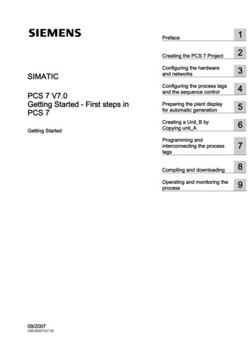
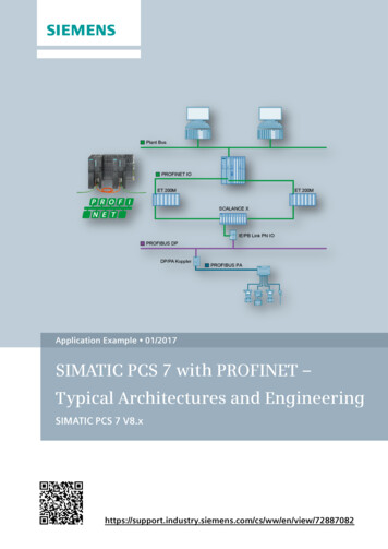
1 Task and Solution1Task and Solution1.1TaskIts flexible architecture and seamless integration into Totally Integrated Automation(TIA) from Siemens allows SIMATIC PCS 7 to be used in various applications andsectors. SIMATIC PCS 7 allows the implementation of requirements at all hierarchylevels of industrial automation, from the corporate management level through thecontrol level to the field level.Additional requirements to performance and the quantity framework in the fieldlevel push the integration of new technologies into PCS 7. The basis for such atechnology is provided by the open Industrial Ethernet standard of theProfibus&Profinet International (PI) Organization. Siemens AG 2017 All rights reserved1.2SolutionWith the integration of PROFINET (PROcess FIeld NET) as field bus, SIMATICPCS 7 supports a great number of technologies for the communication on the fieldlevel. The PROFINET, based in the international standards IEC 61158 andIEC 61784, combines the advantages of the open network standard Ethernet andthe field bus system PROFIBUS. PROFINET can be used as the only field bus orin combination with the proven PROFIBUS DP for the communication betweenautomation systems and process periphery.This description gives you a practical procedure for planning and configuringPROFINET in the PCS 7 environment. This application example provides a quickintroduction to the topic, gives you an overview of possible topologies and supportsyou with numerous step-by-step instructions (Getting Started character).OverviewThe figure below shows the most important components of the PROFINETsolution.Figure 1-1PCS 7 with PROFINETEntry-ID: 72887082, 1.3,01/20175
1 Task and SolutionThe automation task requires the following steps: Configuring distributed IO and field devices in HW Config Configuration of field devices in SIMATIC PDM Checking and setting the bus parametersThis description guides you through the subject PCS 7 with PROFINET and includesguidance on the following focal points: Basic knowledge such as architecture, PROFINET terminology etc. (Mediaredundancy and System redundancy) Selection of suitable components (released components) System limits or constraints Parameterizing and configuring the workbench in PCS 7Delimitation Siemens AG 2017 All rights reservedThis application example does not include a description of the following: Basic SIMATIC PCS 7 configuration Working and configuration with SIMATIC PDM Process-specific device configuration in SIMATIC PDMBasic knowledge of these topics is assumed.AdvantagesThe solution presented in this document offers the following advantages: Quick development of PROFINET know-how Description of typical scenarios, e.g. complete configuration, commissioningand device integration in PROFINET segments This reduces the planning and configuration overhead.PCS 7 with PROFINETEntry-ID: 72887082, 1.3,01/20176
1 Task and Solution1.3Hardware and software componentsThe application example was set up with the following components:Hardware componentsTable 1-1 – Automation components Siemens AG 2017 All rights reservedComponentNOTEOrder numberCPU 410-5H6ES7 410-5HX08-0AB0CP 443-16GK7 443-1EX30-0XE0 (V3.1)ET 200M (IM 153-4 PN HF)6ES7 153-4BA00-0XB0 (V4.0)AI8x0/4 20mA HART6ES7 331-7TF01-0AB0AO4x12Bit6ES7 332-5HD01-0AB0DI16xDC246ES7 321-1BH02-0AA0DO16xDC246ES7 322-1BH01-0AA0F-DO10xDC246ES7 326-2BF10-0AB0F-AI6x0/4 20mA HART6ES7 336-4GE00-0AB0SITRANS TH3007NG3212-0NN00SCALANCE X208-26GK5 208-0BA10-2AA3 (V4.5)IE/PB Link PN IO6GK1411-5AB00PA coupler6ES7 157-0AC83-0XA0SITRANS P DSIII7MF4432-1DA00-1AB6-ZPlease find the list of the PROFINET modules released for PCS 7 using“SIMATIC Process Control System PCS 7 Released Modules (V8.2)” viafollowing link: /109736547.The released modules of further versions can be obtained by changing theedition (dropdown menu) on the entry page.Table 1-2 – Engineering systemComponentNOTENoteSIMATIC PCS 7 ES/OS IPC547D W7Engineering station with PCS 7 V8.0 SP1/SP2SIMATIC PCS 7 ES/OS IPC547EEngineering station with PCS 7 V8.1SIMATIC PCS 7 ES/OS IPC547EEngineering station with PCS 7 V8.2When using different hardware, please observe the minimum requirements forinstalling the software components. The minimum requirements can be found inthe PCS 7 readme file.PCS 7 with PROFINETEntry-ID: 72887082, 1.3,01/20177
1 Task and SolutionStandard software componentsTable 1-3 –Software componentsComponentOrder numberNoteSIMATIC PCS 7 V8.0Part of Industrial PCSIMATIC PCS 7 V8.1Part of Industrial PC6ES7 658-3LD180YA5(Optional) For the configurationof field devices (100 tag)SIMATIC PDM PCS 7 V8.26ES7658-3LD280YA5Optional) For the configurationof field devices (100 tag)SIMATIC PDM PCS 7 V9.06ES7658-3LD580YA5Optional) For the configurationof field devices (100 tag) Siemens AG 2017 All rights reservedSIMATIC PDM PCS 7 V8.1PCS 7 with PROFINETEntry-ID: 72887082, 1.3,01/20178
2 Basics2Basics2.1Terminology PROFIBUS and PROFINETPROFINET differentiates between two different message applications: PROFINET CBA (Component Based Automation), not supported in PCS 7Communication across manufacturer borders (control level) of intelligentautomation components and system parts PROFINET IO, supported since PCS 7 V8.0 Upd.1Cyclic communication (IO data) from the controller with distributed field devicesWhile the function models of PROFIBUS DP and PROFINET are similar, a differentterminology is used for the individual technologies. These expressions arecompared in the table below.Table 2-1PROFIBUS Siemens AG 2017 All rights reservedCommunicationNOTE2.2PROFINETMaster slave procedure(Token-Passing)Real-time n SystemMaster class 1IO controllerField deviceSlaveIO devicePG/PCMaster class 2IO supervisorDevice descriptionGSD (ASCII)GSDML (XML)Address assignmentPROFIBUS DP addressIO device nameMessage size244 Bytes1440 BytesSubscribersmax. 125max. 250Transmission speedmax.12 MBit/s10/100 Mbit/s full duplexCycle timemin. 300 µsmin. 31.25 µsFor more detailed information on the comparison of PROFIBUS, PROFINET andEthernet, please see Chapter 6 “Further notes, tips and tricks, etc.”.Media redundancyThe availability of the IO devices in an IO controller is increased by ring topologywith media redundancy. If the transmission path in a ring is interrupted in oneplace, for example due to a disconnection of the ring line or because a node fails,then the redundancy manager immediately activates the alternative communicationpath.PCS 7 with PROFINETEntry-ID: 72887082, 1.3,01/20179
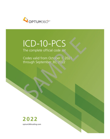
2 Basics2.2.1Redundancy procedure HRP and MRPFor building up a media redundancy with SIMATIC NET components for ringtopologies, the following procedures are available:Table 2-2HRP(Highspeed RedundancyProtocol)Max. reconfiguration time300 ms200 msAutomatic ring configurationNoYesMaximum number of nodesin the ring50Web Based ManagementYes for configurationYes (optional to STEP 7configuration)CLI (Command LineInterface)YesYesSNMP (Simple NetworkManagement Protocol)Yes for diagnosisYes (Additional to systemdiagnosis)STEP 7 configurationNoYesSourceSIMENS AGProfibus&Profinet International (PI)OrganizationNOTEFor setting up a ring redundancy with HRP or MRP, the network componentsmust support the respective procedure. A combination of PROFINET and HRPring in the process level is not released.Due to the STEP 7 configuration and system diagnosis possibilities, the proceduresfor the respective levels are recommended. System level: HRP - Configuration via the web interface of the switches Process level: MRP - Configuration in STEP 7 and system diagnosisFigure 2-1HRPSystem levelProcess levelMRP Siemens AG 2017 All rights reservedMRP(Media Redundancy Protocol)PCS 7 with PROFINETEntry-ID: 72887082, 1.3,01/201710
2 BasicsNOTE2.2.2Setting up a ring redundancy in the system level is possible, but not released in aPCS 7 environment.PROFINET process level with redundancy procedure MRPFor creating an MRP ring, the ring nodes (switch, IO devices) must support theMRP (Media Redundancy Protocol).The following limits must be observed: max. 50 nodes in the ring max.200 ms reconfiguration time (for 50 nodes in the ring) Siemens AG 2017 All rights reservedFigure 2-2MRP supportTelegram directionThe following Industrial Ethernet switches support the MRP function: SCALANCE X-200 as of Firmware-Version V4.0 SCALANCE X-200 IRT as of Firmware-Version V4.0 SCALANCE X-300 as of Firmware-Version V3.0 SCALANCE X-400 as of Firmware-Version V3.0 Increased flexibility Increased flexibility of the system (in case of a failure, the transmissiondirection of the telegram is changed) Additional diagnostic possibilities (topology editor)AdvantagesPCS 7 with PROFINETEntry-ID: 72887082, 1.3,01/201711
2 Basics2.3System redundancyThe system redundancy (System Redundancy Protocol) is a mechanism formaintaining the PROFINET connection between the IO controller and the IOdevices. It is characterized by a form of the PROFINET IO communication, in whichevery IO device builds up a communication link via the topologic network with oneof the two IO controllers (active and backup CPU) of an AS Redundancy Station. Incontrast to a unilateral connection of the IO device to only one IO controller, afailure of the CPU will not automatically lead to a failure of the linked IO deviceconnections.NOTEFor the system redundancy, the following components can be used: CPU 410-5HS7-400 H-CPU with FW V6.0ET 200M with FW V4.0 Siemens AG 2017 All rights reservedFigure 2-3 PROFINET with system redundancyPrimary connectionBackup connectionAdvantagesNOTICE High-performance access Failure of one CUP is compensated by switching to others Not affected by broken wires (process level) or in case of an IO device failureFor configurations with redundant automation system processes allconnected IO devices must support the system redundancy regardless ofthe connection path. If one IO device does not support the systemredundancy, stopping an AS sub-system will lead to a failure of the IOdevices.PCS 7 with PROFINETEntry-ID: 72887082, 1.3,01/201712
2 Basics2.4Typical PCS 7 architectures2.4.1System levelPROFINET is basically designed for common use in system and process level. Inorder to meet the security aspects and the real-time requirements in processautomation, both system and process level needs to be built up and integratedseparately from each other. The known architectures involving Ethernet can beimplemented in the system level.NOTEAn overview of SIMATIC PCS 7 architectures is described in the document“PCS 7 Standard Architectures” via the following view/32201963.The following graphic shows a sample configuration for a redundant automationsystem.Figure 2-4 Siemens AG 2017 All rights reservedRedundant automation systemSystem levelProcess level2.4.2Process levelIn PCS 7 many different configurations can be implemented with PROFINET as thefield bus (process level). The right configuration is to be selected depending on thesize of plant and the number of nodes. The general topologies are presented belowas well as their corresponding advantages and disadvantages relating to PCS 7For the connection of the field level to the automation system (AS), the internalPROFINET interface (from CPU with FW V6.0) is to be preferred. As an alternative,the CP443-1EX30* can be used in combination with the standard CPU (414-3,416-2, 416-3 and 417-4) with version V5.3.1 and higher.NOTEAs of PCS 7 V8.1 with CPU 410-5H FW V8.1 two PROFINET fieldbus segmentscan be realized by using the two PN/Ethernet interfaces of the CPU.PCS 7 with PROFINETEntry-ID: 72887082, 1.3,01/201713
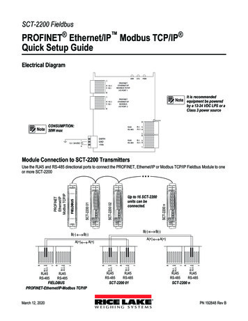
2 BasicsPROFINET configuration of a single automation systemA MRP ring or a tree structure can be used for a single configuration (comparablewith the monomaster system for PROFIBUS topology) according to requiredreaction time and number of IO devices. The MRP ring is the most cost-effectivesolution since no additional components are needed. The IO device internal 2 portswitches are used for the ring structure. In doing so, the IO device takes over thefunction of ring master. Siemens AG 2017 All rights reservedWith a single automation system all the basic structures are supported whichinclude: Line: simplest structure, but more prone to failure, since a device failurecauses an interruption in the line Star: implement an effective wiring with additional network components. Thenumber of nodes is depending on the switch. Ring: robust configuration with up to 50 IO devices and a maximumreconfiguration time of 200ms (for 50 ring nodes in use) Mixed configuration: any theoretical structure and flexible extension possible,partly prone to failure and complex–A mixed configuration (ring/start) with an MRP ring provides the bestpossible reliability. The MRP ring is composed of an IP controller and theswitches. The IO devices are to be connected to the switches.–The tree structure (a mixed configuration of line and star) with multichannel switches ( 8 ports) enables short reaction times. Up to 250 IOdevices and up to 62 switches connected in series, characterize thistopology.–Depending on the requirements, the adequate ring, tree or ring/starconfiguration must be chosen.Figure 2-5 – Single PROFINET configurationLineStarRingMixed configurationMRPMRPLineStarPCS 7 with PROFINETEntry-ID: 72887082, 1.3,Ring MRP MRP ring01/2017MRP support14
2 BasicsPROFINET configuration of a fault-tolerant automation systemFor the topology of a redundant configuration (can be compared with the redundantmaster system in the PROFIBUS topology), the requirement concerning theavailability of the IO devices is decisive. If simple availability is sufficient (noredundant connection paths), the topologies of the single PROFINET configurationcan be used. If the connection paths need to be redundant, we recommend a linetopology with an IO controller each at the beginning and the end. In case of anerror, the IO controllers of the H system can access all the remaining IO devices bymeans of the system redundancy via the Sync connection. The maximum numberof IO devices of this line must not exceed 64 devices.An RMP ring is possible, but does not have any advantage as compared to a linetopology of the same structure.NOTICEFor configurations with redundant automation system processes allconnected IO devices must support the system redundancy regardless ofthe connection path. If one IO device does not support the systemredundancy, stopping an AS sub-system will lead to a failure of the IOdevices. Siemens AG 2017 All rights reservedFigure 2-6 – Fault-tolerant automation system with PROFINETLinehighavailabilityPCS 7 with PROFINETEntry-ID: 72887082, 1.3,Starstandardavailability01/2017Mixed configurationLineStar15
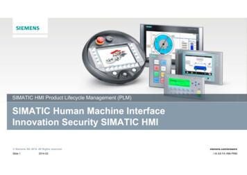
2 BasicsNetworking of different automation systemsWith PROFINET the time and costs for the assembly of system parts for severalAS (switchgear, for example) can be considerably reduced. By interconnecting allthe IO controllers (can be compared with the multimaster system in the PROFIBUStopology, not released for PCS 7) with a higher-level ring, every IO controller cancommunicate with the IO devices assigned to it.To avoid intersections and thus overloads or runtime delays during the PROFINETcommunication, the higher-level ring must be separated by a spur line. This spurline represents a "single point of failure" and should therefore be designed as shortas possible.This comprehensive connection can be used for singular and for highly availableautomation systems.Due to the real time band width, it is not recommended to operate all the IOcontrollers and all the IO devices in the same ring.The following figure shows a feasible configuration:Figure 2-7 – Networked automation systems with PROFINET2. AS3. ASDevice integrationMRP Siemens AG 2017 All rights reserved1. ASLineNOTEStarRing MRP MRP ringMRP supportThrough the utilization of PCS 7 V8.1 / PCS V8.2 and CPU 410-5H FW V8.1 aPROFINET configuration with two PROFINET segments can be realized. E. g.the first segment can be used for switchgear (drives and circuit-breakers) andthe second segment for all process devices.1. AS (highly available automation system)–all devices of this AS must support the system redundancy–no COs admissible as IO controller–connection to the ring without redundancy2. AS (single automation system)–MRP ring for reducing costs–expandable with external CPs as IO controllers (CPU 412. 417)up to 128 IO devices per CPPCS 7 with PROFINETEntry-ID: 72887082, 1.3,01/201716
2 Basics3. AS (fail-safe automation system)–direct connection of IO devices–short connection paths to the separated IO devices,for example with their own (yellow) network for fail-safe modules Siemens AG 2017 All rights reservedDevice integration–connection of drives, circuit-breakers, bus systems (PROFIBUS DP/PA)via switches to a high-level ring–unlimited data exchange with every AS–data traffic in the ring is limited to the connected devices–simple wiring–great data volume is possible–reduced planning time and costs2.5PROFINET communication2.5.1Real-time capabilityThe real-time capability (Real Time/Isochronous Real Time) of PROFINET isimplemented by a deterministic procedure. A transmission time (cycle time) for thetransmission of the data is (cyclically) calculated on the basis of the configureddata. This calculated time corresponds to the data exchange of the cyclic data (IOdata such as process values) in a defined period of time. The acyclic data (TCP/IPUPD/IP data such as engineering and diagnosis data) are distributed to thefollowing cycles depending on the available band width.Figure 2-8 Data structure of an Ethernet telegramIO data123 TCP/IP - UDP/IP datanFor the real-time communication the respective data are classified (real timeclasses), i.e. the higher prioritized data (cyclic data) are transmitted with priority ina reserved transmission band width.PCS 7 with PROFINETEntry-ID: 72887082, 1.3,01/201717
2 BasicsIn real-time communication, we differentiate between the following two performance levels:NOTE2.5.2 Real-Time (RT):transmission of prioritized data in a defined period of time (e.g. max 200ms) Isochronous Real-Time (IRT), not released for PCS 7:guaranteed transmission of the data in synchronized periods of time (e.g. witha transmission rate of 1000 µs, the IRT data are transmitted during the first 100µs). IRT is used for motion control applications, but not for PCS 7.Please find more detailed information on the overview, structure, functions andIO engineering of PROFINET in the system manual “PROFINET SystemDescription” via the following view/19292127.Field bus integrationFor the integration of further technologies, so-called proxies are used. At thePROFINET side, the proxy behaves like a PN device and at the PROFIBUS sidelike a PROFIBUS DP master (subsegment). Siemens AG 2017 All rights reservedFigure 2-9Proxy (IE/PB link PN IO)PROFIBUS DPNOTEPROFIBUS PAThe S7 routing functionality allows for a communication of a programming devicevia the IE/PB link PN IO to the lower-level PROFIBUS DP segment. Onlycompact devices are used as PROFINET DP nodes. These include flow meterswith a PROFIBUS DP connection, PROFIBUS PA devices connected via DP/DAcouplers etc.So device configurations can be carried outthe process values can be visualized by means of the OPC communicationPCS 7 with PROFINETEntry-ID: 72887082, 1.3,01/201718
2 Basics2.6Virtual Local Area Network (VLAN)VLAN-capable switches provide an alternative and flexible way for connectingPROFINET/Ethernet devices over a network. VLAN (Virtual Local Area Network)refers to a method in which several logical or virtual networks are created within aphysical network. There are two types of VLAN: Untagged (port-based) VLAN: The ports are assigned to VLANs, i.e. a switchcan support two independent (logical) networks. Tagged VLAN: The Ethernet frame is also equipped with tags containing aVLAN ID, which connects them through a VLAN network address.The figure below shows the structure of a simple architecture with VLAN.Figure 2-10 Accessibility of the ES to the Process busOS Siemens AG 2017 All rights reservedESSCALANCE XControl levelProcess levelAS01SCALANCE XSCALANCE XNOTEET200MPROFINET 2PROFINET 1ET200MSCALANCE XAS03ET200MPROFINET 3SCALANCE XAS02VLAN 1 – PROFINET 1VLAN 2 – PROFINET 2VLAN 3 – PROFINET 3You can obtain further information on VLAN and on the configuring of VLANsegments with SCALANCE switches in the entry "How do you configure a VirtualLocal Area Network (VLAN) in PCS 7?", via the following view/66807297.PCS 7 with PROFINETEntry-ID: 72887082, 1.3,01/201719
3 Installation and AssemblyInstallation and Assembly3For this installation example, a configuration consisting of an ES/OS single placesystem with a monomaster system (CPU 410-5H) and a low
Siemens provides products and solutions with industrial security functions that support the secure operation of plants, systems, machines and networks. In order to protect plants, systems, machines and networks against cyber threats, it is necessary to implement - and continuously maintain - a holistic,