Transcription
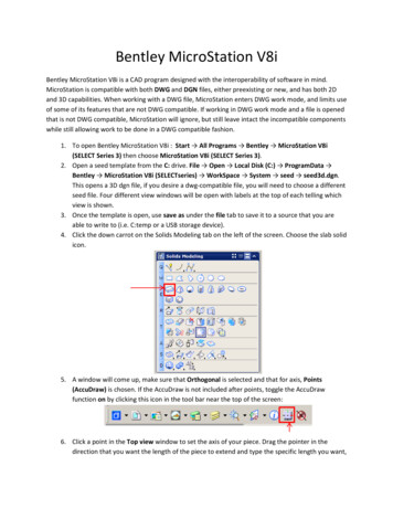
Bentley MicroStation V8iBentley MicroStation V8i is a CAD program designed with the interoperability of software in mind.MicroStation is compatible with both DWG and DGN files, either preexisting or new, and has both 2Dand 3D capabilities. When working with a DWG file, MicroStation enters DWG work mode, and limits useof some of its features that are not DWG compatible. If working in DWG work mode and a file is openedthat is not DWG compatible, MicroStation will ignore, but still leave intact the incompatible componentswhile still allowing work to be done in a DWG compatible fashion.1. To open Bentley MicroStation V8i : Start All Programs Bentley MicroStation V8i(SELECT Series 3) then choose MicroStation V8i (SELECT Series 3).2. Open a seed template from the C: drive. File Open Local Disk (C:) ProgramData Bentley MicroStation V8i (SELECTseries) WorkSpace System seed seed3d.dgn.This opens a 3D dgn file, if you desire a dwg-compatible file, you will need to choose a differentseed file. Four different view windows will be open with labels at the top of each telling whichview is shown.3. Once the template is open, use save as under the file tab to save it to a source that you areable to write to (i.e. C:temp or a USB storage device).4. Click the down carrot on the Solids Modeling tab on the left of the screen. Choose the slab solidicon.5. A window will come up, make sure that Orthogonal is selected and that for axis, Points(AccuDraw) is chosen. If the AccuDraw is not included after points, toggle the AccuDrawfunction on by clicking this icon in the tool bar near the top of the screen:6. Click a point in the Top view window to set the axis of your piece. Drag the pointer in thedirection that you want the length of the piece to extend and type the specific length you want,
then click the mouse. This will set the length of the piece. Do the same for the width (dragging,entering the width, and click). For the height, simply type the desired height and click. For theexample shown, the dimensions are 2x3x1. Click the X on the Slab Solid window to close thetool.7. Now your slab is set, you can zoom in or out in any of the views by rolling the scroll wheel onthe mouse in the view window you wish to zoom, or move around your workspace by clickingthe scroll wheel, holding down and dragging the screen.8. To round the edges on the end of the piece, use the fillet edges tool under the Solids Modelingtab:In the window that comes up, set the radius that you want for your fillet, then, in the isometricview, select the corner edge that you want rounded, it will turn yellow, click again to carry outthe command. Do this same procedure to the next edge. In the example, a radius of 0.5 is usedfor both corners. Close the Fillet Edges window to exit the tool.9. To put a hole through the slab, use the hole feature, it is found under the Feature Modelingtab:
10. In the Hole Feature window that comes up, choose the diameter and other specifications forthe hole. Then click on the slab to select it as your object. It is easiest to work in the top viewfor this feature. A tentative sketch will guide you while placing your hole. To place the hole, thepointer will snap to the center of the end of the slab, click the mouse and let go then drag themouse along the direction you want the hole to be and type in the distance you want the holeto be from the point where you clicked and then click again. The whole is now placed throughthe slab. The example hole has a radius of 0.5 and is centered lengthwise and widthwise on thepiece. Close the Hole Feature window.11. To change the display style and add shading, click and hold the view display mode icon in theisomeric view window until a drop down menu appears, choose Illustration with Shadows.
12. Before adding dimensions, you’ll need to create some settings. Click on Element DimensionStyles, in the window that comes up, click the Create Style icon:and name your stylewhat you wish. Then, in the tabs to the right, set the amount of decimal places and units (underUnits), the size of the font (under Text), and other adjustments you want. Then, make sureyour style is selected and click the Set Style Active icon:and close the window. To adddimensions, click Tools Dimensions Dimension Element. Hold the mouse over the sectionthat you want to add a dimension for, it will turn purple. Click on the section and drag thedimension away from the piece and place it where you wish. Repeat for the remaining sections.
13. To print the part, go to File Print. In the new window, there will be options and a preview ofwhat will be printed. By default view that you had active will be the one previewed, to changethis, choose the view you want to print from the View drop down. With the print window open,you can roll the mouse over the active view and use the scroll wheel to zoom in or out to yourliking, then to update the preview click the Update from View buttonsettings are correct, click the printer iconto print the piece. Once all of the
Bentley MicroStation V8i is a CAD program designed with the interoperability of software in mind. MicroStation is compatible with both . DWG. and . DGN. files, either preexisting or new, and has both 2D and 3D capabilities . When working with a DWG file, MicroStation enters DWG work mode, and limits use