Transcription
Creating PDF Filesfrom MicroStationV8i DGN Files
IntroductionT.D.O.T. Design Division personnel have two methods available to them for producing PDFfiles from plan sheets in MicroStation. Both of these are described in this document. Therecommended method is with InterPlot Organizer, which is used for batch plotting andgenerating PDF plan sets. They can also use MicroStation Print to produce individual sheetPDF files.Consultants that use MicroStation’s Print Organizer tool for batch plotting can use thatsection for guidance in producing PDF plan sets.A single PDF file should be created that contains all required sheets for all plan sets exceptfor the final construction plans turn in. For final construction plans, each individual sheet isgenerated as a separate PDF file. They can then be combined in a PDF portfolio where theproject engineer can digitally sign them each.PDF Sheet SizesAll Plan sheets in PDF files used for posting to FileNet must be set up at full size. OtherPDF plans sheet submittals may be half size as stipulated in the T.D.O.T. Design DivisionGuidelines.This document contains a section at the end describing the correct way to print from PDFfiles to avoid scaling errors. It shows document and paper sizes as well as how to print fromeither full or half size to generate any required prints you may need.1
(If you are unsure how to proceed with the following steps, please contact CADD Support,your office IT staff or submit a Remedy helpdesk ticket.)Connecting to Printers/Plotters on new print servers:Users must remove old plotters (which will be ghosted) and add to the newly named plotters- To connect to the plotters in your region/office, you will need to go to the Start menu. Oncethere type the appropriate dialog to access your plotters for your region/office:oHeadquarters: \\HQPRINToRegion 1: \\R1PRINToRegion 2: \\R2PRINToRegion 3: \\R3PRINToRegion 4: \\R4PRINTOnce you have found the plotter you want to connect to, right-click and select Connect. toconnect to the plotter. Do this for each plotter you need connected.PURPOSEThis document provides instructions for a new plotting workflow for full size design fileswhen using Projectwise Interplot Organizer and IPLOT within MicroStation to matchcurrent needs and standards.CURRENT VERSIONS OF APPLICATIONS THAT USE SETTINGS FILES IPLOT in MicroStation V8i Select Series 2 (08.11.07.443) Projectwise Interplot Organizer V8i Select Series 2 (08.11.07.420) Projectwise Interplot Organizer CONNECT Edition (10.00.00.52)HISTORYThe plotter migration to the new 2008 Windows servers changed the print server names andplotter names found hardcoded within each *.set file. In most cases, there are many settingsfiles for each plotter queue. Interplot settings files (*.set) are located on users’ computers inthe following directory:C:\Users\Public\InterPlot Standards\Settings2
The hope is to streamline the process of creating/updating these files and plotter queues, aswell as, providing users with better performance and adherence to current plottingstandards.BENEFITS OF NEW PLOTTING WORKFLOWBy creating PDF settings files, this provides the following solutions: Removes dependencies found in current settings files by being hardcoded tospecific plotters Users have more flexibility to print and plot by allowing them to select their device When instructions are followed, they provide a more consistent printed productwith the correct scales Less to manage and maintain – all regions/offices get the same settings filesoThis should also reduce the number of plotter queues on the print servers Creation of digital copy of every full size sheet to be stored on network When instructions are followed, full size PDF can be scaled down to half size forprinting to printers – faster and less expensive than printing to plotters; potential toreduce the number of plotters by replacing with additional printers for additional costsavingsPDF Plan Sets from InterPlot Organizer1. Open InterPlot Organizer and create a plot set.The next several pages illustrate the set-up of sheets in InterPlot Organizer. Theyvary by type and when your plans were originally set up. Once you have your sheetsset up in InterPlot Organizer you scan skip to page 7 and step 2.NOTE: For users who cannot create PDFs with InterPlot Organizer due to issuewith DGNs files embedded with Excel spreadsheet which was updated toOffice 365 and this has caused PDFs creation in InterPlot Organizer for some.To resolve such issue, we recommend users to use Print Organizer asinstructed on page 16 of this document.3
Document Sheet SizesRegular Full Size:33” X 21”Cross Section Full Size:33” X 21”Regular Plan Sheets (Full Size)Note:Ensure documents are sent to correct printer directory.Head Quarter - \\hqprint\HQ FullSize PDFRegion 1- \\r1print\R1 FullSize PDFRegion 2- \\r2print\R2 FullSize PDFRegion 3- \\r3print\R3 FullSize PDFRegion 4- \\r4print\R4 FullSize PDF4
Cross Section Sheets (Full Size)Note:The main difference between the regular ORG* settings files normally used with InterplotOrganizer and the PDF* settings files are no paper size is set and they use an internalrotation setting of zero.Full Size PDF Selection in Interplot OrganizerBoth Regular Plan and Cross Section Sheets must use PdfEnglishFul.5
For 8 ½ X 11 Permit Sketches:Create a plot set using the following settings files:Settings FileB&W or ColorOrientationPdfEnglishPermitLand.setBlack and WhiteLandscapePdfEnglishPermitPort.setBlack and hese settings files utilize a PDF plot shape in the permit sketch borders that is drawn withcolor 253.For permits set up prior to October 2007 when the PDF plot shape was added to thepermit sketch border cells, use the Draw Plot Border tool to set symbology and manuallyadd the PDF plot shape by drawing over the outside border of the permit. This tool can befound under the TDOT drop down menu at TDOT Tools Draw Plot Border or fromGeopak’s D&C Manager at Drafting Standards Tools Plot Border.6
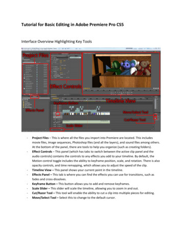
1. Go to File Export PDF. When one or more plots are selected in the list, you can rightclick on your mouse and choose Export PDF from the pop-upmenu. There is also an icon to launch this function on the menu bar The Export PDF dialog display varies slightly from previous versions andincludes an option to create separate PDF files for each sheet. This optioncould be used when creating PDF documents for final construction plans.7
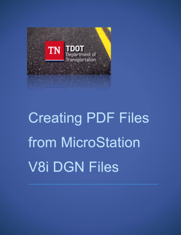
2. In the Export PDF dialog, click on PDF Format Configuration. Make the followingsettings: Resolution: 600 dpi Rotation: 270 VersionCompatibility:Acrobat 8.0 and later Searchable Text:clicked On. RGB JPEGCompression:clicked On.After the settings are made, select OK in the PDF Format Configuration dialog.3. Back in the Export PDF dialog, you may wish to click on the option to InvokePDF viewer when done to automatically open the new PDF file for review. Click Create PDF.4. In the Save PDF File dialog, navigate to your project folder, enter a filename and clickSave.8
If you had the Generate a separate PDF file for each plot clicked Onthen you are prompted for the folder to place the sheet PDF files in.9
If the option to Invoke PDF viewer when done was clicked, the new PDF file isopened when generation is completed.5. Back in the Interplot Organizer dialog, go to File Save and save the plot set forlater recall as needed.10
Creating PDF Portfolios for Final Construction PlansIn the previous example, we created a plan set of all of the sheets. For final constructionplans, each sheet must be a separate PDF. The previous steps can be used to createindividual sheet PDF files as well. These individual PDF files are later combined in aportfolio so that each can be digitally signed by the engineer. For full documentation oncreating PDF portfolios and digitally signing plans refer to documentation file DigitalSignature Certification Workflow.pdf .Adobe Acrobat 11 Standard & Pro In the Print dialog under Page Sizing & Handling set:Select Size and Fit.Choose Paper Source by PDF page size clicked OFF.Turn Landscape ON under Orientation.11
In Properties tab under Basic Settings:Select 11x17 for Page Size.12
Creating PDF files using MicroStation Print1. In the MicroStation plan sheet DGN file, change the default view attributes to LineWeights on, Data Fields off and Fill on. Adjust other view attributes if needed as shownbelow2. Turn on level DESIGN - SHEET - Plot Shape if it is not on. Snap to the corners of thepurple PDF plot shape on that level to place a fence around the plan sheet. It follows theinside sheet border on the right and is visible to the left of the inside sheet border on theleft. On cross section sheets, it drops below the offsets at the bottom of the sheet grid.Warning:Do not use the plot snap points on the sheet border to set up the fence. These are set up forplotting to plotters that have the margins set at 0, not for PDF production.13
3. MicroStation Print uses the current view attributes to set up the plot parameters. Turn offlevels DESIGN - SHEET - Plot Shape and DESIGN - SCRATCH - User 1.4. Open MicroStation Print. Go to File Print or click the printer icon on the Standard toolstrip.or from the TDOT Design Division tool strip, Plotting tool box5. Attach the desired Bentley driver. In the MicroStation Print dialog go to File SelectBentley Driver or click the browse icon next to the Bentley driver option on the dialog.Use plot configuration files Tdotpdfful.pltcfg, Tdotpdffulc.pltcfg (full size color) orTdotpdfhaf.pltcfg to create PDF files. Using the fullsize plot driver, the Paper Size will default to PDF Regular Full (33 X 21) forregular plan sheets. Other paper options include PDF XS Full and PDF Permit Full. The Print Scale should come out at the correct scale by default based on the Paper Size. Ifthe scale is incorrect, the fence may need to be adjusted.14
6. In the MicroStation Print dialog, click the Print to File icon. The Save Print As dialogopens. Adjust the folder and filename as needed and click OK to save the PDF file.15
PDF Plan Sets from MicroStation Print OrganizerUsers that use MicroStation Print Organizer can utilize the same MicroStation Print plotconfiguration files to set up complete plan sets in a single PDF file. This is preferable toindividual files for each sheet, which is only needed for final construction plans.We have two printing methods for Print Organizer.Method 1. Our Recommendation - For users that want to skip having to define printstyles as shown in method 2. We recommend users to downloadTDOTPlanSheet.dgnlib from CADD download page and open Print Organizer from thisfile because print styles have already been predefined. When the file is downloaded andextracted, it resides in this directory C:\Users\Public\Print Organizer. It is advisable tocopy file from this directory and paste it in a project folder.1. Copy TDOTPlanSheet.dgnlib from C:\Users\Public\Print Organizer.16
2. Paste TDOTPlanSheet.dgnlib into a project folder.3. Open TDOTPlanSheet.dgnlib file then go to File Print Organizer17
4. Print Organizer window5. To create PDF, go to File Add Files to Set. The files can be added from any projectfolders if Print Organizer is opened from TDOTPlanSheet.dgnlib.6. Add input files and apply print styles then click OK.18
7. Review the resulting Print Area and Scale values for each plot to make sure allsheets have been captured correctly. A Print Area defined by View rather than Fencewith an odd Scale indicates problems finding the PDF plot shape.8. Input files without Print Styles applied, the scale would be off.9. To apply Print Styles, highlight all the sheets and go to Tools Apply Print Stylethen choose PDF Regular Full.19
10. The scale should be corrected after applying Print Styles.11. Click the Printicon to open the dialog to generate the PDF file for the plan set.Name the file folder destination and click OK to general the PDF plan set.20
Method 2. Before opening Print Organizer, we suggest a blank DGN file be created thenopen Print Organizer from within the window. This procedure shall be followed if usersdesire to save print styles for future print jobs.1. In MicroStation create new file window, click on New file2. Enter File name and click Save21
3. Select File name and click Open4. Open Printer Organizer in MicroStation5. In Printer Organizer, select Tools Define Print Styles22
6. Choose New in Print Styles7. Rename New Print Style to PDF Regular Full8. Under Printer tab, select Tdotpdfful for Printer driver configuration file.23
9. Fill in as shown for the rest of tabs.DisplayFence24
Type InAdvanced25
MainAfter all the settings for the print style have been made to control the output of the PDFfile, you must savethe settings and close print style window.10. . Then back in Print Organizer, go to File Add Files to Set to add the individualDGN files for the sheets to the plot set.26
11. All added sheets appear as Input files in Create Print Definitions and ensure PDFRegular Full is selected for Print Style name.12. Review the resulting Print Area and Scale values for each plot to make sure allsheets have been captured correctly. A Print Area defined by View rather thanFence with an odd Scale indicates problems finding the PDF plot shape.27
13. Click the Printicon to open the dialog to generate the PDF file for the plan set.Name the file folder destination and click OK to general the PDF plan set.14. Before closing out of Print Organizer, go to File Save As and this will be your printsetting which will retain your Print Styles that you defined. This is a way to avoidhaving to define print styles every time you use Print Organizer and you must Savebefore existing each time.28
15. For next print job using the same print setting, open the same DGN file when printstyles were created and go to File Print Organizer then in Print Organizer go toFile Open16. Select Print Organizer Setting that was saved from previous print job.29
17. When Print Organizer Setting opens, you will see the list of files from your previousprinting job.18. To make new PDF plan set, Delete existing files19. All files are clear but Print Organizer Setting remains.30
To add new files, refer to step 10 above.Also, to determine if your print styles have been saved or not highlight your saved PrintOrganizer setting and go to Tools Define Print Styles. Print Styles window shouldopen with setting shown in step 9.If Print Styles window opens with blank information, that means no Print Styles aresaved.31
Our recommendation is to have users open saved Print Organizer setting from originalDGN file when Print Styles were set.Printing PDF plan sheet files1. Open the PDF file with Acrobat.2. Go to File Print or click the Print icon3. Make the following settings in the Print dialog to ensure that the sheets arescaled correctly. Under Printer pick the printer or plot queue that has the desired sheet size forthe plot. In the Print dialog click on Properties:Under Paper Source or Page Setup (depends on printer), set Paper Sizebased on the desired paper size when printed. Use the following as aguide:17 x 11:Tabloid or 11X1732
After the settings are made, select OK in the PDF Format Configuration dialog. 3. Back in the Export PDF dialog, you may wish to click on the option to Invoke PDF viewer when done to automatically open the new PDF file for review. Click Create PDF. 4. In the Save PDF File dialog, navigate