Transcription
MicroStation V8 CADStandards Training Guide Improve Productivity Integrate Workflows Manage Highway Information
Table of ContentsTable of ContentsTABLE OF CONTENTS .IIINTRODUCTION . IVWHY NEW STANDARDS?. IVABOUT THIS COURSE . IVCOURSE OBJECTIVES . IVBEFORE YOU BEGIN . IVCONVENTIONS IN THIS COURSEWARE . IVTYPOGRAPHIC CONVENTIONS . VCHAPTER 1: OVERVIEW OF V8 FUNCTIONALITY. 1-1LESSON OBJECTIVES . 1-1INTRODUCTION TO MICROSTATION V8 . 1-1DGN FILE FORMAT . 1-1AUTOCAD COMPATIBILITY . 1-2MODELS . 1-2CELLS . 1-2LEVELS . 1-3DGN LIBRARIES . 1-3TEXT AND DIMENSION STYLES. 1-3DESIGN HISTORY. 1-3RASTER MANAGER . 1-4WORKMODES . 1-4NEW INTERFACE AND TOOL ENHANCEMENTS . 1-4HANDS ON EXERCISE: EXPLORING THE V8 INTERFACE . 1-4CHAPTER 2: SHA CAD STANDARDS CONCEPTS. 2-1LESSON OBJECTIVES . 2-1SHA STANDARD WORKSPACE . 2-1WORKSPACE VERSIONING . 2-4HANDS ON EXERCISE: USING THE V7 WORKSPACE . 2-5HANDS ON EXERCISE: OPENING A V7 FILE USING THE V8 WORKSPACE. 2-6FILE NAMING CONVENTION . 2-7FILE NAMING WIZARD . 2-10HANDS ON EXERCISE: FILE NAMING WIZARD . 2-13PROJECTS MANAGED THROUGH PROJECTWISE . 2-15USING MICROSTATION WITH PROJECTWISE AND THE CAD STANDARDS . 2-16PROJECTS STORED ON A CAD SERVER. 2-17FILE OWNERSHIP . 2-17SEED FILES . 2-17LEVEL NAMING . 2-18LEVEL DISPLAY. 2-18HANDS ON EXERCISE: LEVEL DISPLAY . 2-22DGN LIBRARY . 2-24LEVEL MANAGER . 2-24LEVEL FILTERS . 2-25HANDS ON EXERCISE: LEVEL FILTERS . 2-26CELLS . 2-29LINE STYLES . 2-29SCALING . 2-29FONTS AND TEXT SIZES . 2-29SHA V8 00036/5/2004ii
Table of ContentsTEXT STYLES . 2-30DIMENSION STYLES . 2-30DETAIL MODEL . 2-31HANDS ON EXERCISE – USING THE SHA DETAIL MODEL . 2-32COLOR TABLES . 2-353D AND 2D FILES . 2-36CHAPTER 3: BARMENU. 3-1LESSON OBJECTIVES . 3-1SHA CAD STANDARDS INTERFACE. 3-1RELOADING THE SHA BAR MENU . 3-3HANDS ON EXERCISE: USING SHA CAD STANDARD MENUS (PLATS AND SURVEYS). 3-4HANDS ON EXERCISE: USING SHA CAD STANDARD MENUS (GENERAL) . 3-6CHAPTER 4: REFERENCE FILES . 4-1LESSON OBJECTIVES . 4-1REFERENCE FILE CONCEPTS . 4-1ATTACHING A REFERENCE FILE COINCIDENTLY . 4-2SHA BORDER. 4-4ATTACHING A REFERENCE FILE USING SAVED VIEWS . 4-4LAYOUT FILES USING LIVE NESTED REFERENCES . 4-5HANDS-ON EXERCISE: COMPOSING PLAN SHEETS . 4-7CHAPTER 5: PLOTTING . 5-1LESSON OBJECTIVES . 5-1PLOTTING AT SHA . 5-1PLOT SIZES . 5-1COLORS . 5-1LINE WEIGHTS AND THICKNESSES . 5-2HANDS ON EXERCISE – USING IPLOT . 5-3HANDS ON EXERCISE - USING STANDARD MICROSTATION PLOTTING . 5-4CHAPTER 6: TOOLS. 6-1LESSON OBJECTIVES . 6-1MCPC (MORE COGO PLOTTING COMMANDS) . 6-1CHAPTER 7: INROADS . 7-1LESSON OBJECTIVES . 7-1LOADING INROADS THROUGH THE IDS TOOLBOX . 7-1NEW INROADS 8.4 FUNCTIONALITY . 7-1PROCESSING ICS FILES . 7-3HANDS ON EXERCISE – IMPORTING AN ICS FILE . 7-4SHA V8 00036/5/2004iii
IntroductionIntroductionWhy new Standards?The last comprehensive release of CAD Standards by Maryland State Highway Administration was in1995. At that time, the CAD Standards could be used for virtually any version of Bentley’s MicroStationsoftware. Also, the 1995 release of the CAD standards was not all inclusive.However, the release of MicroStation V8 in early 2002 brought with it a change in MicroStation’s fileformat as well as tighter integration with other products that have been adopted by Maryland StateHighway (ProjectWise, IPLOT). To fully take advantage of the new functionality within MicroStation V8, achange in the CAD Standards was crucial. The IDS Team took on the task of developing the new CADStandards and tools to better target the workflow used by Maryland State Highway.About This CourseThis course will provide you with the fundamental information you need to use Maryland State Highway’sV8 CAD Standards: First Edition within MicroStation V8.This courseware has been designed to emulate the progression of design projects with a very simpleworkflow in mind. This workflow serves as a reference more than a guideline. It teaches concepts andprocedures by walking you through common project tasks in MicroStation V8 using the CAD Standards. Itbreaks the tasks up into short, easy to understand segments. Training classes using this courseware cancombine hands-on learning, visual aids and lecture.Course ObjectivesWhen you complete this course, you will understand the following: New features in MicroStation V8 How the new V8 features relate to the MDSHA CAD Standards How to use Bar Menu to place MicroStation elements How to compose a display How to plot a displayBefore You BeginBefore beginning this course, we recommend that you have a working knowledge of MicroStation J.Although not necessary, familiarity with the 95 Standards is not required, it may be helpful. Weappreciate the comments from you and will incorporate those comments in the future releases of thiscourseware.This class is NOT intended for new MicroStation users.Conventions in This CoursewareThe following conventions are used throughout this courseware.LessonsEach chapter of this courseware is a lesson. A lesson describes a general area of MicroStation V8 as itrelates to Maryland State Highway Administration and the CAD Standards. Generally, the chapters focuson a few areas of a design process using related MicroStation and CAD Standard features. A lesson inSHA V8 00036/5/2004iv
Introductionthe courseware is made up of tasks – each task relates to a series of MicroStation commands. Thenumber of tasks varies from lesson to lesson.Hands On ExercisesEach lesson may contain several individual hands on exercises, which are written in a sequential formatto mimic the operational procedures. It contains numbered steps that list specific instructions, such aswords to type, specific keys to press, or commands to choose from the menus. The instructions arefollowed by comments describing what is happening in the program, reasons for the results you see, andpictures to help you identify certain elements of MicroStation, such as toolbar, buttons, dialog boxes orforms.Note: Notes point out special details that you should consider.Important:Important notes point out details which, if ignored, could seriously adversely affect youruse of MicroStation V8.A Cool Tool:Cool Tools point out powerful MicroStation features that make your work easier.Typographic ConventionsThis courseware uses the following typographic conventions: Tahoma Bold type indicates the names of most elements of the user interface, such aswindows, dialogs, fields, rows, features, and Wizards. Tahoma Bold Italic type indicates specific information you enter in to fields. SMALL CAPS indicate the names of keyboard keys, such as TAB or CTRL.SHA V8 00036/5/2004v
Chapter 1: Overview of V8 FunctionalityChapter 1: Overview of V8 FunctionalityLesson ObjectivesIn this lesson, you will learn about some of the new functionality included in MicroStation V8. The topicsare covered as follows: Introduction to MicroStation V8 DGN File Format AutoCAD Compatibility Models Cells Levels DGN Libraries Text and Dimension Styles Design History Raster Manager Workmodes New Interface and Tool EnhancementsIntroduction to MicroStation V8MicroStation V8 is considered a major upgrade compared to previous releases of the MicroStationsoftware. One of the most substantial improvements is the redesign of the MicroStation file format. Thischange in file format not only eliminates constraints placed on users in older versions, but also allowsbetter compatibility with AutoCAD.Although there are many changes in functionality and tools in MicroStation V8, we will briefly cover themost significant changes. Any changes that greatly affect the use of SHA’s CAD Standards will be coveredin more detail later in the guide.Important:This training guide covers MicroStation functionality up to and including V8.01.02.15.DGN File FormatPrevious versions of MicroStation had various limitations placed on a MicroStation file.Whereas in earlier versions the user had to always be concerned about the size of the MicroStationdesign plane, now the design cube is defined using double precision coordinates. This means the designplane within a MicroStation V8 file is greatly expanded in size (about two million times larger in eachdirection), which should resolve most “Element outside design plane” errors.The redesign of the DGN file format also decreases the actual file size of MicroStation files, MicroStationfiles generally take up less disk space than the same file in V7 format.The expanded design cube also allows larger MicroStation elements; vertices of an element are no longerlimited to 101, this has been expanded to 5000 in MicroStation V8. This also affects fence clipping whenattaching reference files. Many more clipping masks may be defined in V8.SHA V8 00036/5/20041-1
Chapter 1: Overview of V8 FunctionalityAll V7 DGN files must be converted to the V8 format before they can be edited in MicroStation V8. Thiscan be done individually, or in batch mode.Important:Once a file has been converted to V8, the file cannot be reopened in MicroStation Junless the file is converted to V7 format. New functionality in MicroStation V8 will not beconverted back to the V7 version of the file. This could result in “lost” elements.Although V7 files must be converted in order to be edited in V8, V7 files may be referenced into V8 fileswithout conversion. Additionally, 3D files may now be referenced into 2D design files.The new file format also allows the DGN file size to be larger. The design file size was limited to 32 Mb inMicroStation J. While the V7 file size limit did not affect most MicroStation drawings, files using CivilApplication software such as InRoads or GEOPAK were many times affected by this limitation (typicallywhen visualizing DTMs and Cross Sections). The maximum physical size of the DGN file is limited only bythe operating system (for example, the Windows NT file size limit is 4 GB).AutoCAD CompatibilityAutoCAD files may now be opened, edited, saved and referenced in the native AutoCAD format. Paperspace and model space are supported, as well as the ability to access AutoCad blocks and fonts withoutconversion.ModelsMicroStation V8 introduces the concept of models. A DGN file is now made up of one or more models(think of models as element “containers” within a MicroStation file). A DGN file can have an unlimitednumber of models, each with its own name, working units and 8 views.Note: Whereas each model in a DGN file may have its own unit system, levels are DGN file specific, notmodel specific.There are two types of models that can be created. Design models can be either 2D or 3D and consists of design geometry. Sheet models are used to attach references for composing drawings.CellsCell sizes are unlimited in the MicroStation V8 DGN file format and the length of a cell name has beenexpanded to approximately 500 characters.Cells are now stored as models in a DGN file. Therefore, a cell library may be opened in MicroStation andedited; just as any other MicroStation element is edited.After placing a cell in a drawing, the text in an unshared cell may be edited. This may replace the needfor Enter Data Fields within cells.2D and 3D cells may now reside in the same library and there is no longer a restriction on placing 3Dcells in a 2D file.Just like V7 DGN files, V7 cell libraries must be converted to V8 format before they may be used in aMicroStation V8 session.SHA V8 00036/5/20041-2
Chapter 1: Overview of V8 FunctionalityLevelsIn the MicroStation V8 DGN file format, the number of levels is unlimited, and the minimum number oflevels is 1 (named Default).Unused levels may be deleted out of a DGN file.All levels are named and have default colors, line weights, and line styles, providing the foundation fornumerous enhancements, one being the ability to place elements ByLevel.The concept of V7 Level Symbology has been expanded with the introduction of Level Overrides.Overrides now allow you to set level symbology PER LEVEL.Perhaps the most important benefit of the new level system is that it is much easier to standardize levelstructures across DGN files.DGN LibrariesDGN Libraries are DGN files that contain levels, text styles and dimension styles. They are designed to bea portable container for CAD Standards.DGN libraries may be used as a “seed file” or attached to an existing DGN file.A DGN file may have multiple DGN Libraries attached. These libraries can be attached manually or viaworkspace configuration variables.Text and Dimension StylesText and dimension settings may now be saved by [style] name and shared corporate-wide via DGN andDGNLIB files.Text and dimension elements that use styles are automatically updated if the style is edited.“Parent” and “Child” styles may be used to account for slight variations in a similar set of text ordimension settings.Design HistoryThe Design History feature of MicroStation V8 enables you to restore revisions of a DGN file. A revisioncan be a milestone in the development of a design. When you create a revision, Design History capturesthe state of the DGN file at that moment. To document the revision, Design History records your user IDand the current time and date, and allows you to enter a comment.SHA V8 00036/5/20041-3
Chapter 1: Overview of V8 FunctionalityDesign History is an optional feature of MicroStation V8. When enabled, Design History stores historicalinformation inside the DGN file. When you initialize a DGN file's Design History, the file grows to record asnapshot of the design. As you add revisions, the file continues to grow to hold the deltas.Raster ManagerRaster Manager is used to control the display of one or more raster images in a design file view.Raster Manager replaces both the Image Manager and Raster Reference dialog boxes from V7. ImageManager projects may be imported into Raster Manager.WorkmodesMicroStation V8 includes 3 different workmodes to ensure compatibility with V7 files and AutoCAD files. DGN Workmode enables all V8 functionality. DWG Workmode disables any V8 functionality that is not compatible with DWG and DXF files. V7 Workmode disables all V8 functionality that is not compatible with V7 files.New Interface and Tool EnhancementsMany new interface and tool enhancements are included in MicroStation V8.Below is a list of some of the major changes: File preview in the MicroStation Manager New Element Attribute dialog Message Center in the status bar Place arc in either direction Automatic visual element identification Scale and rotate elements About Center New hatching and patterning enhancements AccuSnapHands on Exercise: Exploring the V8 InterfaceIn this exercise, we will take a few moments to explore the V8 interface. Although there are manychanges in the interface and tools, we will only look at a few since our main focus is on the way SHA isimplementing V8 with the new CAD Standards.Launch MicroStation V81. Double-click the MicroStation (CADSTD) icon on the desktop.SHA V8 00036/5/20041-4
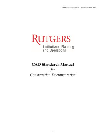
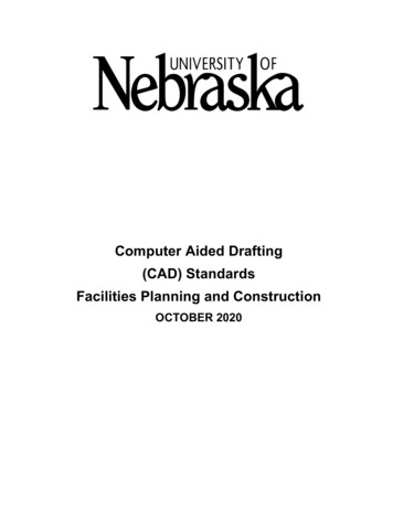
Chapter 1: Overview of V8 Functionality2. At the MicroStation Manager dialog, click on the selection under List Files of Type.Additional file types have been added, particularly CAD Files (DGN, DWG and DXF) andCell Files.A Cool Tool:Notice in the MicroStation Manager dialog the Show File Icons toggle. Checking thetoggle changes the file view so that each file name also has its corresponding icon. Nowat a glance, the user can differentiate V7 files from V8 files.3. Open the design file C:\Training\Chapter1\xBL-0000 training.dgnThis is the SHA border sheet file which we will discuss in more detail later in the course. At this point weare just accessing this file to get familiar with the V8 interface.Note: Although the MDSHA IDS Main Menu will load when the MicroStation file is opened, we are goingto ignore the menu at this point.“New” Tool BarsIn MicroStation V8, a few of the toolboxes have been renamed and may look a bit different than they didin V7.1. Notice the toolbox below the pull down menus. This is the Attributes toolbox.Level FiltersLevel NameColorStyleWeightPreview2. Notice the new Primary toolbox.Tools on the Primary toolbox are from left to right; Models, References, Raster Manager, LevelManager, Level Display, Element Information, Toggle AccuDraw, PopSet.A Cool Tool:V8 toolboxes respond to a right mouse click. This allows the user to quickly “customize”the contents of a particular toolbox.3. Right click on the Primary toolbox.SHA V8 00036/5/20041-5
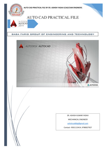
Chapter 1: Overview of V8 Functionality4. Uncheck the Models option. Since SHA is not currently calling for the use of Models,we’re going to turn that off for now.Notice that the icon disappears from the Primary toolbox.A Cool Tool:After right-clicking a toolbox, the List option will allow the user to toggle multiple toolson and off in one shot.Using View GroupsNotice the new View Groups dialog to the bottom left of the screen.A view group is a named collection of the eight MicroStation view windows which allows you to set upyour view to display different preferences including number of open view windows, window size, vieworientation, view attributes and level display. Each view group is associated with a model making it easyto access and navigate through different models.This example has 3 view groups; Default, Border Only and Title Block.1. Click on the arrow next to the Default view group.2. Select the Border Only view group.Notice the change in the MicroStation levels (the Index Sheet text is turned off) as well as the viewattributes (the Line Weights are turned off).3. Select the Title Block view group.SHA V8 00036/5/20041-6
Chapter 1: Overview of V8 FunctionalityAgain, notice the change in the view. The text and line weights reappear as well as a second viewwindow with an enlarged view of the title block.Creating a View Group1. Open and resize additional view windows in the configuration you would like to use.2. In the View Groups window, click the Manage View Groups icon to invoke theManage View Groups dialog.3. Click the Create View Group icon.4. Complete the Name and Description fields.5. Click OK to create the new view group.AccuSnapAccuSnap provides tentative snap functionality, which may be used stand-alone or in combination withAccuDraw. It provides graphical assistance — a “smart” pointer — for identifying and snapping toelements. This automates the tentative snap process, virtually eliminating the need to press the tentativesnap button, thus reducing the number of “button presses” required during a design session.SHA V8 00036/5/20041-7
Chapter 1: Overview of V8 FunctionalityNote: The settings for AccuSnap may be adjusted or tuned off by selecting Snaps AccuSap fromthe MicroStation Settings pull down menu.One of the features of AccuSnap is the ability to automatically identify elements. This can eliminate adata point in certain tools. We will explore this with respect to the Delete Element tool.We don’t need the consultant logo box and text in this example so we are going to delete it.1. Select the Delete Element tool from the main toolbox.2. Float the mouse cursor over the PLACE CONSULTANT LOGO HERE text in the lowerleft hand corner of the design file and notice that the element automatically highlights.3. With the block highlighted, click a data point to delete the block. N
combine hands-on learning, visual aids and lecture. Course Objectives When you complete this course, you will understand the following: New features in MicroStation V8 How the new V8 features relate to the MDSHA CAD Standards How to use Bar Menu to place MicroStation elements How to compose a display How to plot a display