Transcription
4.5 Slope ProtectionGeneral InformationRelatively flat areas—those with slopes of 2 percent or less—can be treated to a largeextent through controlled clearing and grading, mulch, and temporary or permanent seed.Slopes greater than that, however, require more attention to sheet runoff volume and themanagement of areas where flows converge and are transported to downstream receivingwaters. Sediment barriers, rolled erosion control products, and greater attention to downslopedrainage are usually needed on slopes, especially those that are steep and long.This section addresses erosion protection and sediment control approaches specifically forslopes. In general slopes that are long (50 feet or more), steep (5 percent plus), and composedof highly erodible (silty) soils require more protection that shorter, flatter slopes of lesserodible soil. Slope protection approaches discussed below include erosion control blanketsand turf reinforcement mats, which can also be used for ditch protection, surface roughening,slope drains, gabion structures, and cellular mats.Approximate Slope ConversionsApproximate slope conversions (horizontal:vertical)PercentSlope 4º10%10:16ºSlope Protection BasicsProtecting slopes from erosion requires several actions that must be taken together. No singleapproach will be successful, especially if the slope is steep or has highly erodible soils (seetable). Use one or more of the following actions to reduce erosion on slopes:Divert upland runoff—Install a berm or channel above the slope to divert upland rain runoffaround the bare soil area or a stable ditch to move upland flows through the site withoutpicking up additional sediment.Control slope runoff—If slopes are broken up into benches or steps, runoff can be collectedand diverted along berms or in channels to pipe or channel slope drains.Till seedbed or condition the soil—Dozer tracks up and down slopes help hold soil in place.See the table below for information on how the condition of the soil surface (e.g., compacted,tracked) can increase or decrease erosion.Seed and mulch—This is the best and cheapest protection by far. See temporary andpermanent seeding Fact Sheets for details on seed types, application rates, and mulch,blanket, and mat products.Silt fence or brush barrier—These should be installed at the toe of the slope, and every 75 to125 feet apart on long slopes.Retaining wall—Extremely steep slopes can be leveled out and shortened into two or moresteps or benches by installing retaining walls of rock, brick, block, wood, logs, or othermaterial. If rock layers are present along the slope, use these to establish firm benches in astair-step pattern.Blankets or armoring—Long slopes (greater than 100 feet) exceeding 3H:1V with highlyerodible soils need to be protected with erosion control blankets or turf reinforcement mats.Rock mulch and lined downdrain channels might be needed on steep slopes to control gullying.Kentucky Construction Site BMP Planning and Technical Specifications Manual75
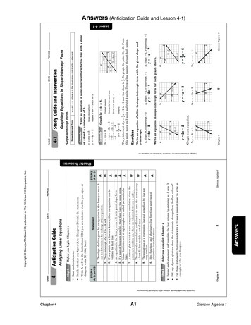
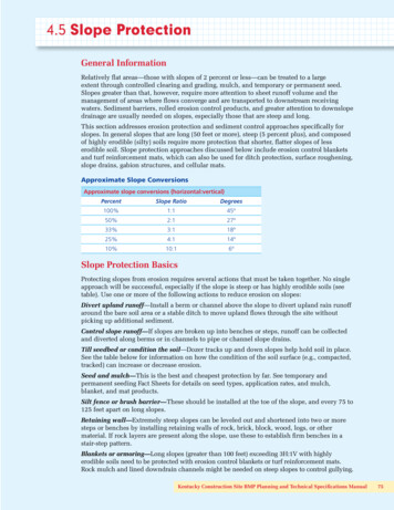
Soil Conditions vs. ErosionSoil Conditions vs. ErosionIf soil is:Erosion will be:Compacted and smooth30 percent moreTracks across slopes20 percent moreTracks up & down slopes10 percent lessRough and irregular10 percent lessRough & loose to 12" deep20 percent lessSlope Angle and Soil Type vs. ErodibilitySlope angleErodibilitySoil type50%40%30%20%15%10%5% 5%Very highSiltSilty sandClayey sandOrganic soilClaysSilty gravelSandGravelVery LowThe value of seed on a slope: the left (seeded) section shows almost no erosion; right side rills are quickly becominggullies. Seed and mulch slopes as soon as final grade is established for best results. Bare areas must be seeded ormulched within 14 days if no work is planned during the next week.76Technical Specifications for BMPs
4.5 Slope Protection4.5.1 Silt FenceSilt fencing is commonly used to pond,settle, and filter sediment from sheetrunoff. Install at proper spacing onslopes; set back from slope toe to allowfor maintenance. Make sure fencing istrenched in properly and stakes are onthe downhill side. Inspect frequentlyto detect and address bypasses,undercutting, and overtopping.DefinitionA silt fence is a temporary sediment barrier consisting of filter fabric entrenched into thesoil and attached to supporting posts. Silt fences are downhill from bare soil areas andare installed with a trencher or by a slicing machine to prevent against common silt fencefailures.PurposeSilt fences are common sediment control devices. Silt fencing should be installed wheresediment-laden water can pond, thus allowing the sediment to fall out of suspension andseparate from the runoff. Runoff will also bleed through the silt fence fabric, providingphysical filtering for larger sediment particles. Reasons for the high failure rate ofimproperly designed (located) and installed silt fence include Improper placement on the site Allowing excessive drainage area to the silt fence structure Shallow trenches with little or no soil compaction Inadequate attachment to posts Failure to maintain the silt fence after installation Installing silt fence along property boundaries, producing concentrated runoffDesign CriteriaSilt fencing must be installed only where water can pond. Specify silt fencing downgradientfrom bare soil areas, installed on the contour if possible, with the ends turned up to preventbypassing. Provide adequate setbacks from slope toe for routine maintenance and access.Silt fencing can be used where Non-concentrated sheet flow will occur Protection of adjacent property or nearby surface waters is required The size of the drainage area is no more than 1/4 acre per 100 linear feet of silt fence The maximum flow path length above the barrier is 100 feet for slopes less than 2percent, and 50 feet for slopes up to 10 percentKentucky Construction Site BMP Planning and Technical Specifications Manual77
The maximum slope gradient above the barrier is 2H:1V Silt fencing can be used in flat, short swales (i.e., slope is less than 2 percent; lengthis less than 200 feet) that drain less than 2 acres, if silt fencing is spaced every 50 feet. Reinforced silt fence must be required when the contributing slope is longer than 100feet and greater than 3 percent and the design life of the silt fence is greater than 6months.Silt Fence Spacing on Long SlopesLand SlopeMax. Slope Distance3% – 5%100 ft.5% – 10%75 ft.10% – 20%50 ft.20% – 50%25 ft.Silt fencing should not be used Around the perimeter of the construction site, unless J-hooks are used. Longcontinuous runs of silt fence will divert and concentrate sediment-laden runoff andalmost certainly result in failure. A good general rule is to drain no more than 1/3acre of disturbed area into each discrete J-hook; In ditches, channels, or streams. Silt fences cannot handle the volumes generatedby concentrated channel flows. When installed across a concentrated flow path,undercutting or end cutting of the fence often occurs, or the fence is pushed over bythe force of the flow.Construction SpecificationsSilt fences have a useful life of one season. Their principal mode of action is to slow andpond the water and allow soil particles to settle with some minor filtration through thefabric. Silt fences are not designed to withstand high heads of water, and therefore shouldbe located where only shallow pools (i.e., 1.5 feet or less) can form. Their use is limited tosituations in which sheet or overland flows are expected. Dig a trench on the contour at least 6 inches wide and 6 inches deep below the areato be treated, taking care to install J-hooks where flows will travel along the silt fence.Turn fence ends uphill to trap potential bypasses as needed. If posts are already attached to fabric, position the fencing so the posts are installedon the downhill side of the fabric. Drive posts to a depth of 1 foot below the bottom ofthe trench, against downslope trench wall for extra support. Posts for all silt fencingare spaced 6 feet apart. Push fabric into the trench, and spread fabric along trench bottom and sides; backfillthe trench and compact the soil. A preferred installation technique in deep, easilyworked soils with minimal rock content involves static slicing of the fence into theground with a chisel-plow implement such as the Tommy Silt Fence Machine orequivalent. The filter fabric is wire-tied directly to the posts with three diagonal ties. The height of a silt fence must be 18 inches minimum and 30 inches maximum.Sediment storage height and ponding height must not exceed 18 inches. Silt fences placed at the toe of a slope must be set at least 6 feet back from the toe toincrease ponding volume and provide room for maintenance.78Technical Specifications for BMPs
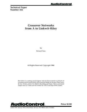
Inspection and MaintenanceAll sediment barriers should be placed downgradient from bare areas to be treated. Theends of the barrier should be turned uphill or otherwise configured to prevent end-aroundbypasses. Inspect fence for proper installation and compaction by pulling up on the fence whilekicking the toe of the fabric. If the fence comes out of the ground, do not accept theinstallation. If there are long, linear runs of silt fence without J-hooks, do not accept theinstallation. Silt fences and filter barriers must be inspected weekly and after each storm of greaterthan one-half inch. Any required repairs must be made immediately. Sediment should be removed when it reaches 1/3 height of the fence or 18 inchesmaximum. The removed sediment must be spread and vegetated or otherwise stabilized so that itdoes not result in muddy runoff to nearby ditches or surface waters. Silt fences must be removed when they have served their useful purpose, but notbefore the upslope area has been permanently stabilized (e.g., vegetated) and anysediment stored behind the silt fence has been removed. Silt fences and othertemporary controls must be removed before project close-out.Install silt fencing on the contour, with the endsturned uphill to trap muddy runoff and preventbypasses. Remove silt fences when grass isestablished.Make sure silt fence fabric istrenched in and is upslope ofstakes. Leave room between thefencing and the upgradient slope forremoving accumulated sediment.Do not use silt fencing inareas of concentrated flows.For best results, triple-seedditches and line with erosioncontrol blankets.Kentucky Construction Site BMP Planning and Technical Specifications Manual79
Use several short lengths of silt fence and J-hooks to interceptconverging runoff in critical areas, such as property corners.This can help relieve stress and prevent failure at the corners.Silt fence installed backwards—note that stakes are on the uphill,rather than downhill, side of the fabric. Ponding flows againstthis fence will push the fabric away from the stakes, causingfailure and releasing sediment to the small stream on the right.Use multiple silt fencesat proper spacing (seetable) to protect long,unvegetated slopes. Fencesprovide only temporaryprotection and can beremoved when the area isseeded and mulched.Silt fence is functioning well, but needsmaintenance. Set fences back from the toeof the slope, to allow room for sedimentto accumulate and maintenance.Good installation of “super” (i.e.,wire reinforced) silt fence. Notethat wire is installed betweenthe fabric and stakes, andprovides a web of support as theponded flow pushes against thefabric. Also, note the grass stripbetween the bare area and thefence, which helps to slow andfilter flows before ponding alongthe fence line.80Technical Specifications for BMPs
Kentucky Construction Site BMP Planning and Technical Specifications Manual81
82Technical Specifications for BMPs
Kentucky Construction Site BMP Planning and Technical Specifications Manual83
84Technical Specifications for BMPs
Kentucky Construction Site BMP Planning and Technical Specifications Manual85
4.5 Slope Protection4.5.2 Brush, Rock, and OtherSediment BarriersIf rock will be used at the site eventually,it could be beneficial to have it deliveredearly for use as a sediment barrier in thevicinity of its final use. Other sedimentbarriers include brush cleared fromthe site, fiber (log) rolls, and othercommercial products.DefinitionBrush, rock, and other commercial barriers can be used as a temporary sediment barrierinstead of a silt fence.PurposeThe purpose of any sediment barrier is to provide a place where sediment-laden water canpond, thus allowing the sediment to fall out of suspension and separate from the runoff.Design CriteriaSediment barriers should be installed where non-concentrated sheet flow will occur. Theyshould not be used in ditches, channels, or streams. Sediment barriers are usually placed afew feet beyond the toe of a slope, or across long slopes at specific intervals. When placingsediment barriers, consider materials on hand that might be used (e.g., brush cleared fromthe site, shot rock) during initial clearing and grading work. Silt fences or commercialsediment barrier products should be sited far enough away from the toe of the slope toallow for maintenance (i.e., access by a small loader, truck). There are several other factorsto consider in placing silt fences, rock sediment filters, or other commercial sedimentbarriers: Place filters on downhill edge of bare soil areas. Make sure the filter catches all the muddy runoff. Turn the ends of the barrier uphill to prevent bypasses The goal is to pond runoff, to filter and settle it out. Install multiple sediment filters on long slopes. Spacing on long slopes is every 60 to 110 feet. Put filters across slopes, on the contour (level).Placement criteria are similar to those specified for silt fences (see the preceding section).86Technical Specifications for BMPs
Construction SpecificationsBrush cleared from the site can make an excellent sediment filter if it is properly placed andbuilt up well. Brush barriers are installed on the contour and are 2–5 feet high and 4–10feet wide at the base. They should be walked down with a loader or dozer to compress thematerial.A rock berm can also provide an effective and low-maintenance sediment barrier. Rockberms placed in concentrated flow areas function as sediment traps (for more informationon that type of application, see Section 4.7.1). Longer rock berms constructed as sheetrunoff sediment barriers should be 18" to 30" in height and consist of stone 2–6 inches indiameter.Fiber rolls and other commercial products made from coconut fiber, plastic, wood shavings,compost, or other material can also be used as sediment barriers on slopes flatter than 10:1.Follow manufacturers’ installation instructions and ensure that sediment filter spacing onslopes is correct.For information on locating and installing rock or commercial barriers, see constructionspecifications for silt fences in the preceding section.Inspection and MaintenanceSediment barriers should be inspected weekly and after each rainfall of greater than onehalf inch. Look for signs of bypassing along the sides, undercutting below the barrier,overtopping, or blowout. Make required repairs immediately. For recurring blowouts,consider pulling some upland muddy flow away and trapping it before it can reach theblowout area. Use a J-hook or other strategically placed barrier.Remove sediment when it reaches 1/3 height of the fence or 9 inches maximum. Spread theremoved sediment and vegetate or otherwise stabilize it.Remove sediment barriers when they have served their useful purpose but not before theupslope area has been permanently stabilized (i.e., vegetated or otherwise covered) and anysediment stored behind the barrier has been removed.Brush cleared from the site used as a temporarydownslope sediment barrier. Make sure barrierintercepts and ponds up muddy runoff. Removewhen grass is established.Fiber rolls provide excellent protection forresidential lots. They can be stepped overand driven over, and are preferable to siltfencing in tight areas.Super (wirereinforced) silt fencein the foreground,supplementedby rock sedimentbarrier (background).Use rock or othersediment barrierswhen appropriate.Kentucky Construction Site BMP Planning and Technical Specifications Manual87
4.5 Slope Protection4.5.3 Erosion Control Blankets andTurf Reinforcement MatsErosion control blankets provide excellentprotection for seedbeds, especiallyon slopes and in areas of high winds.Blankets can be used to stabilize ditcheswith flatter slopes. For steeper ditches,use turf reinforcement mats.DefinitionTemporary erosion control blankets (ECBs) and permanent turf reinforcement mats (TRMs),known generally as rolled erosion control products, are single or multiple layer sheetscomposed of natural or synthetic material that is woven, sewn, bonded, or otherwisemanufactured for placement on bare soil slopes or flow channels. They have beendescribed as a temporary, degradable products composed of processed natural or polymerfibers mechanically, structurally, or chemically bound together to form a continuous matrixto provide erosion control and facilitate vegetation establishment.PurposeECBs are used to temporarily stabilize and protect disturbed soil from raindrop impactand surface erosion, to increase infiltration, decrease compaction and soil crusting, andto conserve soil moisture. Mulching with ECBs will increase the germination rates forgrasses and legumes and promote vegetation establishment. ECBs also protect seeds frompredators, reduce desiccation and evaporation by insulating the soil and seed environment.Some types of ECBs and turf reinforcement mats are specifically designed to stabilizechannelized flow areas. These blankets and mats can aid the establishment of vegetationin waterways and increase the maximum permissible velocity of the given channel byreinforcing the soil and vegetation to resist the forces of erosion during runoff events.Stems, roots and rhizomes of the vegetation become intertwined with the mat, reinforcingthe vegetation and anchoring the mat.Design CriteriaAll final slopes 2H:1V or steeper should be protected with an ECB. ECBs are constructedof various degradable organic / synthetic fibers that are woven, glued or structurally boundwith nettings or meshes. The most widely used ECBs are made from straw, wood excelsior,coconut, polypropylene or a combination thereof stitched or glued together or into orbetween biaxially oriented process nettings or woven natural fiber nettings. They are usefulon sites requiring greater, more durable or longer-lasting erosion protection. Applicationsinclude gradual to steep slopes, low to moderate flow channels and low-impact shorelinings. Because these degradable materials are designed to provide temporary erosionprotection, they generally are limited to areas where natural, unreinforced vegetation alonewill provide long-term soil stabilization.88Technical Specifications for BMPs
The functional longevity of ECBs can be varied to accommodate the site-specificrequirements. Some ECBs are designed to last for less than 3 months for use in highmaintenance areas that will be mowed soon after turf establishment, while others are madeto provide longer-lasting protection in applications requiring erosion control/mulch for upto 3 years.TRMs consist of various UV-stabilized, synthetics fibers and filaments processed intopermanent, high-strength, 3-D matrices. Common examples include cuspated polyethylenemeshes heat-bonded together, extruded monofilaments of nylon or PVC heat-bonded attheir intersections, and crimped polyolefin fibers and other materials mechanically stitchedbetween high-strength nettings. TRMs are designed for permanent and critical hydraulicapplications such as drainage channels, where design discharges exert velocities and shearstresses that exceed the limits of mature, natural vegetation. Though some TRMs alsocontain degradable components to supplement their permanent structures, all TRMs bydefinition have a permanent three dimensional structure with high-tensile strength thatfunctions as a matrix for entangling plant roots, stems and soils.Together, the TRM and vegetation form a continuous composite—a unified, living mat.This synergism increases root systems’ lateral strength, reducing plant dislodgement underhigh-velocity, high-shear stress flows. The TRM’s permanent structure also functions toconsolidate and protect the soils in which the plants are anchored, preventing soil frombeing stripped out of the vegetative cover and the resulting weakening of the root support.TRMs are often used in situations where the green alternative is preferred to hard armor.Select the ECB or TRM according to slope steepness and length and expected sheer stress ifapplication is to a flow channel or ditch. If the area will be mowed eventually, consider thespecified breakdown time for ECB plastic netting. TRM areas should not be mowed untilvegetation is well established, and then as little (or as high) as possible. The table at the endof this section provides guidance on the application of various blankets and mats. An ECBor mat should be used in all drainage channels with slopes of 2 percent or more, and in thefollowing conditions: Slopes and disturbed soils where mulch must be anchored and other methods suchas crimping or tackifying are not feasible nor adequate Steep, long slopes, generally steeper than 3H:1V and longer than 50 feet Slopes where erosion hazards are high Critical slopes adjacent to sensitive areas such as streams and wetlands Disturbed soil areas where planting is likely to be slow in providing adequateprotective coverTake care to choose the type of blanket or matting that is appropriate for the specificneeds of a project. There are many soil stabilization products available today, and itis very difficult to cover all the advantages, disadvantages and specifications of all themanufactured blankets and mats. Therefore, as with many erosion control type products,there is no substitute for a thorough understanding of manufacturer’s instructions andrecommendations and a site visit by a designer or plan reviewer to verify a product’sappropriateness.Construction SpecificationsECBs and TRMs are designed to cover germinating seed and provide a protective matrixthat helps anchor seed to the underlying soil. (Note: a few TRMs have seed embeddedin the mat.) This requires complete, uniform contact with the soil, solid stapling, andattention to topslope anchoring, overlaps, and other installation details, as noted below.Kentucky Construction Site BMP Planning and Technical Specifications Manual89
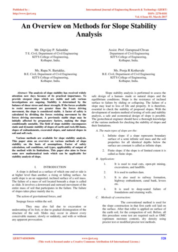
Site PreparationProper site preparation is essential to ensure complete contact of the protection matting withthe soil. Grade and shape area of installation Remove all rocks, roots, clods, vegetative, or other obstructions so that the installedblankets or mats will have direct contact with the soil Prepare seedbed by loosening 2–3 inches of topsoil above final grade Incorporate amendments, such as lime and fertilizer, into soil according to soil testand the seeding planSeedingSeed the area before installing blanket for erosion control and revegetation. Seeding aftermat installation is sometimes specified for turf reinforcement application—check themanufacturer’s instructions. When seeding before blanket installation, reseed all check slotsand other areas disturbed during installation.Where soil filling is specified for certain TRMs, seed the matting and the entire disturbedarea after installation and before filling the mat with soil. Follow the manufacturer’sinstructions to ensure proper installation.AnchoringU-shaped wire staples, metal geotextile stake pins, or triangular wooden stakes can be usedto anchor ECBs and TRMs to the ground surface. Wire staples should be a minimum of 11gauge. Metal stake pins should be 3/16 inch diameter steel with a 1.5 inch steel washer atthe head of the pin. Wire staples and metal stakes should be driven flush to the soil surface.All anchors should be 6–8 inches long and have sufficient ground penetration to resistpullout. Longer anchors might be required for loose soils. Use biodegradable composite orwooden stakes where dislodged metal staples or stakes might cause extreme hazards, suchas near airport runways or areas where future mowing might cause risk.Installation on SlopesBegin at the top of the slope and anchorthe blanket in a 6 inch deep by 6 inch widetrench. Backfill trench and tamp earth firmly. Unroll blanket downslope in thedirection of the water flow. The edges of adjacent parallel rollsmust be overlapped at least 3 inchesand be stapled through the overlappedarea at least every 3 feet on slopes lessthan 4H:1V and every 2 feet on steeperslopes. When blankets must be spliced, placeuphill blanket end over downhillblanket (shingle style) with 6-inchoverlap. Staple through overlappedarea, approximately 12 inches apart.Install blankets and mats vertically on long slopes. Trenchand staple top section, overlap sides 3 to 6 inches.Follow manufacturer’s directions regarding stapling andslope limitations. For areas that will be mowed, specifyblankets without plastic netting or material designed todecompose within 6 months. Lay blankets and mats loosely and maintain direct contact with the soil—do notstretch. Ensure good, consistent, direct soil contact. ECBs and TRMs must be stapled sufficiently to anchor the blanket and maintain contactwith the soil. Staples must be placed down the center and staggered with the staplesplaced along the edges. Steep slopes (1H:1V to 2H:1V) require at least two staples persquare yard. Moderate slopes (2H:1V to 3H:1H) require 1-2 staples per square yard (1staple 3 every feet on center). Gentle slopes require one staple per square yard.90Technical Specifications for BMPs
Installation in ditches and channelsDig initial anchor trench 12 inches deepand 6 inches wide across the channel (i.e.,parallel to the flow direction) at the lowerend of the project area. Excavate intermittent check slots, 6inches deep and 6 inches wide acrossthe channel at 25–30 foot intervalsalong the channel. Cut longitudinal channel anchorslots 4 inches deep and 4 inches widealong each side of the installation toDitch installation for blanket or mat. Triple-seed ditch, trenchin upslope blanket sides, and staple down securely. Lay ditchbury edges of matting. These anchorsections horizontally, lapping upslope sections over downslopeslots will mark the upper elevationsections. Use plenty of staples below the water line.of the ECB or TRM along the channelside slopes, and should be above the 10 year, 24-hour peak flow line. Wheneverpossible extend the ECB or TRM 1 foot or more above the crest of channel side slopes. Beginning at the downstream end and in the center of the channel, place the initialend of the first roll in the anchor trench and secure with fastening devices at 1-footintervals. Note: Matting will initially be upside down in anchor trench. In the same manner, position adjacent rolls in the anchor trench, overlapping thepreceding roll a minimum of 6–8 inches. Secure these initial ends of mats with anchors at 1-foot intervals, backfill andcompact soil. Unroll the center strip of matting upstream. Stop at the next check slot or terminalanchor trench. Unroll adjacent mats upstream in similar fashion, maintaining a 3-inch overlap. Fold and secure all rolls of matting snugly into all transverse check slots. Lay the matin the bottom of the slot then fold back against itself. Anchor through both layers ofmat at 1-foot intervals, then backfill and compact the soil. Continue rolling all matwidths upstream to the next check slot or terminal anchor trench. Alternate method for noncritical installations: place two rows of anchors on 6-inchcenters at 25–30 feet intervals in lieu of excavated check slots. Shingle-lap the splicedends by a minimum of 1 foot with the upstream mat on top (to prevent uplifting bywater) or begin new rolls in a check slot. Anchor the overlapped area by placing tworows of anchors, 1 foot apart on 1-foot intervals. Place the edges of outside mats in previously excavated longitudinal slots, anchorthem using the prescribed staple pattern, then backfill and compact the soil. Anchor, fill, and compact the upstream end of the mat in a 12-inch by 6-inch terminaltrench. Secure the mat to the ground using U-shaped wire staples, geotextile pins, or woodenstakes. Seed and fill the TRM with soil, if specified. Soil filling (if specified for TRM) After seeding, spread and lightly rake one-half to three-quarter inch of fine topsoilinto the mat apertures to completely fill the mat thickness. Use the backside of a rakeor other flat implement. Spread topsoil using lightweight loader, backhoe, or otherpower equipment. Avoid making sharp turns with the equipment.Kentucky Construction Site BMP Planning and Technical Specifications Manual91
92Technical Specifications for BMPsProcessed degradable natural and/or polymer fibersmechanically bound together between two rapidlydegrading, synthetic or natural fiber nettings.Double-net ECBsMulch ControlNetsNetless RolledECBsSingle-net ECBs& Open WeaveTextilesDouble-net ECBs2.B2.C2.DProductDescription2.AType2:1 (H:V)An erosion control blanket composed of processed3:1 (H:V)degradable natural or polymer fibers mechanically boundtogether by a single degradable synthetic or natural fibernetting to form a continuous matrix or an open weave textilecomposed of processed degradable natural or polymer yarnsor twines woven into a continuous matrix.Natural and/or polymer fibers mechanically interlocked and/ 4:1 (H:V)or chemically adhered together to form a RECP.Processed degradable natural and/or polymer fibersmechanically bound together between two degradable,synthetic or natural fiber nettings. 0.20 @ 2:1 0.15 @ 3:1 0.20 @ 2:1 0.15 @ 3
Percent Slope Ratio Degrees 100% 1:1 45º 50% 2:1 27º 33% 3:1 18º 25% 4:1 14º 10% 10:1 6º Slope Protection Basics Protecting slopes from erosion requires several actions that must be taken together. No single approach will be successful, especially if the