Transcription
Chapter5Geometric Dimensioning and TolerancingWalter M. StitesPaul DrakeWalter M. StitesAccraTronics Seals Corp.Burbank, CaliforniaWalter M. Stites is a graduate of California State University, Northridge. His 20-year tenure atAccraTronics Seals Corp began with six years in the machine shop, where he performed every task fromoperating a hand drill press to making tools and fixtures. Trained in coordinate measuring machine(CMM) programming in 1983, he has since written more than 1,000 CMM programs. He also performsproduct design, manufacturing engineering, and drafting. In 12 years of computer-assisted drafting,he’s generated more than 800 engineering drawings, most employing GD&T. He has written variousmanuals, technical reports, and articles for journals. Mr. Stites is currently secretary of the ASME Y14.5subcommittee and a key player in the ongoing development of national drafting standards.5.1Introducing Geometric Dimensioning and Tolerancing (GD&T)When a hobbyist needs a simple part for a project, he might go straight to the little lathe or milling machinein his garage and produce it in a matter of minutes. Since he is designer, manufacturer, and inspector all inone, he doesn’t need a drawing. In most commercial manufacturing, however, the designer(s),manufacturer(s), and inspector(s) are rarely the same person, and may even work at different companies,performing their respective tasks weeks or even years apart.A designer often starts by creating an ideal assembly, where all the parts fit together with optimaltightnesses and clearances. He will have to convey to each part’s manufacturer the ideal sizes and shapes,or nominal dimensions of all the part’s surfaces. If multiple copies of a part will be made, the designer mustrecognize it’s impossible to make them all identical. Every manufacturing process has unavoidable variations that impart corresponding variations to the manufactured parts. The designer must analyze hisentire assembly and assess for each surface of each part how much variation can be allowed in size, form,5-1
5-2Chapter Fiveorientation, and location. Then, in addition to the ideal part geometry, he must communicate to themanufacturer the calculated magnitude of variation or tolerance each characteristic can have and stillcontribute to a workable assembly.For all this needed communication, words are usually inadequate. For example, a note on the drawingsaying, “Make this surface real flat,” only has meaning where all concerned parties can do the following: Understand English Understand to which surface the note applies, and the extent of the surface Agree on what “flat” means Agree on exactly how flat is “real flat”Throughout the twentieth century, a specialized language based on graphical representations andmath has evolved to improve communication. In its current form, the language is recognized throughoutthe world as Geometric Dimensioning and Tolerancing (GD&T).5.1.1What Is GD&T?Geometric Dimensioning and Tolerancing (GD&T) is a language for communicating engineering designspecifications. GD&T includes all the symbols, definitions, mathematical formulae, and application rulesnecessary to embody a viable engineering language. As its name implies, it conveys both the nominaldimensions (ideal geometry), and the tolerances for a part. Since GD&T is expressed using line drawings,symbols, and Arabic numerals, people everywhere can read, write, and understand it regardless of theirnative tongues. It’s now the predominant language used worldwide as well as the standard languageapproved by the American Society of Mechanical Engineers (ASME), the American National StandardsInstitute (ANSI), and the United States Department of Defense (DoD).It’s equally important to understand what GD&T is not. It is not a creative design tool; it cannotsuggest how certain part surfaces should be controlled. It cannot communicate design intent or anyinformation about a part’s intended function. For example, a designer may intend that a particular borefunction as a hydraulic cylinder bore. He may intend for a piston to be inserted, sealed with two Buna-NO-rings having .010" squeeze. He may be worried that his cylinder wall is too thin for the 15,000-psipressure. GD&T conveys none of this. Instead, it’s the designer’s responsibility to translate his hopesand fears for his bore—his intentions—into unambiguous and measurable specifications. Such specifications may address the size, form, orientation, location, and/or smoothness of this cylindrical part surface as he deems necessary, based on stress and fit calculations and his experience. It’s these objectivespecifications that GD&T codifies. Far from revealing what the designer has in mind, GD&T cannot evenconvey that the bore is a hydraulic cylinder, which gives rise to the Machinist’s Motto.Mine is not to reason why;Mine is but to tool and die.Finally, GD&T can only express what a surface shall be. It’s incapable of specifying manufacturingprocesses for making it so. Likewise, there is no vocabulary in GD&T for specifying inspection or gagingmethods. To summarize, GD&T is the language that designers use to translate design requirements intomeasurable specifications.5.1.2Where Does GD&T Come From?—ReferencesThe following American National Standards define GD&T’s vocabulary and provide its grammatical rules.
Geometric Dimensioning and Tolerancing5-3 ASME Y14.5M-1994, Dimensioning and Tolerancing ASME Y14.5.1M-1994, Mathematical Definition of Dimensioning and Tolerancing PrinciplesHereafter, to avoid confusion, we’ll refer to these as “Y14.5” and “the Math Standard,” respectively(and respectfully). The more familiar document, Y14.5, presents the entire GD&T language in relativelyplain English with illustrated examples. Throughout this chapter, direct quotations from Y14.5 will appearin boldface. The supplemental Math Standard expresses most of GD&T’s principles in more precise mathterminology and algebraic notation—a tough read for most laymen. For help with it, see Chapter 7.Internationally, the multiple equivalent ISO standards for GD&T reveal only slight differences betweenISO GD&T and the US dialect. For details, see Chapter 6.Unfortunately, ASME offers no 800 number or hotline for Y14.5 technical assistance. Unlike computer software, the American National and ISO Standards are strictly rulebooks. Thus, in many cases, forASME to issue an interpretation would be to arbitrate a dispute. This could have far-reaching legalconsequences. Your best source for answers and advice are textbooks and handbooks such as this. Asmembers of various ASME and ISO standards committees, the authors of this handbook are brimmingwith insights, experiences, interpretations, preferences, and opinions. We’ll try to sort out the few usefulones and share them with you. In shadowboxes throughout this chapter, we’ll concoct FAQs (frequentlyasked questions) to ourselves. Bear in mind, our answers reflect our own opinions, not necessarily thoseof ASME or any of its committees.In this chapter, we’ve taken a very progressive approach toward restructuring the explanations andeven the concepts of GD&T. We have solidified terminology, and stripped away redundancy. We’ve triedto take each principle to its logical conclusion, filling holes along the way and leaving no ambiguities. Asyou become more familiar with the standards and this chapter, you’ll become more aware of our emphasison practices and methodologies consistent with state-of-the-art manufacturing and high-resolution metrology.FAQ: I notice Y14.5 explains one type of tolerance in a single paragraph, but devotes pages andpages to another type. Does that suggest how frequently each should be used?A:No. There are some exotic principles that Y14.5 tries to downplay with scant coverage, butmostly, budgeting is based on a principle’s complexity. That’s particularly true of this handbook. We couldn’t get by with a brief and vague explanation of a difficult concept just because it doesn’t come up very often. Other supposed indicators, such as what questionsshow up on the Certification of GD&T Professionals exam, might be equally unreliable. Throughout this chapter, we’ll share our preferences for which types of feature controls to use invarious applications.FAQ: A drawing checker rejected one of my drawings because I used a composite feature controlframe having three stacked segments. Is it OK to create GD&T applications not shown inY14.5?A:Yes. Since the standards can neither discuss nor illustrate every imaginable application ofGD&T, questions often arise as to whether or not a particular application, such as that shownin Fig. 5-127, is proper. Just as in matters of law, some of these questions can confound theexperts. Clearly, if an illustration in the standard bears an uncanny resemblance to your ownpart, you’ll be on pretty solid ground in copying that application. Just as often, however, thestandard makes no mention of your specific application. You are allowed to take the explicitrules and principles and extend them to your application in any way that’s consistent with allthe rules and principles stated in the standard. Or, more simply, any application that doesn’t
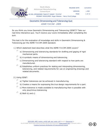
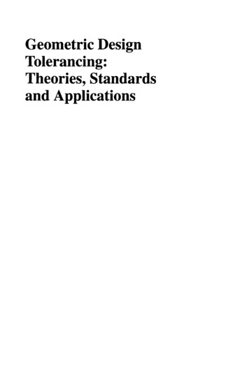
5-4Chapter Fiveviolate anything in the standard is acceptable. That’s good news for a master practitionerwho’s familiar with the whole standard. Throughout this chapter we’ll try to help novices byincluding “extension of principle” advice where it’s appropriate.FAQ: I’ve found what seem to be discrepancies between Y14.5 and the Math Standard. How canthat be? Which standard supersedes?A:5.1.3You’re right. There are a couple of direct contradictions between the two standards. Like anycontemporary “living” language, GD&T is constantly evolving to keep pace with our modernworld and is consequently imperfect. For instance, Y14.5 has 232 pages while the MathStandard has just 82. You could scarcely expect them to cover the same material in perfectharmony. Yet there’s no clue in either document as to which one supersedes (they were issuedonly eight days apart). Where such questions arise, we’ll discuss the issues and offer ourpreference.Why Do We Use GD&T?When several people work with a part, it’s important they all reckon part dimensions the same. In Fig. 5-1,the designer specifies the distance to a hole’s ideal location; the manufacturer measures off this distanceand (“X marks the spot”) drills a hole; then an inspector measures the actual distance to that hole. All threeparties must be in perfect agreement about three things: from where to start the measurement, whatdirection to go, and where the measurement ends.As illustrated in Chapter 3, when measurements must be precise to the thousandth of an inch, theslightest difference in the origin or direction can spell the difference between a usable part and an expensive paperweight. Moreover, even if all parties agree to measure to the hole’s center, a crooked, bowed, oregg-shaped hole presents a variety of “centers.” Each center is defensible based on a different designconsideration. GD&T provides the tools and rules to assure that all users will reckon each dimension thesame, with perfect agreement as to origin, direction, and destination.It’s customary for GD&T textbooks to spin long-winded yarns explaining how GD&T affords moretolerance for manufacturing. By itself, it doesn’t. GD&T affords however much or little tolerance thedesigner specifies. Just as ubiquitous is the claim that using GD&T saves money, but these claims arenever accompanied by cost or Return on Investment (ROI) analyses. A much more fundamental reason forFigure 5-1 Drawing showing distance toideal hole location
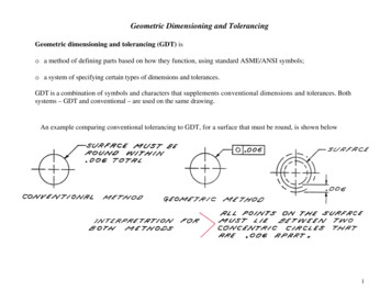
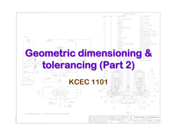
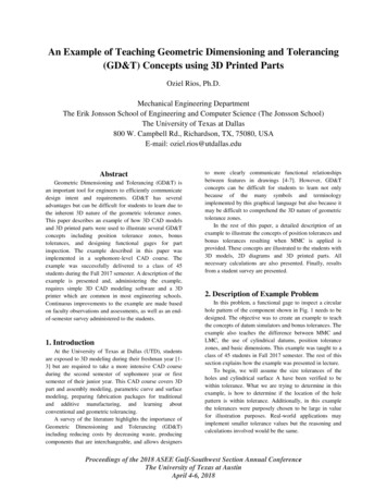
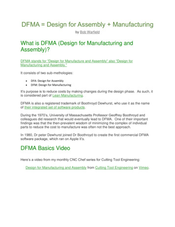
Geometric Dimensioning and Tolerancing5-5using GD&T is revealed in the following study of how two very different builders approach constructinga house.A primitive builder might start by walking around the perimeter of the house, dragging a stick in thedirt to mark where walls will be. Next, he’ll lay some long boards along the lines on the uneven ground.Then, he’ll attach some vertical boards of varying lengths to the foundation. Before long, he’ll have aframework erected, but it will be uneven, crooked, and wavy. Next, he’ll start tying or tacking palmbranches, pieces of corrugated aluminum, or discarded pieces of plywood to the crude frame. He’ll overlapthe edges of these flexible sidings 1-6 inches and everything will fit just fine. Before long, he’ll have theserviceable shanty shown in Fig. 5-2, but with some definite limitations: no amenities such as windows,plumbing, electricity, heating, or air conditioning.Figure 5-2 House built without all of theappropriate toolsA house having such modern conveniences as glass windows and satisfying safety codes requiresmore careful planning. Materials will have to be stronger and more rigid. Spaces inside walls will have tobe provided to fit structural members, pipes, and ducts.To build a house like the one shown in Fig. 5-3, a modern contractor begins by leveling the groundwhere the house will stand. Then a concrete slab or foundation is poured. The contractor will make theslab as level and flat as possible, with straight, parallel sides and square corners. He will select thestraightest wooden plates, studs, headers, and joists available for framing and cut them to preciselyuniform lengths. Then he’ll use a large carpenter’s square, level, and plumb bob to make each framemember parallel or perpendicular to the slab.Why are such precision and squareness so important? Because it allows him to make accuratemeasurements of his work. Only by making accurate measurements can he assure that such prefabricatedFigure 5-3 House built using the correct tools
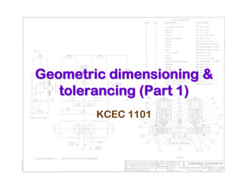
5-6Chapter Fiveitems as Sheetrock, windows, bathtubs, and air conditioning ducts will fit in the spaces between his framemembers. Good fits are important to conserve space and money. It also means that when electrical outletboxes are nailed to the studs 12" up from the slab, they will all appear parallel and neatly aligned. Remember that it all derives from the flatness and squareness of the slab.By now, readers with some prior knowledge of GD&T have made the connection: The house’sconcrete slab is its “primary datum.” The slab’s edges complete the “datum reference frame.” The woodenframing corresponds to “tolerance zones” and “boundaries” that must contain “features” such as pipes,ducts, and windows.Clearly, the need for precise form and orientation in the slab and framing of a house is driven by thefixtures to be used and how precisely they must fit into the framing. Likewise, the need for GD&T on a partis driven by the types and functions of its features, and how precisely they must relate to each other and/or fit with mating features of other parts in the assembly. The more complex the assembly and the tighterthe fits, the greater are the role and advantages of GD&T.Fig. 5-4 shows a non-GD&T drawing of an automobile wheel rotor. Despite its neat and uniformappearance, the drawing leaves many relationships between part features totally out of control. Forexample, what if it were important that the 5.50 bore be perpendicular to the mounting face? Nothing onthe drawing addresses that. What if it were critical that the 5.50 bore and the 11.00 OD be on the sameaxis? Nothing on the drawing requires that either. In fact, Fig. 5-5 shows the “shanty” that could be built.Although all its dimensions are within their tolerances, it seems improbable that any “fixtures” could fit it.Figure 5-4 Drawing that does not use GD&TIn Fig. 5-6, we’ve applied GD&T controls to the same design. We’ve required the mounting face to beflat within .005 and then labeled it datum feature A. That makes it an excellent “slab” from which we canlaunch the rest of the part. Another critical face is explicitly required to be parallel to A within .003. Theperpendicularity of the 5.50 bore is directly controlled to our foundation, A. Now the 5.50 bore can belabeled datum feature B and provide an unambiguous origin—a sturdy “center post”—from which the .515 bolt holes and other round features are located. Datum features A and B provide a very uniform andwell-aligned framework from which a variety of relationships and fits can be precisely controlled. Just as
Geometric Dimensioning and Tolerancing5-7Figure 5-5 Manufactured part thatconforms to the drawing without GD&T(Fig. 5-4)importantly, GD&T provides unique, unambiguous meanings for each control, precluding each person’shaving his own competing interpretation. GD&T, then, is simply a means of controlling surfaces moreprecisely and unambiguously.Figure 5-6 Drawing that uses GD&T
5-8Chapter FiveAnd that’s the fundamental reason for using GD&T. It’s the universal language throughout the worldfor communicating engineering design specifications. Clear communication assures that manufacturedparts will function and that functional parts won’t later be rejected due to some misunderstanding. Fewerarguments. Less waste.As far as that ROI analysis, most of the costs GD&T reduces are hidden, including the following: Programmers wasting time trying to interpret drawings and questioning the designers Rework of manufactured parts due to misunderstandings Inspectors spinning their wheels, deriving meaningless data from parts while failing to check criticalrelationships Handling and documentation of functional parts that are rejected Sorting, reworking, filing, shimming, etc., of parts in assembly, often in added operations Assemblies failing to operate, failure analysis, quality problems, customer complaints, loss of marketshare and customer loyalty The meetings, corrective actions, debates, drawing changes, and interdepartmental vendettas thatresult from each of the above failuresIt all adds up to an enormous, yet unaccounted cost. Bottom line: use GD&T because it’s the rightthing to do, it’s what people all over the world understand, and it saves money.5.1.4When Do We Use GD&T?In the absence of GD&T specifications, a part’s ability to satisfy design requirements depends largely onthe following four “laws.”1. Pride in workmanship. Every industry has unwritten customary standards of product quality, andmost workers strive to achieve them. But these standards are mainly minimal requirements, usuallypertaining to cosmetic attributes. Further, workmanship customs of precision aerospace machinistsare probably not shared by ironworkers.2. Common sense. Experienced manufacturers develop a fairly reliable sense for what a part is supposedto do. Even without adequate specifications, a manufacturer will try to make a bore very straight andsmooth, for example, if he suspects it’s for a hydraulic cylinder.3. Probability. Sales literature for modern machining centers often specifies repeatability within 2 microns (.00008"). Thus, the running gag in precision manufacturing is that part dimensions shouldnever vary more than that. While the performance of a process can usually be predicted statistically,there are always “special causes” that introduce surprise variations. Further, there’s no way to predictwhat processes might be used, how many, and in what sequence to manufacture a part.4. Title block, workmanship, or contractual (“boiler plate”) standards. Sometimes these provide clarification, but often, they’re World War II vintage and inadequate for modern high-precision designs. Anexample is the common title block note, “All diameters to be concentric within .005.”Dependence on these four “laws” carries obvious risks. Where a designer deems the risks too high,specifications should be rigorously spelled out with GD&T.
Geometric Dimensioning and Tolerancing5-9FAQ: Should I use GD&T on every drawing?A:Some very simple parts, such as a straight dowel, flat washer, or hex nut may not need GD&T.For such simple parts, Rule #1 (explained in section 5.6.3.1), which pertains to size limits, mayprovide adequate control by itself. However, some practitioners always use GD&T positionaltolerancing for holes and width-type features (slots and tabs). It depends primarily on howmuch risk there is of a part being made, such as that shown in Fig. 5-5, which conforms to allthe non-GD&T tolerances but is nevertheless unusable.FAQ: Can I use GD&T for just one or two selected surfaces on a drawing, or is it “all or nothing?”A:On any single drawing you can mix and match all the dimensioning and tolerancing methodsin Y14.5. For example, one pattern of holes may be controlled with composite positionaltolerance while other patterns may be shown using coordinate dimensions with plus andminus tolerances. Again, it depends on the level of control needed. But, if you choose GD&Tfor any individual feature or pattern of features, you must give that feature the full treatment.For example, you shouldn’t dimension a hole with positional tolerance in the X-axis, and plusand minus tolerance in the Y-axis. Be consistent. Also, it’s a good idea to control the form andorientational relationships of surfaces you’re using as datum features.FAQ: Could GD&T be used on the drawings for a house?A:Hmmm. Which do you need, shanty or chateau?5.1.5How Does GD&T Work?—OverviewIn the foregoing paragraphs, we alluded to the goal of GD&T: to guide all parties toward reckoning partdimensions the same, including the origin, direction, and destination for each measurement. GD&T achievesthis goal through four simple and obvious steps.1. Identify part surfaces to serve as origins and provide specific rules explaining how these surfacesestablish the starting point and direction for measurements.2. Convey the nominal (ideal) distances and orientations from origins to other surfaces.3. Establish boundaries and/or tolerance zones for specific attributes of each surface along with specificrules for conformance.4. Allow dynamic interaction between tolerances (simulating actual assembly possibilities) where appropriate to maximize tolerances.5.2Part FeaturesUp to this point, we’ve used the terms surface and feature loosely and almost interchangeably. To speakGD&T, however, we must begin to use the vocabulary as Y14.5 does.Feature is the general term applied to a physical portion of a part, such as a surface, pin, tab,hole, or slot.Usually, a part feature is a single surface (or a pair of opposed parallel plane surfaces) having uniformshape. You can establish datums from, and apply GD&T controls to features only. The definition impliesthat no feature exists until a part is actually produced. There are two general types of features: those thathave a built-in dimension of “size,” and those that don’t.
5-10Chapter FiveFAQ: Is a center line a feature?A:No, since a center line or center plane can never be a physical portion of a part.FAQ: Well, what about a nick or a burr? They’re “physical portions of a part,” right?A:True, but Y14.5 doesn’t mean to include nicks and burrs as features. That’s why we’ve added“having uniform shape” to our own description.FAQ: With transitions at tangent radii or slight angles, how can I tell exactly where one featureends and the adjacent feature begins?A:You can’t. The Math Standard points out, “Generally, features are well defined only in drawings and computer models.” Therefore, you are free to reckon the border between features atany single location that satisfies all pertinent tolerances.5.2.1Nonsize FeaturesA nonsize feature is a surface having no unique or intrinsic size (diameter or width) dimension to measure.Nonsize features include the following: A nominally flat planar surface An irregular or “warped” planar surface, such as the face of a windshield or airfoilA radius—a portion of a cylindrical surface encompassing less than 180 of arc lengthA spherical radius—a portion of a spherical surface encompassing less than 180 of arc lengthA revolute—a surface, such as a cone, generated by revolving a spine about an axis5.2.2Features of SizeA feature of size is one cylindrical or spherical surface, or a set of two opposed elements oropposed parallel surfaces, associated with a size dimension.A feature of size has opposing points that partly or completely enclose a space, giving the feature anintrinsic dimension—size—that can be measured apart from other features. Holes are “internal” featuresof size and pins are “external” features of size. Features of size are subject to the principles of materialcondition modifiers, as we’ll explain in section 5.6.2.1.“Opposed parallel surfaces” means the surfaces are designed to be parallel to each other. To qualifyas “opposed,” it must be possible to construct a perpendicular line intersecting both surfaces. Only then,can we make a meaningful measurement of the size between them. From now on, we’ll call this type offeature a width-type feature.FAQ: Where a bore is bisected by a groove, is the bore still considered a single feature of size, orare there two distinct bores?A:A similar question arises wherever a boss, slot, groove, flange, or step separates any twootherwise continuous surfaces. A specification preceded by 2X clearly denotes two distinctfeatures. Conversely, Y14.5 provides no symbol for linking interrupted surfaces. For example,an extension line that connects two surfaces by bridging across an interruption has no standardized meaning. Where a single feature control shall apply to all portions of an interruptedsurface, a note, such as TWO SURFACES AS A SINGLE FEATURE, should accompanythe specification.
Geometric Dimensioning and Tolerancing5.2.2.15-11Screw ThreadsA screw thread is a group of complex helical surfaces that can’t directly be reckoned with as a feature ofsize. However, the abstract pitch cylinder derived from the thread’s flanks best represents the thread’sfunctional axis in most assemblies. Therefore, by default, the pitch cylinder “stands in” for the thread asa datum feature of size and/or as a feature of size to be controlled with an orientation or positionaltolerance. The designer may add a notation specifying a different abstract feature of the thread (such asMAJOR DIA, or MINOR DIA). This notation is placed beneath the feature control frame or beneath oradjacent to the “datum feature” symbol, as applicable.FAQ: For a tapped hole, isn’t it simpler just to specify the minor diameter?A:5.2.2.2Simpler, yes. But it’s usually a mistake, because the pitch cylinder can be quite skewed to theminor diameter. The fastener, of course, will tend to align itself to the pitch cylinder. We’veseen projected tolerance zone applications where parts would not assemble despite the minordiameters easily conforming to the applicable positional tolerances.Gears and SplinesGears and splines, like screw threads, need a “stand in” feature of size. But because their configurationsand applications are so varied, there’s no default for gears and splines. In every case, the designer shalladd a notation specifying an abstract feature of the gear or spline (such as MAJOR DIA, PITCH DIA, orMINOR DIA). This notation is placed beneath the feature control frame or beneath the “datum feature”symbol, as applicable.5.2.3Bounded FeaturesThere is a type of feature that’s neither a sphere, cylinder, nor width-type feature, yet clearly has “a set oftwo opposed elements.” The D-hole shown in Fig. 5-70, for example, is called an “irregular feature of size”by some drafting manuals, while Y14.5’s own coverage for this type of feature is very limited. Although thefeature has obvious MMC and LMC boundaries, it’s arguable whether the feature is “associated with asize dimension.” We’ll call this type of feature a bounded feature, and consider it a nonsize feature for ourpurposes. However, like features of size, bounded features are also subject to the principles of materialcondition modifiers, as we’ll explain in section 5.6.2.1.5.3SymbolsIn section 5.1, we touched on some of the shortcomings of English as a design specification language. Fig.5-7 shows an attempt to control part features using mostly English. Compare that with Fig. 5-6, whereGD&T symbols are used instead. Symbols are better, because of the following reasons: Anyone, regardless of his or her native tongue, can read and write symbols. Symbols mean exactly the same thing to everyone. Symbols are so compact they can be placed close to where they apply, and they reduce clutter. Symbols are quicker to draw and easier for computers to draw automatically. Symbols are easier to spot visually. For example, in Figs. 5-6 and 5-7, find all the positional callouts.
5-12Chapter FiveFigure 5-7 Using English to control part featuresIn the following sections, we’ll explain the applications and meanings for each GD&T symbol. Unfortunately, the process of replacing traditional words with symbols is ongoing and complicated, requiringcoordination among various national and international committees. In several contexts, Y14.5 suggestsadding various English-language notes to a drawing to clarify design requirements. However, a designershould avoid notes specifying methods for manufacture or inspection.5.3.1Form and Proportions of SymbolsFig. 5-8 shows each of the symbols used in dimensioning and tolerancing. We have added dimensions tothe symbols themselves, to show how they are properly drawn. Each linear dimension is expressed as amultiple of h, a variable equal to the letter height used on the drawing. For example, if letters are drawn .12"high, then h .12" and 2h .24". It’s important to draw the symbols correctly, because to many drawingusers, that attention to detail indicates the draftsman’s (or programmer’s) overall command of the language.
Geometric Dimensioning and TolerancingFigure 5-8 Symbols used in dimensioning and tolerancing5-13
5-14Chapter Five5.3.2Feature Control FrameEach geometric control for a feature is conveyed on the drawing by a rectangular sign called a featurecontrol frame. As Fig. 5-9 shows, the feature control frame is divided into compartme
ASME Y14.5M-1994, Dimensioning and Tolerancing ASME Y14.5.1M-1994, Mathematical Definition of Dimensioning and Tolerancing Principles Hereafter, to avoid confusion, we'll refer to these as "Y14.5" and "the Math Standard," respectively (and respectfully). The more familiar document, Y14.5, presents the entire GD&T language in .