Transcription
Simple Harmonics Motion experiment based on LabVIEWinterface for ArduinoAnusorn Tong-on1,2*, Parinya Saphet1,2 and Meechai Thepnurat1,21Program of Physics Education, Faculty of Education,Chiang Rai Rajabhat University, 571002Physics Innovation Laboratory, Faculty of Education,Chiang Rai Rajabhat University, 57100E-mail: anusorn.tongon@gmail.comAbstract. In this work, we developed an affordable modern innovative physics lab apparatus.The ultrasonic sensor is used to measure the position of a mass attached on a spring as afunction of time. The data acquisition system and control device were developed based onLabVIEW interface for Arduino UNO R3. The experiment was designed to explain wavepropagation which is modeled by simple harmonic motion. The simple harmonic system (massand spring) was observed and the motion can be realized using curve fitting to the waveequation in Mathematica. We found that the spring constants provided by Hooke’s law and thewave equation fit are 9.9402 and 9.1706 N/m, respectively.1. IntroductionTechnology has now become very important in education for students and educators. The all in onesystem is needed for physics apparatus to interface with computer that provide data processing, dataacquisition, control and visualization. Arduino is one of excellent microcontrollers that offer muchmore than a tool for making interactive projects. It is a cheap open-source electronic platform based oneasy-to-use hardware and software [1]. To encourage students to understand the theory of physics, thevisualized data collected during experiments can help imagine and enable them to understand thelesson [2]. For this purpose, we developed an innovative physic lab apparatus that is modern, cheapand simple to explain Simple Harmonic Motion (SHM), the spring constant (k) represented byHooke’s law and the wave equation [3]. For the case of wave equation, the position of a mass attachedon a spring is presented as a function of time. A force as weight of mass is also proportional to theposition. Both cases are measured using the ultrasonic sensor that shows real time data on the frontpanel of LabVIEW. There are many different open-source programs to visualize graphical output andperform curve fitting solution of a raw data (text) file. Then, the data must be interpreted in order toutilize meaningful information [4]. We use the Mathematica 10 for graphical visualization and curvefitting.
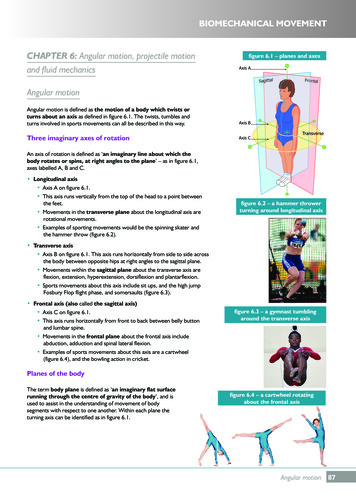
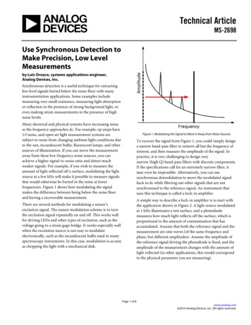
2. Basic concepts of spring-mass systemThe oscillatory motion is a motion of an object which returns to a given position after a fixed timeinterval. The basic concepts of SHM are well explained in most physics textbooks [4]. The main topicof this work, we presented the method to find the spring constant, using Hooke’s law and waveequation.2.1. Hooke’s lawFigure 1(a) shows the basic concept of spring-mass system given by Hooke’s law. The system consistsof a mass (𝑚) attached to one end of a spring which has spring constant (𝑘). The other end of thespring is mounted to a rigid support. The spring is stretched by a restoring force that is proportional tothe position (𝑥), therefore Hooke’s law can be applied in this situation [3]. The restoring force of theSHM can be written as𝐹𝑠 𝑘𝑥(1)The restoring force is a gravity force in this case, then𝑚𝑔 𝑘𝑥(2)2.2. Wave equationThe SHM is likely related to circular motion that can be explained by wave equation. From theequation 2, the accelerator of motion is written as the second derivative of the position with respect totime, according to𝑑2𝑥𝑘 𝑥2𝑑𝑡𝑚(3)In this case, we denote the constant of ratio 𝑘/𝑚 with the symbol 𝜔2 , then𝑑2𝑥 𝜔2 𝑥𝑑𝑡 2(4)The solution of displacement is a function of 𝑥(𝑡) that satisfies this second-order differentialequation, and is a mathematical representation of the position of an object as a function of time. Thefollowing cosine function solution can be written as𝑥(𝑡) 𝐴𝑐𝑜𝑠(𝜔𝑡 )(5)2𝜋 2)𝑇(6)𝑘 𝑚𝜔2 𝑚(The constant angle ( ) is called phase constant. (𝐴) represents an amplitude. The displacement as afunction of time graph for an object undergoing SHM is shown in figure 1(b). The experimentapparatus is designed to monitor under the both basic concepts. The spring constant will beinvestigated by curve fitting using Hooke’s law and the wave equation.
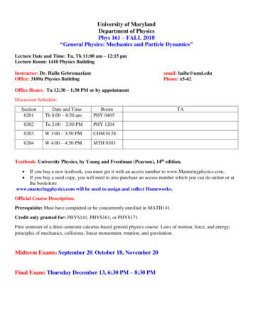
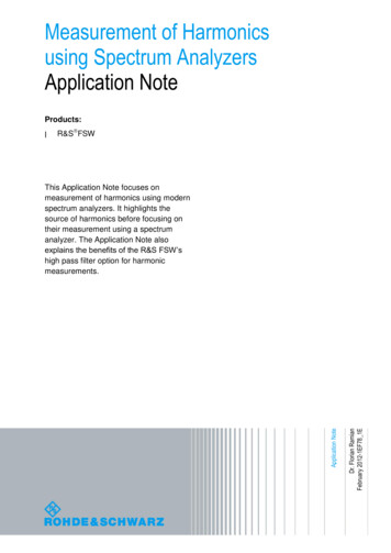
(a)(b)Figure 1. The basic concept of spring-mass system (a) Hooke’s law (b) The displacement as afunction of time graph for an object undergoing SHM (wave equation).3. Hardware and Software preparation3.1. HardwareThe experimental apparatus includes a microcontroller system (MCS), an ultrasonic sensor system(USS) and a spring-mass system (SMS). The MCS is a control system which consists of a 220 to 9VAC power supply, a 9 VAC to 9 VDC circuit, a 9V cooling fan and Arduino Uno R3. In figure 2, thefeatures are an 8-bit, 16 MHz board, a USB connection, a 9V power jack, 14 digital input/output pins(orange box) and 6 analogue input pins (green box). The Simple Harmonic Motion MCS box is shownin figure 2.USBFigure 2. The microcontroller system (MCS) unit.Figure 3. The ultrasonic system (USS) unit.
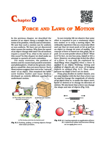
The USS, shown in figure 3, is a sensor system which consists of a HC-SR04 ultrasonic sensorcontaining 4 pins of 5VDC (working voltage, VCC pin, ground (GND pin), trig (Trig pin) and echo(Echo pin)). To generate eight pulses of a 40 kHz ultrasound, the trig pin is set for a high state of 10𝜇𝑠 and it will be received in the echo pin. After the echo signal is detected, the echo pin is reset to 0 V.The USS box is shown in figure 3. The SMS, shown in figure 4, consists of a spring, masses (madefrom 38.1 mm diameter cylindrical brass with two thicknesses of 0.2 and 0.4 mm related to theestimated weight of 0.017 and 0.034 kg, respectively) and a stand with clamp.Figure 4. The experimental apparatus set up including the SMS unit.3.2. SoftwareThe software has been developed using LabVIEW for user interface. To communicate the HC-SR04ultrasonic sensor with Arduino Uno R3, an easy to use add-on called LabVIEW VIs is provided byLINX for interfacing with the controller board with common embedded platforms like Arduino. Thebuilt in sensor VIs is used to access devices through the digital I/O, analog I/O, PWM, SPI, I2C,UART [5].Figure 5. The LabVIEW program is designed to measure the position of a mass attached on a springas a function of time.The SHM LabVIEW code is shown in figure 5. When the program is executed, the trig and echopin have to be set to the pin number of 11 and 12, respectively. The program will measure the distanceto the brass weight as a function of time after the run button is clicked. The stop button is clicked after10 seconds. Finally, the raw data of the distance to the brass weight is saved as a function of time.
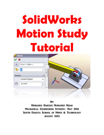
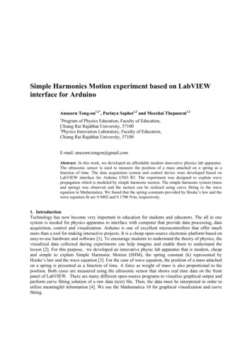
4. Experimental resultsThe raw data of the distance to the brass weight as a function of time is imported to Mathematica 10for data analysis. The Mathematica 10 is useful software for scientific calculation. The nonlinearmodel fit is used for curve fitting. A model is defined in the form of 𝐴 Cos[2 Pi (𝑡 tc) 𝑇] y0 .In this case, the equilibrium position of the brass weight (𝑦0 ) is 0.124540 0.000092 m, the initialphase amplitude (2 𝑃𝑖 𝑡𝑐) is 1.231550 0.011874 rad, the amplitude (𝐴) is0.016370 0.000130 m and the period (𝑇) is 0.700280 0.000216 s. The 𝑅 2 value is 0.97386,implying that the curve fitting, which is the sinusoidal model, can be used to describe the experimentaldata.(a)(b)Figure 6. The data curve fitting using Mathematica 10 and represented by Origin 8 (red dots are rawdata and black line is curve fitting) (a) wave equation (b) Hooke’s law.Figure 6(a) shows the value of the period received from the data curve fitting can be used tocalculate the spring constant using equation 6. The spring constant (𝒌) is 9.1706 N/m while the brassweight is 0.114 kg. To compare the spring constant with different experiments, the second experimentsetup similar to the same experiment can be used to investigate Hooke’s law. In this case, the brassweights used vary from 0.051 to 0.214 kg. The result shows that the displacement of spring (𝒙) is ananticipated linear behavior with the gravity force (𝒎𝒈) same as equation 2. The linear fitting, shownin figure 6(b), gives the slope value which is the spring constant (𝒌) of 9.9402 N/m.5. ConclusionsThe spring-mass system which is the Simple Harmonic Motion, based on LabVIEW interface forArduino has been developed to perform an innovative physics lab apparatus that are modern, cheapand simple. The HC-SR04 ultrasonic sensor is used to measure the position of a mass attached on aspring as a function of time. The experimental data and the theoretical model are in good agreement.The most important aspect is our students have used the STEM activity in order to integrate Science(physics concept), Technology (electronic circuit design and computer programming), Engineering(design and build apparatus) and Mathematics (investigate data using Mathematica).
References[1] Arduino.cc. (2017). Arduino - Home. [online] Available at: https://www.arduino.cc/ [Accessed19 April 2017].[2] Crockett, L. (2017). The Creative Classroom: Why We Must Teach With Imagination. [online]Global Digital Citizen Foundation. Available at: -teach-imagination [Accessed 10 Apr. 2017].[3] Serway, R. A. and Jewett, J. W. (2013). Physics for Scientists and Engineers with ModernPhysics. 9th ed. Brooks Cole, pp.450-456.[4] Pereira, N. (2016). Measuring the RC time constant with Arduino. Physics Education, f [Accessed 21 May 2017].[5] Labviewmakerhub.com. (2017). LINX [LabVIEW MakerHub]. [online] Available at:https://www.labviewmakerhub.com/doku.php?id libraries:linx:start [Accessed 19 Apr.2017].AcknowledgementWe would like to thanks Mr.Chatchaboom Thammathong for valuable suggestions and very helpful,our students (Mrs.Kannika Supasorn and Mrs.Suthigarn Vichar) are work really hard and payattention. This work has been supported by Faculty of Education and the funding agencies of Researchand Development Institute, Chiang Rai Rajabhat University.
LINX for interfacing with the controller board with common embedded platforms like Arduino. The built in sensor VIs is used to access devices through the digital I/O, analog I/O, PWM, SPI, I2C, UART [5]. Figure 5. The LabVIEW program is designed to measure the position of a mass attached on a spring as a function of time.