Transcription
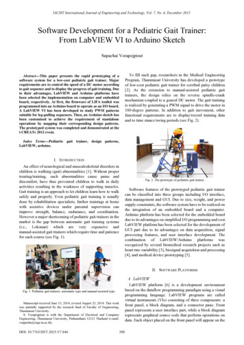
IACSIT International Journal of Engineering and Technology, Vol. 7, No. 6, December 2015Software Development for a Pediatric Gait Trainer:From LabVIEW VI to Arduino SketchSupachai VorapojpisutTo fill such gap, researchers in the Medical EngineeringProgram, Thammasat University has developed a prototypeof low-cost pediatric gait trainer for cerebral palsy children[2]. As the extension to manual-assisted pediatric gaittrainers, the design relies on the reverse spindle-crankmechanism coupled to a geared DC motor. The gait trainingis realized by generating a PWM signal to drive the motor in180-degree patterns. In addition to gait movement, otherfunctional requirements are to display/record training dataand to time stance/swing periods (see Fig. 2).Abstract—This paper presents the rapid prototyping of asoftware system for a low-cost pediatric gait trainer. Majorrequirements are to control the speed of a DC motor accordingto gait sequence and to display the progress of gait training. Dueto their advantages, LabVIEW and Arduino platforms havebeen selected the implementation on computer and embeddedboard, respectively. At first, the firmware of LIFA toolkit wasprogrammed into an Arduino board to operate as an I/O board.A LabVIEW VI has been developed to study PWM patternssuitable for leg-pulling sequences. Then, an Arduino sketch hasbeen customized to achieve the requirement of standaloneoperations by mapping their corresponding design patterns.The prototyped system was completed and demonstrated at thei-CREATe 2012 event.Index Terms—Pediatric gait trainer, design patterns,LabVIEW, arduino.I. INTRODUCTIONAn effect of neurological and musculoskeletal disorders inchildren is walking (gait) abnormalities [1]. Without propertreating/training, such abnormalities cause pains anddiscomfort, have thus prevented children to walk in dailyactivities resulting in the weakness of supporting muscles.Gait training is an approach to let children learn how to walksafely and properly. Even pediatric gait training is usuallydone by rehabilitation specialists; further trainings at homewith assistive devices under parental supervision canimprove strength, balance, endurance, and coordination.However a major shortcoming of pediatric gait trainers in themarket is the gap between automatic gait training systems(i.e., Lokomat) which are very expensive andmanual-assisted gait trainers which require time and patiencefor each course (see Fig. 1).Fig. 2. The prototype of pediatric gait trainer.Software features of the prototyped pediatric gait trainercan be classified into three groups including I/O interface,data management and GUI. Due to size, weight, and powersupply constraints, the software system have to be realized onthe integration of an embedded board and a computer.Arduino platform has been selected for the embedded boarddue to its advantages on simplified I/O programming and cost.LabVIEW platform has been selected for the development ofGUI part due to its advantages on data acquisition, signalprocessing features, and user interface development. Thecombination of LabVIEW/Arduino platforms wasrecognized by several biomedical research projects such asheart rate variability [3], biosignal acquisition and processing[4], and medical device prototyping [5].II. SOFTWARE PLATFORMSA LabVIEWLabVIEW platform [6] is a development environmentbased on the dataflow programming paradigm using a visualprogramming language. LabVIEW programs are calledvirtual instruments (VIs) consisting of three components: afront panel, a block diagram, and a connector pane. Frontpanel represents a user interface part, while a block diagramrepresents graphical source code that perform operations ondata. Each object placed on the front panel will appear on theFig. 1. Pediatric gait trainers: automatic type and manual-assisted type.Manuscript received June 15, 2014; revised August 25, 2014. This workwas partially supported by the research fund of Faculty of Engineering,Thammasat University.S. Vorapojpisut is with the Department of Electrical and ComputerEngineering, Thammasat University, Pathumthani 12121 Thailand (e-mail:vsupacha@engr.tu.ac.th).DOI: 10.7763/IJET.2015.V7.846508
IACSIT International Journal of Engineering and Technology, Vol. 7, No. 6, December 2015transferred to an Arduino board via its USB interface. Themain advantage of the Arduino software platform is its“Wiring” library that abstracts the hardware access.Therefore I/O programming can be done without theknowledge of microcontroller.Arduino platform has been extended in many formsregarding to its open-source license. The existence of manyclone boards makes the price to be as low as 9. While theporting of Arduino APIs to other microcontrollers makes thecode to be portable across different processor architecture.Such flexibility gives a benefit for using Arduino boards incost-constrained applications.back panel as terminals. The graphical approach allowsdevelopers to build VIs by dragging and dropping nodesrepresenting inputs, outputs, structures, and functions intoworking area. Then nodes are connected using wires totransfer data (see Fig. 3).C LabVIEW Interface For Arduino ToolkitLabVIEW Interface For Arduino toolkit or LIFA [8] is aLabVIEW library to interface with Arduino boards. Using asketch provided with the LIFA toolkit, an Arduino board canbe used as a data acquisition (DAQ) hardware. Digital I/Osand voltage measurement with analog pins can be managedfrom within LabVIEW VI without any C/C code.However the pre-programmed Arduino board must beconnected to the computer with LabVIEW through a USBlink (see Fig. 5).Fig. 3. LabVIEW front panel and block diagram.LabVIEW development addresses measurement and dataanalysis requirements with the concept of Acquire-Analyze-Present. The acquisition part is to collect data fromhardware and user interface. The analysis part is to performmathematical and logical operations on the collected data.Then the presentation part is to display the analyzed data inmeaningful ways.Fig. 5. Nodes available in the LIFA toolkit.III. DESIGN PATTERNSB ArduinoArduino [7] is an open-source electronics prototypingplatform designed to provide inexpensive devices thatinteract with their environment using sensors and actuators.Arduino hardware is a single-board computer based on an8-bit Atmel AVR, or a 32-bit Atmel ARM microcontroller.The standardized I/O interface consists of 6 analog input pins,and 14 digital pins which also support serial and PWMfeatures as illustrated in Fig. 4.Design patterns are general reusable solutions tocommonly occurring problems within a given context insoftware design. As description or template, applying designpatterns in software development provides simplicity andalso reliability.Fig. 6. Design pattern: state machine.A LabVIEW Design PatternsSince LabVIEW uses a graphical dataflow programmingapproach, design patterns are templates of interconnectionamong structures(while/case/for) and nodes as pre-existingsolutions to common problems. There are five designpatterns [9] suggested by National Instruments:Fig. 4. Arduino Uno board with pin arrangement.Using an integrated development environment (IDE) oncomputers, Arduino programs are written using C or C .The code or sketch is built using cross toolchain and509
IACSIT International Journal of Engineering and Technology, Vol. 7, No. 6, December 2015y Functional global variable,y State machine,y Event-driven user interface,y Producer/consumer,y Queued state machine.Two design patterns considered in our development arestate machine for PWM generation and event-driven userinterface for interactive parameter management.The state machine pattern uses a case structure within awhile loop as shown in Fig. 6. Each case represents thesystem state with shift registers to pass the value of nextstates.Fig.7 shows the event-driven user interface pattern basedon a nested event structure within a while loop. The eventstructure will be blocked until receiving registered events ortimeout.The state pattern in Fig. 8 is analogous to the state machinepattern in Fig. 6. Therefore the code porting of a switchstructure in a VI into a family of handler functions can beperformed by mapping events and states into switchstatements in C code.IV. SOFTWARE DEVELOPMENT OF GAIT TRAINERThe main concept is to partition software developmentprocess into three phases (Development-ImplementationDeployment) according to corresponding users. To shortendelivery time, the development process follows theevolutionary prototyping approach in which softwareartifacts of each phase are reused as the starting point of nextphase.A Software RequirementsSoftware requirements are formulated based on the mainuser of software system in each phase. In the Developmentphase, the main user is the research team who is responsiblefor the investigation of suitable profile parameters. Thereforethe main requirement is to develop an interactive UI part foradjusting and generating PWM patterns.In the Implementation phase, the main user becomes aselected group of rehabilitation specialists who will feedbacktheir experience and suggestion on the prototype gait trainer.The main requirement of this phase is to make the prototypeembedded board running stand-alone, while PC software isused for monitoring purpose via wireless communication.Finally the main user of the Deployment phase will bestaffed at the rehabilitation center and children families. Tworequired features for each user group are data collection frommultiple gait trainers and on-board UI respectively.Fig. 7. Design pattern: event-driven user interface.B Arduino Design PatternsDesign patterns for Arduino are similar to those [10]available to C/C development. Internally, the adapterpattern has been applied extensively to realize the hardwareabstraction of I/O interfaces. Therefore Arduino API isalmost unified across hardware platforms. The state pattern iswidely used in applications that implement a commandhandler for serial protocol. For a simple command handler,the C-based pseudo-code as listed in Fig. 8 shows thestructure of a hierarchical switch statement that processesreceived commands.B Software DesignBy assisting each walk with two strings attached with eachknee, the major concern of firmware development is thesafety of children from improper string pulling force that isgenerated by constant and fixed PWM signals. To overcomethis concern, we have proposed the generation of motordriving signals based on a four-modes PWM profile asdepicted in Fig. 9.int state FIRST STATE;void commandHandler() {while ( Serial.available() && c ! '\n' ) {c Serial.read();cmdbuf[i ] c;}if ( c '\n' ) {event parseCommand(cmdbuf);switch (state) {case FIRST STATE:state firstStateHandler(event);break;.}}}int firstStateHandler(int event) {int nextState STATE0;switch (event) {case EVENT0:transitionCode();nextState SECOND STATE;break;.}return nextState;}Fig. 8. State machine implementation for command handler.positiondetectedCONTINUEHOLDsensor notdetectedbutton pressPULLT PULL periodT FOLLOW periodFOLLOWFig. 9. State machine of the proposed PWM profile.PULL mode: duty cycle is increased to the maximum value(PULL PWM) within a given period (PULL period). Theobjective of this mode is to apply enough pulling force toraise the child’s foot off the ground, hence assists thepropulsion in stance phase.FOLLOW mode: duty cycle is decreased from themaximum value to a value (FOLLOW PWM) within aspecified period (FOLLOW period). This mode matches the510
IACSIT International Journal of Engineering and Technology, Vol. 7, No. 6, December 2015toe-off in swing phase in which leg motion is less resistanceto pull strings.CONTINUE mode: duty cycle is maintained at a value(CONTINUE PWM) until marked crank position is detected,i.e. the presence of heel strike in the swing phase. Since bothstrings are slack, the objective of this mode is to complete theswing phase as fast as possible.HOLD mode: duty cycle is maintained at the lowest level(HOLD PWM) enough to hold the tension within the string.Therefore, self-walk situations can be detected by checkingthe status of crank position sensor. To assist a walk, a buttonis pressed to advance into the PULL mode.Due to the difference in weight and height of child patients,six parameters can be customized for each patient, namelyPULL PWM, PULL period, FOLLOW PWM, FOLLOWperiod, CONTINUE PWM, and HOLD PWM.loop has been ported into a customized Arduino firmwaresuch that the prototype gait trainer can be used independentlyof the PC. Two matched XBee modules were selected torealize wireless communication between the PC and theArduino board. Since the control loop in the original VI isimplemented based on the state machine pattern, the codeporting has been performed by mapping the logic depicted inFig. 9 into corresponding event and state enumerations.V. RAPID PROTOTYPING OF SOFTWARE SYSTEMAt first, the software system was developed using theLIFA toolkit consisting of a LabVIEW library and a sourcecode of Arduino firmware. The usage of LIFA toolkit relieson the LabVIEW programming model to communicate aseries of commands synchronously with the Arduinofirmware. In other words, Arduino board is just an I/O boarddirectly managed by VIs.Based on the requirement of the Development phase, wehave developed a VI consisting of a UI and a control loops togenerate PWM signal via an Arduino Mega 2560 boardinteractively. Since no work is needed on the Arduino side,the first revision of working software was finished within oneweek with some limitations: on-screen button and wiredcommunication via USB cable as shown in Fig. 10. Fig. 11shows the overview of two loops that handles UI and controlsthe speed of DC motor, respectively. Then the workingsoftware has been experimented with some children at arehabilitation center to find an appropriate set of parameters.Fig. 12. New monitoring loop of the Implementation phase.Based on the original LIFA firmware, three additionalcommands (read profile, update profile, and read status) havebeen implemented to support the UI-based parameterconfiguration, while the VI control loop was replaced by amonitoring loop as illustrated by Fig. 12.Following the concept of evolutionary prototyping, almostof a UI portion of the PC is not modified except for thereplacement of “STEP” button with the “UPDATE” button.The software transition was also finished within one weekwith respect to the reuse of UI portion and the command loopin LIFA firmware. At present, we are working on theextension of the VI to support the management of multiplegait trainers.VI. CONCLUSIONThis paper concludes our experience on the developmentof LabVIEW VIs and an Arduino sketch for a prototypedpediatric gait trainer. The main objective is to develop asoftware system to control the operation of the gait trainerbased on two major requirements; multi-mode speed controland UI for clinical tests. Based on the state machine pattern,LabVIEW VIs has been developed to realize UI and controlfeatures. Then the control loop portion has been ported to acustomized Arduino sketch via the mapping into the statepattern. By matching design patterns, the development ofboth LabVIEW VIs and Arduino sketch was rapidlyprototyped within a very short period.Fig. 10. User interface in the Development phase.REFERENCES[1]Fig. 11. Two major loops of the VI: UI handler and control loop.[2]In the second phase, the operation of LabVIEW control511C. Nieuwenhuijsen, M. Donkervoort, W. Nieuwstraten et al,“Experienced problems of young adults with cerebral palsy: Targets forrehabilitation care,” Archives of Physical Medicine and Rehabilitation,vol. 90, pp. 1891-1897, 2009.M. Jirojananukun and B. Rungroungdouyboon, “Design assistivestepping for posterior walker in cerebral palsy children,” presented at
IACSIT International Journal of Engineering and Technology, Vol. 7, No. 6, December 2015[3][4][5][6][7][8]the 22nd Conf. of The Mechanical Engineering Network in Thailand,ChiangMai, Thailand, 2012.M. Schiavenato, C. Oliu, E. Bello, J. Bohorquez, and N. Claure,“Development of a system for the assessment of heart rate variability inthe NICU,” in Proc. the 29th Biomedical Engineering Conference,Miami, 2013, pp. 25-26.H. P. da Silva, A. Lourenço, A, Fred, and R. Martins, “BIT: Biosignaligniter toolkit,” Computer Methods and Programs in Biomedicine, vol.115, pp. 20-32, June 2014.C. Loncaric, Y. Tang, C. Ho, M. A. Parameswaran, and H. Yu, “AUSB-based electrochemical biosensor prototype for point-of-carediagnosis,” Sensors and Actuators B: Chemical, vol. 161, pp. 908-913,Jan. 2012.J. Travis and J. Kring, LabVIEW for Everyone: GraphicalProgramming Made Easy and Fun, Prentice Hall, 2006.M. Banzi, Getting Started with Arduino, 2nd ed., Maker Media, 2011.A. Jamaluddin, L. Sihombing, A. Supriyanto, A. Purwanto, and M.Nizam, “Design real time battery monitoring system using labviewinterface for arduino (LIFA),” in Proc. the Joint Int.Conf. on RuralInformation & Communication Technology and Electric-VehicleTechnology, Bandung, Indonesia, 2013, pp. 1-4.[9] National Instruments. (2012). Design Patterns in LabVIEW. [Online].Available: http://www.ni.com/white-paper/7605/en/.[10] B .P. Douglass, Design Patterns for Embedded Systems in C: AnEmbedded Software Engineering Toolkit, Newnes, 2010.Supachai Vorapojpisut was graduated from TokyoInstitute of Technology, Japan with the degree of D.Eng(control engineering) in 2000. He works as an assistantprofessor at the Department of Electrical and ComputerEngineering, Thammasat University, Thailand.His research interests include wireless sensornetworks, embedded software development, andcomputer applications in measurement and control.512
LabVIEW Interface For Arduino toolkit or LIFA [8] is a LabVIEW library to interface with Arduino boards. Using a sketch provided with the LIFA toolkit, an Arduino board can be used as a data acquisition (DAQ) hardware. Digital I/Os and voltage measurement with analog pins can be managed from within LabVIEW VI without any C/C code. However the .