Transcription
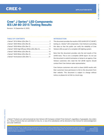
AS524714-Bit Dual-Die On-Axis MagneticRotary Position Sensor with 11-BitBinary Incremental Pulse CountGeneral DescriptionThe AS5247 is a high-resolution redundant rotary positionsensor for fast absolute angle measurement over a full360-degree range. This new position sensor is equipped with arevolutionary integrated dynamic angle error compensation(DAEC ) with almost 0 latency.The robust design of the device suppresses the influence of anyhomogenous external stray magnetic field. A standard 4-wireSPI serial interface allows a host microcontroller to read 14-bitabsolute angle position data from the AS5247 and to programnon-volatile settings without a dedicated programmer.Incremental movements are indicated on a set of ABI signalswith a maximum resolution of 2048 steps / 512 pulses perrevolution. The resolution of the ABI signal is programmable to1024 steps / 256 pulses per revolution.Brushless DC (BLDC) motors are controlled through a standardUVW commutation interface with a programmable number ofpole pairs from 1 to 7. The absolute angle position is alsoprovided as PWM-encoded output signal.The AS5247 supports embedded self-diagnostics includingmagnetic field strength too high, magnetic field strength toolow or lost magnet, and other related diagnostic features.The AS5247 is available as a dual die in a compact MLF-40 7x7package.Ordering Information and Content Guide appear at end ofdatasheet.Key Benefits & FeaturesThe benefits and features of AS5247, 14-bit Dual-Die On-AxisMagnetic Rotary Position Sensor with 11-bit Binary IncrementalPulse Count are listed below:Figure 1:Added Value of Using the AS5247BenefitsFeatures Easy to use – saving costs on DSP DAEC Dynamic angle error compensation Good resolution for motor and position control 14-bit core resolution Versatile choice of the interface Independent output interfaces: SPI, ABI, UVW,PWMams Datasheet[v1-10] 2016-Dec-05Page 1Document Feedback
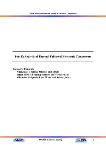
AS5247 General DescriptionBenefitsFeatures No programmer needed (via SPI command) Zero position, configuration programmable Supports safety-critical applications Self-Diagnostics and redundancy Lower system costs (no shielding) Immune to external stray fieldApplicationsThe AS5247 has been designed to support BLDC motorcommutation for the most challenging and safety-criticalautomotive applications (AEC-Q100 grade 0 automotivequalified) such as electric power steering (EPS), transmission(gearbox, actuator), brake (actuator) and starter & alternator.Block DiagramThe functional blocks of this device are shown below:Figure 2:AS5247 Block DiagramVDD3V3 TVDD3V3 BCSn TCLK TMISO TVolatile MemoryAS5247SPIOTPMOSI TCSn BCLK BLDOVDD TMISO BVDD BMOSI POLATORA BB BI B/PWM BDynamic AngleErrorCompensationUWVU TV TW T / PWM TPWM DecoderSelectableOn I or WU BV BW B / PWM BAGCGND BPage 2Document FeedbackA TB TI T/PWM TGND Tams Datasheet[v1-10] 2016-Dec-05
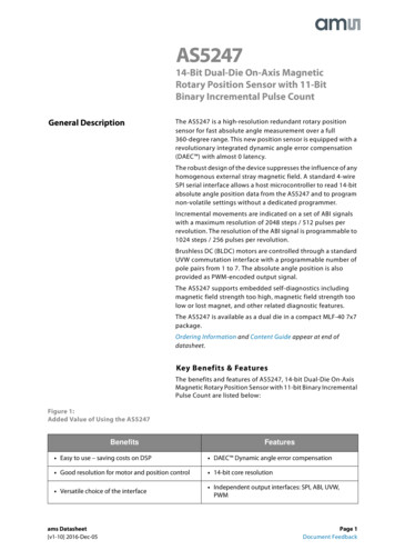
AS5247 Pin AssignmentPin AssignmentCSn T1CLK B2CLK T3313233343536373840The suffix on the signal name indicateswhich of the two internal chips isconnected to the pin(T top die, B bottom die). Thepackage contains two identical chips,and no pins are shared by both chips.39Figure 3:MLF 40 Pin AssignmentAS5235AS524730GND T29GND B28VDD3V3 T27VDD3V3 B26VDD T25VDD BMISO B4MISO T5MOSI B6MOSI T724U TTest B823U B22V T21V B141516171819ncncncncncW B/PWM B2013A TW T/PWM T121011B BB T9A BTest TEPFigure 4:Pin DescriptionPin NumberPin NamePin Type1CSn TDigital InputSPI chip select (active low)2CLK BDigital InputSPI Clock3CLK TDigital InputSPI Clock4MISO BDigital OutputSPI master data input, slave output5MISO TDigital OutputSPI master data input, slave output6MOSI BDigital InputSPI master data output, slave input7MOSI TDigital InputSPI master data output, slave input8Test BTest pin. Connected to ground9Test TTest pin. Connected to ground10B BDigital OutputIncremental signal B11B TDigital OutputIncremental signal B12A BDigital OutputIncremental Signal Aams Datasheet[v1-10] 2016-Dec-05Pin DescriptionPage 3Document Feedback
AS5247 Pin AssignmentPin NumberPin NamePin Type13A TDigital Output14ncNot connected15ncNot connected16ncNot connected17ncNot connected18ncNot connected19W B/PWM BDigital OutputCommutation signal W or PWM encoded output20W T/PWM TDigital OutputCommutation signal W or PWM encoded output21V BDigital OutputCommutation signal V22V TDigital OutputCommutation signal V23U BDigital OutputCommutation signal U24U TDigital OutputCommutation signal U25VDD BPower Supply5V power supply voltage for on-chip regulator26VDD TPower Supply5V power supply voltage for on-chip regulator27VDD3V3 BPower Supply3.3V on-chip low-dropout (LDO) output.Requires an external decoupling capacitor (1uF)28VDD3V3 TPower Supply3.3V on-chip low-dropout (LDO) output.Requires an external decoupling capacitor (1uF)29GND BPower SupplyGround30GND TPower SupplyGround31I B/PWM BDigital OutputIndex signal or PWM encoded output32I T/PWM TDigital OutputIndex signal or PWM encoded output33n.c34n.cPage 4Document FeedbackPin DescriptionIncremental Signal Aams Datasheet[v1-10] 2016-Dec-05
AS5247 Pin AssignmentPin NumberPin Name35n.c36n.c37n.c38n.c39n.c40CSn BPin TypePin DescriptionSPI chip select (active low)Note(s) and/or Footnote(s):1. Floating state of a digital input is not allowed.2. If SPI is not used, a Pull up resistor on CSn is required.3. If SPI is not used, a Pull down resistor on CLK and MOSI is required.4. If SPI is not used, the pin MISO can be left open.5. If ABI, UVW or PWM is not used, the pins can be left open.ams Datasheet[v1-10] 2016-Dec-05Page 5Document Feedback
AS5247 Absolute Maximum RatingsAbsolute Maximum RatingsStresses beyond those listed under Absolute Maximum Ratingsmay cause permanent damage to the device. These are stressratings only. Exposure to absolute maximum rating conditionsfor extended periods may affect device reliability. Parametersregarding normal operation of the sensor are listed in sectionElectrical Characteristics.Figure 5:Absolute Maximum RatingsParameterSymbolMinMaxUnitsDC supply voltage at VDD pinVDD5-0.37.0VDC supply voltage at VDD3V3 pinVDD3-0.35.0VDC supply voltage at GND pinVSS-0.30.3VInput pin voltageVinVDD 0.3VInput current (latch-up immunity)Iscr100mANorm:AEC-Q100-004Electrostatic dischargeESDkVNorm:AEC-Q100-002Total power dissipation (all suppliesand outputs)-100 2Pt150mWNoteAmbient temperature 5V0Ta5V0-40150 CIn the 5.0V powersupply mode onlyAmbient temperature 3V3Ta3V3-40150 CIn the 3.3V powersupply mode ifNOISESET 1Programming temperatureTaProg545 CProgramming @room temperature(25 C 20 C)Storage temperatureT strg-55150 CPackage body temperatureT body260 C85%Relative humidity non-condensingRHNCMoisture sensitivity levelMSLPage 6Document Feedback53Norm: IPC/JEDECJ-STD-020Represents amaximum floorlifetime of 168hams Datasheet[v1-10] 2016-Dec-05
AS5247 Electrical CharacteristicsElectrical CharacteristicsAll limits are guaranteed. The parameters with min and maxvalues are guaranteed with production tests or SQC (StatisticalQuality Control) methods.Figure 6:Electrical nitVDDPositive supplyvoltage5.0V operation mode4.55.05.5VVDD3V3Positive supplyvoltage3.3V operation mode;only from -40 C to 125 C3.03.33.6VVDD3V3 150Positive supplyvoltage3.3V operation mode;only from -40 C to 150 C(Noiseset Bit has to be set)3.03.33.6VVDD BurnPositive supplyvoltageSupply voltage requiredfor programming in 3.3Voperation3.33.5VRegulated VoltageVoltage at VDD3V3 pin ifVDD VDD3V33.23.6VIDDSupply currentOnly for one die. Must bemultiplied by 215mAVIHHigh-level inputvoltageVILLow-level inputvoltageVREG3.40.7 VDDV0.3 VDDVVSS 0.4VVOHHigh-level outputvoltageVOLLow-level outputvoltageI OutCurrent on digitaloutput A, B, I, U, V, W1mAI Out MISOCurrent on digitaloutput MISO4mAC LCapacitive load ondigital output50pFams Datasheet[v1-10] 2016-Dec-05VDD - 0.5Page 7Document Feedback
AS5247 Magnetic CharacteristicsMagnetic CharacteristicsFigure 7:Magnetic SpecificationsSymbolBzParameterOrthogonal magneticfield strength, normaloperating modeConditionsMinRequired orthogonal component ofthe magnetic field strength measuredat the die's surface along a circle of1.1mm35TypMaxUnit70mTNote(s) and/or Footnote(s):1. It is possible to operate the AS5247 below 35mT with reduced noise performance.System CharacteristicsFigure 8:System SpecificationsSymbolRESRES ABIINLOPT @ 25 CParameterConditionsMinCore resolutionResolution of theABI interfaceTypMax14Programmable withregister setting(ABIRES)Non-linearity,optimum placementof the magnet10Unitsbit11bit 0.9degreeNon-linearity @displacement ofmagnet andtemperature -40 Cto 150 CAssuming N35HMagnet(D 8mm, H 3mm)500um displacementin x and yz-distance @ 2000um 1.4degreeONLRMS output noise(1 sigma)Orthogonalcomponent for themagnetic field withinthe specified range(Bz), NOISESET 00.068degreeONHRMS output noise(1 sigma) on SPI, ABIand UVW interfacesOrthogonalcomponent for themagnetic field withinthe specified range(Bz), NOISESET 10.082degreeINLDIS TEMPPage 8Document Feedbackams Datasheet[v1-10] 2016-Dec-05
AS5247 Timing nits0.068degreeRMS output noise(1 sigma) on PWMinterfaceOrthogonalcomponent for themagnetic field withinthe specified range(Bz)tdelaySystem propagationdelay –coreReading angle via SPI90110μstdelaySystem propagationdelay after dynamicangle errorcorrection.At ABI and UVWinterfaces1.51.9μsSampling rateRefresh rate at SPI202247nsDAE1700Dynamic angle errorAt 1700 RPM constantspeed0.02degreeDAEmaxDynamic angle errorAt 14500 RPMconstant speed0.18degreeDAEaccDynamic angle errorat constantacceleration(25krad/s²)25k radians/s²constant acceleration0.175degree14500RPMON PWMDAECtsamplMS222Maximum speedReference magnet: N35H, 8mm diameter; 3mm thicknessTiming CharacteristicsFigure 9:Timing n timeNot tested, guaranteed bydesign. Time betweenVDD VDDmin and thefirst valid outcomeams Datasheet[v1-10] 2016-Dec-05MinTypMaxUnits10msPage 9Document Feedback
AS5247 Detailed DescriptionDetailed DescriptionThe AS5247 is a Hall-effect magnetic sensor using a CMOSlateral technology. The lateral Hall sensors convert themagnetic field component perpendicular to the surface of thechip into a voltage.The signals from the Hall sensors are amplified and filtered bythe analog front-end (AFE) before being converted by theanalog-to-digital converter (ADC). The output of the ADC isprocessed by the hardwired CORDIC (coordinate rotatingdigital computer) block to compute the angle and magnitudeof the magnetic vector. The intensity of the magnetic field(magnitude) is used by the automatic gain control (AGC) toadjust the amplification level for compensation of thetemperature and magnetic field variations.The internal 14-bit resolution is available by readout registervia the SPI interface. The resolution on the ABI output can beprogrammed for 10 or 11bits.The Dynamic Angle Error Compensation block corrects thecalculated angle regarding latency, by using a linear predictioncalculation algorithm. At constant rotation speed the latencytime is internally compensated by the AS5247, reducing thedynamic angle error at the SPI, ABI and UVW outputs. TheAS5247 allows selecting between a UVW / ABI output and aPWM-encoded interface on the W-pin or the I-pin.At higher speeds, the interpolator fills in missing ABI pulses andgenerates the UVW signals with no loss of resolution. Thenon-volatile settings in the AS5247 can be programmedthrough the SPI interface without any dedicated programmer.Power ManagementThe AS5247 can be either powered from a 5.0V supply using theon-chip low-dropout regulator or from a 3.3V voltage supply.The LDO regulator is not intended to power any other loads,and it needs a 1 μF capacitor to ground located close to the chipfor decoupling as shown in Figure 11.In 3.3V operation, VDD and VDD3V3 must be tied together. Inthis configuration, normal noise performance (ONL) is availableat reduced maximum temperature (125 C) by clearingNOISESET to 0 (default configuration). When NOISESET is set to1, the full temperature range is available with reduced noiseperformance (ONH).Figure 10:Temperature Range and Output Noise in 3.3V and 5.0V ModeVDD (V)NOISESETTemperature Range ( C)RMS Output Noise (degree)5.00-40 1500.0683.30-40 1250.0683.31-40 1500.082Page 10Document Feedbackams Datasheet[v1-10] 2016-Dec-05
AS5247 Detailed DescriptionFigure 11:5.0V and 3.3V Power Supply Options5.0V Operation4.5 - 5.5VVDDLDO100nF3.3V OperationVDD3V33.0 – 3.6V1µF100nFGNDVDDVDD3V3LDOGNDAS5247AS5247After applying power to the chip, the power-on time (tpon)must elapse before the AS5247 provides the first valid data.Dynamic Angle Error CompensationThe AS5247 uses 4 integrated Hall sensors on Bottom Die andTop Die, which produce a voltage proportional to theorthogonal component of the magnetic field to the die. Thesevoltage signals are amplified, filtered, and converted into thedigital domain to allow the CORDIC digital block to calculatethe angle of the magnetic vector. The propagation of thesesignals through the analog front-end and digital back-endgenerates a fixed delay between the time of measurement andthe availability of the measured angle at the outputs. Thislatency generates a dynamic angle error, represented by theproduct of the angular speed ω and the system propagationdelay (tdelay):(EQ1)DAE ω x tdelayThe dynamic angle compensation block calculates the currentmagnet rotation speed (ω) and multiplies it with the systempropagation delay (tdelay) to determine the correction angleto reduce this error. At constant speed, the residual systempropagation delay is tdelay DAEC.The angle represented on the PWM interface is notcompensated by the Dynamic Angle Error Compensationalgorithm. It is also possible to disable the Dynamic Angle ErrorCompensation with the DAECDIS setting. Disabling theDynamic Angle Error Compensation gives a noise benefit of0.016 degree rms. This setting can be advantageous for lowspeed ( under 100 RPM) respectively static positioningapplications.ams Datasheet[v1-10] 2016-Dec-05Page 11Document Feedback
AS5247 Detailed DescriptionSPI Interface (slave)The SPI interface is used by a host microcontroller (master) toread or write the volatile memory, as well as to program thenon-volatile OTP registers. The AS5247 SPI only supports slaveoperation mode. It communicates at clock rates up to 10 MHz.The AS5247 SPI uses mode 1 (CPOL 0, CPHA 1) to exchangedata. As shown in Figure 12, a data transfer starts with thefalling edge of CSn (CLK is low). The AS5247 samples MOSI dataon the falling edge of CLK. SPI commands are executed at theend of the frame (rising edge of CSn). The bit order is MSB first.Data is protected by parity.SPI TimingThe AS5247 SPI timing is shown in Figure 12.Figure 12:SPI Timing MOSI(Input)Page 12Document Feedbackdata[15]data[14]data[0]ams Datasheet[v1-10] 2016-Dec-05
AS5247 Detailed DescriptionFigure 13:SPI TimingParameterDescriptionMintLTime between CSn falling edge and CLK rising edge350nstclkSerial clock period100nstclkLLow period of serial clock50nstclkHHigh period of serial clock50nstclk/2nsTime between last falling edge of CLK and risingedge of CSntHMaxUnitstCSnHigh time of CSn between two transmissions350nstMOSIData input valid to falling clock edge20nstMISOCLK edge to data output valid51nsRelease bus time after CS rising edge.10nstOZSPI TransactionAn SPI transaction consists of a 16-bit command frame followedby a 16-bit data frame. Figure 14 shows the structure of thecommand frame.Figure 14:SPI Command FrameBitNameDescription15PARCParity bit (even) calculated on the lower 15 bits ofcommand frame14R/W0: Write1: Read13:0ADDRAddress to read or writeTo increase the reliability of communication over the SPI, aneven parity bit (PARC) must be generated and sent. A wrongsetting of the parity bit causes an parity bit error which is shownthe PARERR bit in the error flag register. The parity bit iscalculated from the lower 15 bits of the command frame. The16-bit command consists of a register address and read/writebit which indicates if the transaction is a read or write and theparity bit. Figure 15 shows the read data frame.ams Datasheet[v1-10] 2016-Dec-05Page 13Document Feedback
AS5247 Detailed DescriptionFigure 15:SPI Read Data FrameBitNameDescription15PARDParity bit (even) calculated on the lower 15 bits of the readdata frame14EF13:0DATA0: No command frame error command occurred1: Error occurredDataThe data is sent on the MISO pin. The parity bit PARD iscalculated by the AS5247 of the lower 15 bits of data frame. Ifan error is detected in the previous SPI command frame, the EFbit is set high. The SPI read is sampled on the rising edge of CSnand the data is transmitted on MISO with the next readcommand, as shown in Figure 16.Figure 16:SPI ReadCSnMOSIMISOPage 14Document FeedbackCommandCommandCommandCommandRead ADD[m]Read ADD[n]Read ADD[o]Read ADD[p]DataDataDataDATA (ADD[m])DATA (ADD[n])DATA (ADD[o])ams Datasheet[v1-10] 2016-Dec-05
AS5247 Detailed DescriptionFigure 17:SPI Write Data FrameBitName15PARC14013:0DATADescriptionParity bit (even)Always lowDataThe parity bit PARC is calculated from the lower 15 bits of dataframe.In a SPI write transaction, the write command frame is followedby a write data frame at MOSI. The write data frame consists ofthe new content of register which address is defined in thecommand frame.During the new content is transmitted on MOSI by the writedata frame, the old content is send on MISO. At the nextcommand on MOSI the actual content of the register istransmitted on MISO, as shown in Figure 18.Figure 18:SPI Write TransactionCSnCommandMOSIWrite ADD[n]Data to write into ADD[n]DATA (x)Data content ADD[n]MISOams Datasheet[v1-10] 2016-Dec-05DATA (ADD[n])CommandWrite ADD[m]New Data contentof ADD[n]DATA (x)Data to write into ADD[m]DATA (y)Data content ADD[m]DATA (ADD[m])CommandNextcommandNew Data contentof ADD[m]DATA (y)Page 15Document Feedback
AS5247 Detailed DescriptionVolatile RegistersThe volatile registers are shown in Figure 19. Each register hasa 14-bit address.Figure 19:Volatile Register o operation0x0001ERRFL0x0000Error register0x0003PROG0x0000Programming register0x3FFCDIAAGC0x0180Diagnostic and AGC0x3FFDMAG0x0000CORDIC magnitude0x3FFEANGLEUNC0x0000Measured angle without dynamic angleerror compensation0x3FFFANGLECOM0x0000Measured angle with dynamic angle errorcompensationReading the NOP register is equivalent to a nop (no operation)instruction for the AS5247.Figure 20:ERRFL (0x0001)NameRead/WriteBit PositionDescriptionPARERRR2Parity errorINVCOMMR1Invalid command error: set to 1 by reading orwriting an invalid register addressFRERRR0Framing error: is set to 1 when anon-compliant SPI frame is detectedReading the ERRFL register automatically clears its contents(ERRFL 0x0000).Page 16Document Feedbackams Datasheet[v1-10] 2016-Dec-05
AS5247 Detailed DescriptionFigure 21:PROG (0x0003)NameRead/WriteBit PositionDescriptionPROGVERR/W6Program verify: must be set to 1 forverifying the correctness of the OTPprogrammingPROGOTPR/W3Start OTP programming cycleOTPREFR/W2Refreshes the non-volatile memorycontent with the OTP programmed contentPROGENR/W0Program OTP enable: enablesprogramming the entire OTP memoryThe PROG register is used for programming the OTP memory.(See programming the zero position.)Figure 22:DIAAGC (0x3FFC)NameRead/WriteBit PositionDescriptionMAGLR11Diagnostic: Magnetic field strength too low;AGC 0xFFMAGHR10Diagnostic: Magnetic field strength toohigh; AGC 0x00COFR9Diagnostic: CORDIC overflowDiagnostics: Loops FinishedLF 0:internal offset loops not readyregulatedLF 1:internal offset loop finishedLFR8AGCR7:0N
1 CSn_T Digital Input SPI chip select (active low) 2 CLK_B Digital Input SPI Clock 3 CLK_T Digital Input SPI Clock 4 MISO_B Digital Output SPI master data input, slave output 5 MISO_T Digital Output SPI master data input, slave output 6 MOSI_B Digital Input SPI master data output, slave input 7 MOSI_T Digital Input SPI master data output, slave .