Transcription
UNIVERSITY OF NAIROBIDESIGN OF INVERTER DRIVE FOR SYNCHRONOUS MOTORSPRJ-075BYMAUKA N. CHRISTINEREG. NO.F17/2147/2004SUPERVISOR: MR. OGABAEXAMINER: DR ABUNGUPROJECT REPORT SUBMITTED IN PARTIALFULFILLMENT OF THE REQUIREMENT FORTHE AWARD OF THE DEGREE OFBACHELOR OF SCIENCE IN ELECTRICAL AND ELECTRONICENGINEERING OF THE UNIVERSITY OF NAIROBIDATE OF SUBMISSION: 20/05/2009DEPARTMENT OF ELECTRICAL AND INFORMATION ENGINEERINGii
DEDICATIONTo my lovely parents, brothers and sistersiii
ACKNOWLEDGEMENTMy greatest regards go to the highest God who gave me life and strength to do this projectsuccessfully. He deserves all the glory and honor.I thank my family for the support they gave to me both financially and throughencouragement in my entire academic life and especially in this project.My special thanks also go to my supervisor for the genuine support that he gave me; he tookhis time to challenge me in the areas that called for keen interest over my project.Finally, I thank some of my classmates and friends who supported me with constructive ideasover my project and encouraged me to move on.iv
CONTENTS1. INTRODUCTION .12. OPERATION OF SYNCHRONOUS MOTORS .23. VARIABLE- FREQUENCY SYNCHRONOUS MACHINE DRIVES .64. THE SYSTEM SPECIFICATION AND DRIVE SYSTEM SCHEMATIC .135. THE DESIGN AND SIMULATION .14EXPERIMENTAL RESULTS .317. CONCLUSION AND RECOMMENDATION .33APPENDIX A .34APPENDIX C .38References:.40v
ABSTRACTThe growth in a high volume market in the variable speed drives is due the emergingapplications in home appliances, HVAC drive, professional hand tools, automobileaccessories, fans, pumps and process drives. The inverter-controlled synchronous motor isbest suited for such applications because of the following: It is possible to vary the output voltage of the motor and thus different load withdifferent voltage requirements can be operated The power factor of the motor can be easily changed thus suiting differentapplications The frequency and thus the speed of the motor can variedThis project addresses the design and development of a variable-voltage variable-frequencyinverter drive for a synchronous motor. The issues addressed in this paper include the designspecifications, design of ac to dc converter, design of gate firing circuit, commutationcircuits, inverter and LC filters. The results from both the simulations and the experimentalinverter are presented to correlate the key design aspects and design specifications.vi
1. INTRODUCTIONA synchronous motor is a constant speed machine, that is, the speed of the motor doesnot change with the load. This is because the speed of the motor depends on the supplyfrequency. Due to emerging need for variable speed and hence output frequency, thevariable-voltage-variable frequency speed drives are required.The objectives of this project are: to survey the of operation of synchronous machine, todesign an inverter source to control the following parameters of the synchronous motor: 3phase voltage magnitude and frequency (variable below and above the normal value-50 Hz)and implement the designed inverter on the existing synchronous motor.The paper is organized as follows: Chapter 2 outlines the theory of the operation of asynchronous motor. The variable speed drives are presented in chapter3. Chapter4 presentsthe drive system configuration in a schematic form where the subsystems are functionallyidentified. The design of various subsystems and their realization are given in Chapter 5.Experimental results from the prototype inverter fed induction motor drive are presented inchapter 6 to validate the design and conformity to specifications. Finally, conclusionspresented in chapter 7.1
2. OPERATION OF SYNCHRONOUS MOTORSThree phase synchronous machines operated as generators mostly generate three-phasepower. The synchronous motors are utilized in industrial applications that require constantspeed rotation.A synchronous motor is a constant speed machine, which always rotates with zero speedat a synchronous speed, which is dependent on frequency and the number of poles.The synchronous motors consist of two parts namely; a rotor, which is the rotating part,and a stator, which is a stationary, part with a central cavity to accommodate the rotor.The motor has the following characteristics:i.It runs either at synchronous speed or not at all, that is, while running it maintains a constantspeed. The only way to change its speed is to vary the supply frequency since the speed of themotor is given by equation(1)120 /(1.1)From equation (1), the speed (Ns) of the motor can be controlled by either adjusting thesupply frequency (f) or the number of poles (p.).ii.It is not inherently self –starting. It has to run up to synchronous speed by some means beforesynchronization to the supply.iii.It is capable of being operated under a wide range of power factors both lagging and leading.Synchronous motors have a poly phase winding on the stator also known as the armatureand a field winding carrying a dc current on the rotor. There are two types of magneto motiveforces involved, one due to field current and the other due armature current. The armaturecurrent is identical to the stator of induction motors but there is no induction in the rotor.2.1 Types of synchronous motorsSynchronous motors are classified asi.Cylindrical rotor motorsii.Salient pole motorsiii.Reluctance motorsiv.switched reluctance motorsv.permanent magnet motorsvi.brushless dc and ac motors2
2.2 Cylindrical rotor motorsThese were available in the machines laboratory at time of the project, hence, theretheory was the only one considered.The field winding is wound on the rotor that is cylindrical in nature and these motorhave uniform air gap. The motor reactance is independent of the rotor position. Theequivalent circuit and phasor diagrams of the motor are as shown in the figures 1.1 and 1.2respectively.Xs34Ra2VaVf1Fig.1.1 Equivalent circuit diagram of the motorWhere synchronous reactance per phase armature resistance per phase excitation (field) voltage-dependent on field armature voltage0mFig.1.2 The phasor diagram of the synchronous motor3
Lagging power factorLeading power factorNo loadFig.1.3 V curves for synchronous motor Armature current Field currentFrom figure1.2, it is clear that the power factor depends on the field current,Ifm is the lagging Power factor of the motor, then0 (1.2)0 /Where k 2 2 0.5The phasor diagram Yields;//(1.3)/ 2 2The power input to the motor is,3cos3 2(1.4)/ 2 2The stator copper loss is,3 2(1.5)4
Ifs is the synchronous speed, which is the same as the rotor speed, then the developedtorque is,/(1.6)If the armature resistance is negligible then3sin /(1.7)WhereCOSk -tan/sinFor motoring, k is negative and torque is positive. Incase k is positive, both the powerand the torque are negative. For fixed voltage and frequency, torque depends on angle k andis proportional to excitation voltage. For fixed value ofand k, torque depends on voltageto frequency ratio and a constant voltage per hertz control will produce speed control at aconstant torque. If,and k remain constant, the torque decreases with speed and themotor operates on the field weakening mode. If90 , the torque becomes maximum andit is called pullout torque which is3/(1.8)The torque versus torque angle characteristic for the cylindrical rotor motor is as shownin figure1.4MotoringRegeneration0Torque angle , )TorqueFig.1.4 The torque versus angle characteristics5
3. VARIABLE FREQUENCY SYNCHRONOUS MACHINE DRIVESVariable speed drives are required for the following reasons Match the speed of a drive to the process requirements Match the torque of a drive to the process requirements Save energy and improve efficiencyThe speed of a synchronous motor is varied by changing the stator supply frequency.AC drives that use a PWM type schemes have varying levels of performance based oncontrol algorithms. There are four basic types of control for AC drives today. These are Voltsper Hertz, Sensor less Vector Control, Flux Vector Control, and Field Oriented Control.V/Hz control is a basic control method, providing a variable frequency drive forapplications like fan and pump. It provides fair speed and torque control, at a reasonable cost.Sensor less Vector control provides better speed regulation, and the ability to producehigh starting torqueFlux Vector control provides more precise speed and torque control, with dynamicresponse.Field Oriented Control drives provide the best speed and torque control available forAC motors. It provides DC performance for AC motors, and is well suited for typical DCapplications.3.1.1 Open loop frequency controlAn independent oscillator determines the speed of the motor and the stator voltage isdirectly controlled.3.1.2.Closed loop or self –synchronous controlThe stator voltage can be controlled directly by the varying the stator frequency .Forexample by a signal obtained from a rotor shaft sensor (these signals are used as firing signalsfor thyristor gates). The inverter output supplies the three- phase ac motor. In this case, bymonitoring the rotor position, the magnetic axis of the field winding is determined and sincethese signals are used for firing the gates of the SCRs of the inverter, as a dc machine, a fixedspace angle can be maintained between the field winding and the statormagneto motiveforce. It is also possible to use terminal voltages of motor for synchronization of the firingsignals of the inverter.6
3.2 Types of invertersi.Voltage fed inverter (VFI) where the input voltage remains constantii.Current fed inverter (CFI) where the input current remains constantiii.Variable dc link inverter where the input voltage is controlled3.2.1 Voltage fed InverterThere are two types;¾ Pulse Width modulated inverters (PWM) where an uncontrolled rectifier is used¾ Square wave inverters; a controlled rectifier is used. However, the controlledrectifiers suffer from the following disadvantages; have low power factor at lowvoltage. They suffer from lagging power factor on ac Supply3.2.2 Variable Voltage Inverter (VVI)The variable voltage inverter (VVI) uses an SCR converter bridge to convert theincoming AC voltage into DC. The SCRs provide a means of controlling the value of therectified DC voltage from zero to approximately 600 VDC. The L1 choke andC1 capacitor(s) make up the DC link section and smooth the converted dc voltage.The inverter section consists of six switching devices; switching devices includethyristors, bipolar transistors, MOSFETS, and IGBTs.The control logic uses amicroprocessor or logic circuits to switch the transistors on and off providing a variablevoltage and frequency to the motor. The motor prefers a smooth sine wave; a six-step outputis satisfactorily used. The main disadvantage is torque pulsation, which occurs each time aswitching device, such as a bipolar, is switched ON. The pulsations can be noticeable at lowspeeds as speed variations in the motor. These speed variations are referred to as cogging.The non-sinusoidal current waveform causes extra heating in the motor requiring a motor derating.3.2.3 Current Source InverterThe current source inverter (CSI) uses an SCR input to produce a variable voltage DClink. The inverter section also uses SCRs for switching the output to the motor. The currentsource inverter controls the current in the motor. The motor must be carefully matched to thedrive current spikes, caused by switching. At low speeds, the current pulse causes the motorto cog.7
3.3 Pulse Width ModulationPulse width modulation (PWM) drives provide a more sinusoidal current output tocontrol frequency and voltage supplied to an AC motor. PWM drives are more efficient andtypically provide higher levels of performance. A basic PWM drive consists of a converter,DC link, control logic, and an inverter. These subsections are as shown in figure3.1.L1135Q5D11D17 D12D7V13PH11D10Q1610240 V 50 HzD812C13Q6D9S137M3PH MOTORD18 D16D13Q3D14Q4D15Q20Fig.3.1 Inverter based on SCRs3.3.1Converter and DC LinkConverter is the general term referring to a combination of rectifier and invertercircuits. However, the word commonly refers to rectifiers. The rectifier converts ac power todc power. For the controlled rectifiers, SCRs are used and for the uncontrolled rectifiers,diodes are used.The converter section consists of a fixed diode bridge rectifier, which converts thethree-phase power supply to a DC voltage. The rectified DC value is approximately 1.35times the line-to-line value of the supply voltage. The rectified DC value is approximately149VDC for a 110 VAC supply.The DC Link consists ofcapacitorlow pass filter with an inductor,and an electrolytic. The capacitor Cf limits voltage fluctuations at the input of the inverter. Theinductor Lf assists the filter capacitor to maintain smooth dc link voltage and limits theripples. Generally, the dc link ensures constant dc supply to the inverter.3.3.2 Control Logic and InverterThe inverter converts dc power to ac power. Inverters change a dc input voltage to asymmetrical input ac voltage of desired magnitude and frequency. A variable output voltageis obtained by varying the input dc voltage and maintaining the gain of the inverter constant.If the dc input voltage is constant, a variable output voltage is obtained by varying the gain ofthe inverter; normally accomplished by PWM control within the inverter.8
The output should be ideally sinusoidal, but practical inverters produce non-sinusoidalwaveforms and contain harmonics. In low and medium power applications, square-wave orquasi-square wave voltages may be used. In high power applications, low distorted sinusoidalwaveforms are required. High power three phase outputs are 120/208v at 60Hz, 220/380v at50Hz and 115/200v at 400HzThe output voltage and frequency to the motor are controlled by the control logic andinverter section.3.3.3 Switching devicesSeveral devices could be used to switch in the inverter. These include thyristors,insulated gate bipolar transistor, bipolar transistor and MOSFETS. The choice of the type ofswitching device depends on switching frequency required.IGBTsIGBTs (insulated gate bipolar transistor) provide a high switching speed necessary forPWM inverter operation. IGBTs are capable of switching on and off several thousand times asecond. An IGBT can turn on in less than 400 nanoseconds and off in approximately 500nanoseconds. An IGBT consists of a gate, collector and an emitter. When a positive voltage(typically 15 VDC) is applied to the gate, the IGBT will turn on. This is similar to closing aswitch. Current will flow between the collector and emitter. An IGBT is turned off byremoving the positive voltage from the gate. During the off state the IGBT gate voltage isnormally held at a small negative voltage (-15 VDC) to prevent the device from turning on.ThyristorsThe word thyristor refers to a family name of solid-state devices designed forelectronics switching and control of ac and dc power systems. Figure 5 shows the symbol forthe thyristor. The symbols A, K and G stand for anode, cathode and gate respectively. Thegate currents IG, depend on the type of SCR and rating of the anode current for exampleC106D has the following rating 400VIA 3.2AIG 0.2mA at VG 1.2V9
AGK3.4 PWM Voltage and CurrentMore sinusoidal current output produced by the PWM reduces the torque pulsations,low speed motor cogging, and motor losses noticeable when using a six-step output. Thevoltage and frequency is controlled electronically by the circuitry within the AC drive. Thefixed DC voltage (149 VDC) is modulated with this method to provide a variable voltage andfrequency. At low output frequencies a low output voltage is required. The switching devicesare turned on for shorter periods. Voltage and current build up in the motor is low. At highoutput frequencies a high voltage is required. The switching devices turn ON for longerperiods, allowing voltage and current to build up to higher levels in the motor.3.5. Commutation.The thyristors require the reduction of load current to approximately zero to regain theability to block the voltage in the forward direction. An external means is required in thecircuits to do this if the current does not naturally approach zero or attempt to reverse.3.5.1 Factors affecting commutation Turn-Off TimeThe turn-off time is dependent on temperature and on forward and reverse current.Forward current is dictated by application under consideration, but in majority of the cases,the rate of rise and magnitude of reverse sweep-out current can be controlled by the circuitdesigner. The required turn-off time can be decreased through the design off commutationcircuit.In high frequency applications, the inductance is minimized to speed up the rise ofreverse current .The magnitude should be limited to approximately 30A due to abruptrecovery of the reverse blocking junctions. The dissipation during turn-off however smallalso contributes to the losses of the device. The combination of turn-off times and powerlosses during these intervals affects the allowable output.There are two methods commonly used for commutation in inverters, these arecomplimentary commutation and auxiliary commutation. In this paper, only the former isconsidered.10
3.5.2 Complimentary commutation9C1QaD168L2L17D2C2Qb10Fig. 3.3 The Mc Murray-Bedford inverterIf two inductors are tightly coupled, firing of one thyristor turns- off another thyristor inthe other arm. The circuit operation can be divided into three modes as follows withassumptions that load currents remain constant during the commutating periods.Mode1This mode begins whenis fired to turn offwhich was conducting. At the start,C2 is charged to Vs.C1 was shorted previously by2 and has a voltage VL2 Vs and L2induces a voltage VL1 Vs across L1. A reverse voltage of12(3.1)is applied across T1 and forward current of T1 is forced to zero. Thusdependent on load currentand will be maximum whent-off (max) is0.The maximum value oft-off is given by;(3.2)3 2The available turn-off time can be determined from the condition thatVAK (t) 0 in equation (9) giving 2Where x 1/ cos tan(3.3) Mode211
This mode begins when diode d2 starts conducting. The energy stored in the inductorL2 is lost in the circuit formed by 2, d2 and L2. The load currentalso flowsthrough diode d2 and thyristor 2 ; instantaneous current I2 (t) for mode 2 is given by 0(3.4)With initial condition i2 (t 0) , the solution is2(t) tThis mode ends when i2 (t) falls to zero and(3.5)is turned off due to self-commutation.The duration of this mode is2m /(3.6)Mode3This mode begins when Q2 turns off. The diode d2 continues to carry load current untilthe load current falls to zero. Reverse bias voltage foris provided by forward drop ofdiode d2.12
4. THE SYSTEM SPECIFICATION AND DRIVE SYSTEM SCHEMATICThe motor considered was rated 2KVA, the stator voltages and stator currents are110V and 10.5A respectively, speed of 1500rpm, 3 phases at 50Hz.4.1. Design SpecificationsThe design requirements were to obtain variable stator voltage, variable statorfrequency below and above 50Hz a certain phase sequence.Basing on the design specifications, the most suitable method was the Volt/Hz controlbecause it requires very simple tuning in the form of its offset trimming and change ofvoltage to frequency ratio. An even stator measurement and a feedback is not required.4.2 Drive System SchematicSCRs’ Gate terLowpassfilterFig.4.1 the Drive system SchematicThis is the V/Hz control drive schematic. The 555 timer connected in a monostablemode generates the PWM waveform. The change in frequency of the square waveform variesthe frequency of the inverter thus varying the output voltage to the motor. The output of themultivibrator clocks the Johnson Counter whose output drove the logic circuit. The outputcurrent of TTL is in the order of microamperes hence there was need to amplify it to therequired value to drive the thyristor gates. The output signal had distortions hence wasfiltered to eliminate harmonics before being fed to the motor.13
5. THE DESIGN AND SIMULATIONThe design was sub-divided into constituent sub-systems of the schematic diagram5.1 SCRs Gate Firing CircuitsSilicon controlled rectifiers are three terminal devices .For operation to control power; thegate drive circuits must be carefully designed. The design considered the gate trigger currentIG and trigger voltage VG for the thyristors.5.1.1 Square Wave GeneratorThe square wave generator was designed by use of a 555 timer configured as a monostablemultivibrator. Modulating the threshold voltage, VTH varied T. Another 555 timer configuredas astable multivibrator was used as a pulse generator. The generated pulses from the astablewere used to drive the monostable multivibrator. The output of the monostable was at thesame frequency as the pulse generator, but with pulses of variable width. This is pulse-widthmodulation (PWM).The output of the astable multivibrator was a constant pulse -width pulsetrain with a variable repetition rate. This is pulse-position modulation (PPM).Design of astable multivibratorTo realize a 555-timer astable, the circuit is as shown in fig.5.1vcc1RAVCCRST4OUTDISTHR7TRIRBCON8GND555 TimerCCo0Fig.5.1 the astable multivibratorThe output waveform of the astable is usually as shown in fig.5.214
Fig.5.2 output waveform of astable1 and T2 are turn-on and turn-off times respectively.The values of RA, RB and C were chosen to be 5k, 100k and 100nF respectively. The valueof Co is always 10nF. RA, RB and C were then used to calculate the turn-on and turn-offtimes as 93(5.2)6.93The period T of the waveform is127.28(5.3)6.9314.21The output frequency of the astable is the inverse of the period,1/(5.4)1/14.170The duty cycle of a waveform is the ratio of the time when the output voltage is LOW tothe total period;2/(5.5)6.93/14.210.48848.8%The simulation in Proteus gave the waveform in fig.5.315
Figure 5.3 the output waveform of astable multivibratorThe output frequency of the astable was varied by varying the 10K potentiometer in serieswith RA.Design of a monostable multivibratorThe monostable Multivibrator was used as the base oscillator to generate pulses.To realize a 555 timer monostable multivibrator, the circuit is as in o0Fig.5.4 Circuit for monostable operationThe time that the output is held high is given by equation (5.6)5.61.11.13.3471.13.34716
0.17The output of the monostable was the clock the Johnson counter.Pulse widthmodulation in the monostable resulted in variation of the switching frequency of the counteraccordingly. The output of the (base oscillator) square wave generator is as shown in fig.5.5Fig. 5.5 output waveform of monostable5.1.2 Johnson Counter and Logic CircuitThis counter gives ten outputs. After every clock pulse, only one output is HIGH whilethe rest are LOW. This means that logic 1 is circulated and thus the Johnson counter is a kindof a ring counter.To switch the six SCRs forming the inverter, six signals were required. To ensure thatonly six outputs were from the counter, pin15 that is the master reset was connected to pin6,thus the counter was reset after every sixth count (0101)The design required that two SCRs were ON at any instant. This was achieved by use ORgates as shown in fig. Note that there are seven outputs where as only six gating signals arerequired to trigger the SRCs. The switching waveforms are shown in fig. 5.6.From fig.5.6, it was verified that before output of the first gate went off, the second gateoutput came on. When the second gate output had been ON for half time, the first one wentoff while the third came ON .The sequence continued until whenthe seventh gate outputwas ON when the first gate output came on and the cycle was repeated. The sequencecontinued as long the counter was running. The firing sequence of the SCRs was 12, 23, 34,17
45, 56, and 61. Two SCRs were ON at any instant. This is the 120 switching sequence. Inone period, that is after every 360 all the six SCRs were turned on switched.U3A10VDDU41413CP0 156911 O5-912U3B10VVDD14017BP 10V111213142 15U3CU3DU2AU2BU1CFig.5.5 the Johnson counter and the logic circuit60 G1G2G3G4G5G6Fig.5.6 gate triggering waveforms18
G161Q5Q6Q6Q1Q5Q4Q6Fig.5.7 the block diagram of firing sequence of thyristorsFrom the block diagram, it is clear that at any given instant; two SCRs are ON for 120 each.If Q1 is considered, for example, it is turned ON whenQ6 has been on for half time. WhenQ1 has been ON for half time, Q2 turn ON while Q6 turns OFF. The process continuedcontinues until all the six SCRs have been switched in one period of 360 .The naming ofSCRs is considering to obtain the desired switching sequence. The simulation results for theswitching sequence are shown in figure5.819
Fig 5.8 simulation waveforms for the switching sequence5.1.3 Single Stage Transistor AmplifierThe Logic1 and logic0 output voltages for the OR gates are 5v and 0v respectivelywhile the logic1 and logic0 input currents are 0.4mA and 8mA respectively. The SCRs thatwere used needed the gate trigger voltage and current of1and32mArespectively. This called for the use of common collector single stage transistor amplifiers toamplify the current. The 5V voltage realized by is obtained from the logic OR gates. Thisvoltage is reduced to a lower value 1V to avoid destroying the SCR gates by dropping itacross a resistor. The common collector amplifier was used since it has a high current gain, avoltage gain of less than unity and it does not invert the signal.20
5.2 The PWM InverterThis is composed of the rectifier, the constant dc link and the inverter asshown inFig.3.1.5.2.1 The rectifierThe uncontrolled three-phase rectifier (ordinary diodes) was designed as follows:/66/П0 3cos(5.7)3 31.654Whereis the peak phase voltage of the source1101.654ThusThe110181.9output voltage is /6603 2cos 2(5.8)5.1964 1.51.65541.6554110182The load to be driven is inductive with the load current of 10.5A.This is the currentdrawn from the rectifier. The ratings of rectifying diodes are specified in terms of averagecurrent Id, peak current,currentand peak inverse voltage.10.5310.5/33.5Thecurrent, 321
10.5 36The peak inverse voltage () is give by3 3110191The Fig.5.8 shows the output of the three-phase rectifierFig.5.8 Unfiltered rectifier output5.2.2 The DC LinkFrom figure, it is shown that the output of the rectifiers contain harmonics. The LCfilter, which is a constant DC Link, was designed to smooth out the dc output voltage of therectifier. The equivalent circuit for the harmonics is as shown in fig.5.9To make it easier for the nth harmonic ripple current to pass through the filter capacitor, theload impedance must be much greater than that of the filter capacitor. That is, The212(5.9)value of the nth harmonic component appearing on the output can be found by use ofthe voltage divider21 Vn(5.11)The total ripple current due to all harmonics is , , .)(5.12)The desired ripple factor, that is22
0.1(5.13)Considering the second harmonic, its2value was obtained as/ 3/ 24(5.14)The dc voltage is given by/21(5.15)Le3RVn2CeLe10Fig, 5.9 equivalent circuits for the harmonicsFig.5.10 Filtered output waveform of the rectifier6.5.2.3 InverterThe inverter design involved the choice of the SCRs and the method of commutation.The inverter output voltage was to vary from zero up to a maximum of 110V ac; thefrequency to be varied slightly below and above 50Hz while the output current was to be10.5A.The choice of SCRs was based on the turn on time, turn off time and the/23
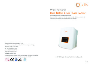
capability. According to the design specification, the BT 152-400R was chosen. It has thefollowing characteristics:321400200The designed values of gate triggering current,and gate triggeringvoltage,gt are8.564mA and 856.4mV respectively.120 Conduction SequenceIn this method, each SCR conducts for 120 .Only two SCRs remain ON at anyinstance of time. The gating signals for the SCRs were obtained as explained in section 5.1and the conduction sequence is 61, 12, 23, 34, 45 and 56. The expected three -phase inverteroutput is as shown in fig5.110.5Vd V060 120 240 300 360 420 480 Time-0.5VdV0.5Vd060 120 240 300 360 420 Time-0.5Vd0.5VdVoltage0Time (period)60 120 240 300 360 420 -0.5VdFig.5.10 The desired output waveforms for phase voltage,andThe motor sees sinusoidal waveforms as shown in fig5.1124
Fig.5.11 Three-phase sinusoidal waveformsThe red, green and blue lines represent the red, yellow and blue phases respectively. The blueand green waveforms lag the red waveform by 120 and 240 respectively. The simulationresults
inverter drive for a synchronous motor. The issues addressed in this paper include the design specifications, design of ac to dc converter, design of gate firing circuit, commutation circuits, inverter and LC filters. The results from both the simulations and the experimental

![Welcome [s3-ap-southeast-2.amazonaws ]](/img/28/wmi5140-user-manual.jpg)