Transcription
DEVELOPMENT OF A LARGE SCALE, SMART, MULTI-PURPOSEVIRTUAL ENVIRONMENT (SCIENCES BUILDING OF TUC) USINGGAME ENGINEByStefan PetrovskiSubmitted to theDepartment of Electronics and Computer EngineeringTechnical University of CreteExamining CommitteeDr Aikaterini Mania, AdvisorDr Aggelos BletsasDr Antonios Deligiannakis1
Table of Contents1Introduction . 91.12Technical Background . 132.1Introduction .132.23D computer graphics .132.2.1Modeling . 142.2.2Layout and animation . 142.2.3Rendering. 142.32.3.13D Models .14Modelling Process. 152.4Texturing – Importance of texture maps .162.5Game Engines .202.5.12.63Thesis Outline .11Game Engine Components . 21Three Modern Game Engines.212.6.1Unity 3D . 222.6.2Torque 3D . 222.6.3Unreal Development Kit (UDK) . 22Software Architecture and Development Framework . 243.1Unreal Development Kit .243.1.1Rendering Engine . 243.1.2Sound Engine . 253.1.3Physics Engine. 253.1.4Unreal Editor. 253.1.5Unreal Kismet . 283.1.6Material Editor . 293.1.7Sound Editor . 303.1.8Unreal Matinee . 313.1.9Unreal Lightmass . 313.2UnrealScript .323.2.1The Unreal Virtual Machine . 333.2.2Class Hierarchy. 343.2.3Timers . 352
3.2.4States . 363.2.5Interfaces . 363.2.6UnrealScript Compiler. 373.2.7UnrealScript Programming Strategy . 373.2.8Configuration Files . 383.2.9DLL Files . 393.2.10Input Manager . 393.2.11Materials in UDK . 403.33.3.1Flash Applications . 433.3.2Authoring Environment for Interactive Content. 443.3.3ActionScript 3.0. 453.4Connecting using Kismet:. 483.4.2Connecting using - Unrealscript:. 483.5.13.6Autodesk 3ds Max .49Predefined primitives . 50Setting up the Environment .513.6.1Setting up Scaleform GFx. 513.6.2Setting up Microsoft Visual Studio with nFringe . 52Virtual Environment Creation . 534.1World Geometry .534.1.1BSP . 574.1.2Static Meshes . 584.1.3Importing the Static Meshes. 624.2Materials .644.2.1Textures Vs Materials . 644.2.2Textures . 644.2.3Material Creation . 654.35Connection of the Graphical User Interfaces (GUIs) with the Application .473.4.13.54Scaleform GFx .41Doors .67Functionality Creation (Scripting) . 705.1The Three Fundamental Classes.705.2Application Data .745.3Detecting Focused Actors .773
5.4Lifts.795.5Menu System .985.6Heads-Up Display (HUD).1035.6.1Mini Map. 1095.6.2Extended Info Panel . 1135.75.7.1Creation of the Professor Info Interface using Flash and ActionScript 3.0 . 1205.7.2Connecting the User Interface with the application - UnrealScript. 1245.86Displaying Professor Information .119Path Finding .1275.8.1Setting Up the Navigation Network . 1295.8.2Target Nodes. 1315.8.3Connection of the UI. 1325.9Interactive Map .1405.10Reading Sensors Data From a Web Server.1475.10.1Display Panels . 1495.10.2Connecting to a web server. 152Conclusions and Future Work . 1566.1Implications for Future Work .1567Bibliography - References . 1588Appendix A . 1608.1Settings .1608.2Cinematics.1634
List Of FiguresFigure 2.1. Virtual Environment [Team Bunraku] . 13Figure 2.2. 3D polygonal modeling of a human face . 15Figure 2.3. An example of Curve Modeling. 16Figure 2.4. 3D model without textures (left), The same model with textures (right) . 16Figure 2.5. Examples of multitexturing. 1) Untextured sphere, 2) Texture and bump maps, 3) Te . 17Figure 2.6. Specular Map applied on a 3D ball. 18Figure 2.7. Wall with Normal Map applied . 19Figure 2.8. Mesh with diffuse map only (left). Opacity texture applied on the mesh (right) . 19Figure 2.9. Architecture of a game engine. 20Figure 3.1. The Unreal Editor with a virtual scene loaded. 26Figure 3.2 Static Mesh Editor . 27Figure 3.3. Properties of a Static Mesh Actor instance . 27Figure 3.4. Unreal Kismet with a simple sequence . 29Figure 3.5 The Material Editor with a sample material . 30Figure 3.6 The Sound Editor with a simple sound sequence loaded. 31Figure 3.7. Animating pocket door (left) using the Unreal Matinee Editor (right). 31Figure 3.8 UnrealScript Class Hierarchy . 35Figure 3.9. Scaleform design workflow . 43Figure 3.10. Flash Authoring environment with a Flash User Interface loaded . 44Figure 3.11. Initiation of a Flash User Interface Application through Unreal Kismet. 48Figure 3.12. 3DS Max's User Interface. 50Figure 3.13. 3ds Max Standard Primitives: Box, Cylinder, Cone, Pyramid, Sphere, Tube and Torus. . 51Figure 3.14. 3ds Max Extended Primitives: Torus Knot ChamferCyl, Hose, Capsule, Gengon and Prism . 51Figure 4.1. The Sciences Building of TUC . 53Figure 4.2. Floor plan of the first floor. 54Figure 4.3. South elevation of the ECE department . 54Figure 4.4. The redundant lines are removed . 55Figure 4.5. Floor plan imported into Max . 55Figure 4.6. The new closed line . 55Figure 4.7. The final 3D extruded object . 56Figure 4.8. The place holder imported into UDK. 56Figure 4.9. Application's BSP geometry (lit mode) . 57Figure 4.10. Application's BSP geometry (wireframe mode) - Additive Brushes (blu . 57Figure 4.11. Simple 3D object with material applied to it . 59Figure 4.12. The UVW unwrapping of an object in 3ds Max. This UV channel is. 60Figure 4.13. Setting a pivot point of a 3D model. 61Figure 4.14. Some of the created static meshes . 61Figure 4.15 Importing external 3D model into UDK . 62Figure 4.16. Stair rails 3D model with a simple collision applied on it . 635
Figure 4.17. Collision data created from blocking volumes (pink lines) . 64Figure 4.18. Normal Map creation workflow . 65Figure 4.19. Creating new material in UDK . 66Figure 4.20. On the left is a grey matte material, with no specular color. On the right. 66Figure 4.21. A material for the wooden floor surface with a normal map d . 67Figure 5.1 TUC Lift . 80Figure 5.2. An example of external Lift Button. The user has to be located in green cylind . 81Figure 5.3. When the user looks at the lift button informative box is displayed . 82Figure 5.4 Lift Control Panel. 87Figure 5.5 An example of lift creation . 97Figure 5.6. The HUD. 104Figure 5.7. The HUD flash file. 105Figure 5.8. Info panel . 114Figure 5.9. The detecting volumes . 115Figure 5.10. The user interface of the Find Path functionallity. In order to start path finding th . 128Figure 5.11. The green arow shows the way to the selected destination location. 129Figure 5.12. The Navigation Network consist of interconnected PathNodes (apples). 129Figure 5.13. The data from the sensors . 1476
AbstractThis thesis explores a method of three-dimensional fully interactive architecturalvisualization based on a game engine and presents a framework for creating suchvirtual environments. Through an examination of the tools and the components of agame engine, this thesis shows how a game engine can be used for creating large,smart and interactive Virtual Environments (VEs). The final product of this thesis,along with the research presented here, is a 3D computer application whichsimulates a real-time Virtual Environment (The Sciences building of TUC). Thecreated application simulates a real-time 3D navigable environment which the usercan interact with, navigate in it and view information related to spatial location ofthe faculty offices, labs or classrooms. Moreover, the user can view data fromexternal sensors which could be streamed in the interactive application dynamically.The goal of the application is to show the results of modern 3D architecturalvisualization using a game engine, as well as to build functionality that helps theusers in navigation and getting to know the university building simulated. Inaddition to this, many of the classes created can be used by developers to addinteresting functionalities to their VEs.7
AcknowledgementsI owe sincere thankfulness to my research advisor, Katerina Mania, who made mebelieve in myself and guided me through the whole process of thesis writing. I amsure that this thesis would not have been possible without her support,understanding and encouragement I felt when working on my project.I would like to express my gratitude to Prof. Aggelos Bletsas and to EleftheriosKampianakhs and Kostantinos Tountas for their invaluable help constructing andinstalling the sensors as well as for the implementation of the software used tosend data to the web server.Finaly, i would like to show my gratitude to my parents, friends and colleagues fortheir help and moral support. I would like to thank my sister for her patience andher help improving the readability of my thesis.8
1 IntroductionThe history of video games goes back to 1962 when a young computer programmerfrom MIT, Steve Russell created the first popular computer game Starwar. Starwarwas almost the first computer game ever written, however, they were at least twofar-lesser known predecessors: OXO (1952) and Tennis for Two (1958). Since then,video games have become so popular that over the past 30 years, they havebecome an integral part of our culture, and eventually led to more sophisticatedtechnology for their further development. Their popularity was a major cause forcontinuously increasing budgets in that sector and consequently for thedevelopment of sophisticated technology (Game Engines) for creating these games.This has resulted in the development of tool sets integrated with programminginterfaces we now call game engines that also support the development of real-timevirtual environments.Virtual Environments (VEs) allow us to explore an ancient historical site, visit a newhome led by a virtual estate agent, or fly through the twisting corridors of a spacestation in pursuit of alien prey. They simulate the visual experience of immersion ina 3D environment by rendering images of a computer model as seen from anobserver viewpoint moving under interactive control by the user. If the renderedimages are visually compelling, and they are refreshed quickly enough, the userfeels a sense of presence in a virtual world, enabling applications in education,training simulation, computer-aided design, electronic commerce, entertainmentand medicine.This thesis explores a method of three-dimensional fully interactive architecturalvisualization based on a game engine. Through an examination of the tools and thecomponents of a game engine, this thesis shows how a game engine can be usedfor creating large, smart and interactive Virtual Environments (VEs).3D Architectural visualization has been traditionally limited to static animation inthe sense that although the images display movement, the movement is alwaysfrom the same point-of-view. Such animations are frequently pre-rendered and notinteractive - [Kevin Conway, 2011].The final product of this thesis, along with the research presented here, is a 3Dinteractive computer application which simulates an existing university buildingnamed 'The Building of Sciences' of the Technical University of Crete (TUC), inChania, Crete, Greece.Application9
The created application simulates a real-time 3D navigable environment which theuser can interact with and view information related to spatial location of facultyoffices, labs or classrooms. Moreover, the user can view data from externalsensors, which could be streamed in the interactive application dynamicallyThis virtual 3D environment represents the Sciences Building of Technical theUniversity of Crete (TUC) and it is built using the Unreal Development Kit gameengine. In order to match the real building (scale and position of the walls, doors,windows etc.) as close as possible, the building's architectural floor pans, as well asphotographs, were used. Figure x.x shows the virtual environment.The goal of the application is to show the results of modern 3D architecturalvisualization using a game engine, as well as to build functionality that helps theusers in navigation and getting to know the building. In addition to this, many ofthe classes created can be used by developers to add interesting functionalities totheir VEs.The main features provided by this application are listed below: Navigation: The user navigates through the world interacting with thecontrolable parts such as doors, elevators, menu system, popups interfaces. Display: A Simple and minimalistic yet intuitive and fully functional HUD isdisplayed while using the application.10
Menu System: A User-Friendly menu from which various functionallities canbe initiated, such as, Path Finding, Interactive map, Cinematics etc. 3D User interfaces: A 3-layer, rotating user interface is implemented todisplay information related to faculty loaded from external files. Interactive Map: A 2D map of the building with buttons and images on it,that depicts the building's structure. Data from external sensors such as, current classroom temperature andpresence detection are streamed in the application. Mini Map Functionality. Path Finding Functionality.Navigation SystemThe user navigation system used in the application is the widely adapted WASDkebord layout. WASD is controlled as follows: W and S control the user’sforward/back movement and S and D control left and right strafing. The mouse isused to look around the environment and the left mouse button (LMB) is controllingthe user’s interactions with the Menu System.1.1 Thesis OutlineThis thesis is divided into seven chapters, which will be outlined below.Chapter 2 - Technical Background: This chapter reviews the process of creating3D computer graphics and presents the basic tools for creating interactive VEs. Itfirst shows two basic techniques for creating 3D objects and then introduces thereader to texture mapping. Furthermore, this chapter reviews the main componentsof a game engine, and at the end compares three state-of-art engines.Chapter 3 – Software Architecture and Development Framework: Thischapter describes the main tools used for creating the 3D application. It reviews thecore components and tools of the Unreal Development Kit (UDK) game engine andit presents the scripting language - Unrealscript that is used for adding functionalityto the VE. Apart from this, it introduces the technology used for creating UserInterfaces (UIs) and how it can be connected to the application.11
Chapter 4 - Virtual Environment Creation: This chapter desribes the wholeprocess of creating the virtual environment, starting from creating the neededassets (static meshes, textures) to their asseble in the UDK and adding collisionand materials to them.Chapter 5 - Implementation (Scripting): This chapter thoroughly describesevery aspect of creating the functionalities that the application supports throughcode, explaining and images.Chapter 6 - Conclusion and Future Work: The final chapter presents conclusions resulting from the thesis, as well as hints about future work.12
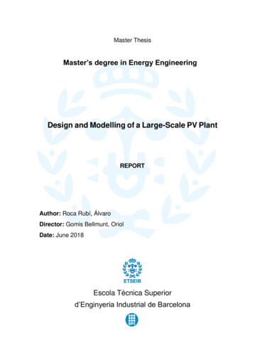
2 Technical Background2.1 IntroductionA Virtual Environment (VE) is a computer simulated scene which can beinteractively manipulated by users. Typical scenes used in such environmentsgenerally comprise of geometric 3D models, shades, images and lights which areconverted into final images through the rendering process. The rendering processmust be conducted in real time in order to provide scenes which are updatedreacting to user interaction.Figure 2.1. Virtual Environment [Team Bunraku]In this chapter the technologies and the methods used for creating 3D VirtualEnvironments (VEs) are discussed.2.2 3D computer graphics3D computer graphics are those that use a three-dimensional representation ofgeometric data. This data is stored in the computer so that performing calculationsand rendering 2D images is assured.3D computer graphics creation is a three step process: First comes 3D modeling , which is the process of forming a computer modelof an object's shape13
The second step includes layout and animation, that is the motion andplacement of objects within a sceneThe third step is 3D rendering . This basically includes the computercalculations that, based on light placement, surface types, and otherqualities, generate the image.2.2.1 ModelingThe model actually describes the process of forming the shape of an object. Thetwo most common sources of 3D models are those that an artist or engineeroriginates on the computer with some kind of 3D modeling tool, and modelsscanned into a computer from real-world objects. Basically, a 3D model is formedfrom points called vertices that define the shape and form polygons. A polygon isan area formed from at least three vertexes (a triangle). The overall integrity of themodel and its suitability to use in animation depend on the structure of thepolygons.2.2.2 Layout and animationBefore rendering into an image, objects must be placed in a scene. This definesspatial relationships between objects, including location and size. Animation refersto the temporal description of an object, i.e., how it moves and deforms over time.Popular methods include keyframing, inverse kinematics, and motion capture. Acombination of these techniques is often used in practice.2.2.3 RenderingRendering is the process of generating an image from a model (or models in whatcollectively could be called a scene file), by means of computer programs. A scenefile co
development of sophisticated technology (Game Engines) for creating these games. This has resulted in the development of tool sets integrated with programming interfaces we now call game engines that also support the development of real-time virtual environments. Virtual Environments (VEs) allow us to explore an ancient historical site, visit a new