Transcription
Next Generation FireTest Burner forPowerplant FireTesting ApplicationsInternational Aircraft Systems FireProtection Working GroupDresden, GermanyMay 12 - 13, 2015Steve SummerFederal Aviation AdministrationFire Safety Branchhttp://www.fire.tc.faa.govFederal AviationAdministration
Background Numerous FAR’s mandate fire protection in aircraft powerplant fire zones– Parts 23, 25, 27, 29, 33 – FAR Part 1 Section 1.1 – Definitions and Abbreviations Fireproof-– (1) With respect to materials and parts used to confine fire in a designated firezone, means the capacity to withstand at least as well as steel in dimensionsappropriate for the purpose for which they are used, the heat produced whenthere is a severe fire of extended duration in that zone;– (2) With respect to other materials and parts, means the capacity to withstandthe heat associated with fire at least as well as steel in dimensions appropriatefor the purpose for which they are used. Fire resistant-– (1) With respect to sheet or structural members means the capacity towithstand the heat associated with fire at least as well as aluminum alloy indimensions appropriate for the purpose for which they are used; and– (2) With respect to fluid-carrying lines, fluid system parts, wiring, air ducts,fittings, and powerplant controls, means the capacity to perform the intendedfunctions under the heat and other conditions likely to occur when there is a fireat the place concerned.– No definition of test method, apparatus, or criteria– Advisory material has been used to define these test parametersPowerplant Fire Test DevelopmentMay 12, 2015Federal AviationAdministration2
Background Advisory Circulars and FAA Reports:– Power Plant Engineering Report No. 3A, Standard Fire TestApparatus and Procedure (For Flexible Hose Assemblies), RevisedMarch 1978 Acceptable fire test burners listed in Appendix III:– Lennox OB-32 (not available)– Carlin 200 CRD (not available)– Stewart-Warner HPR 250 (not available)– Stewart-Warner FR-600 (not available)– AC 20-135, Powerplant Installation and Propulsion SystemComponent Fire Protection Test Methods, Standards, and Criteria,2/6/90 Acceptable fire test burners listed in sec. 6c:– Those listed in Appendix III of Powerplant Report 3A– SAE 401 Burner adjusted to 9.3 BTU/ft2s (propane fueled burner)– Propane and oxy-acetylene torch-standard and diverging nozzles (forsmall components)Powerplant Fire Test DevelopmentMay 12, 2015Federal AviationAdministration3
Background Advisory Circulars and FAA Reports (cont.):– FAA Aircraft Materials Fire Test Handbook (4/2000) Chapter 11 specifies the oil burners listed above, plus– Park DPL 3400 (not available) Chapter 12 specifies the oil burners above, including the Park DPL 3400– Chapter 12 Supplement, section 12.3.1 states:» SAE AS401B Propane Burner is also acceptable provided thetemperature profile and heat flux density conform to the specifiedrequirements– AC 33.17-1A, Engine Fire Protection, 8/3/09 References Powerplant Report 3A and AC 20-135 for acceptable burners All of these specified oil burners are no longer commerciallyavailablePowerplant Fire Test DevelopmentMay 12, 2015Federal AviationAdministration4
Background Industry is left with the propane burner, which can be obtainedand is typically preferred due to it’s consistency and ease of use– Intent of regulations is to provide protection against an enginefire, with flames from aviation flammable fluids such as oil, jet fueland hydraulic, not a propane flame– Propane and engine flammable fluid flames, despite havingsimilar measured temperatures and heat flux, are fundamentallydifferent– Propane will provide a less severe flame than an engineflammable fluid flame, due to the transparency of the propaneflame vs. the opacity of engine flammable fluid flame As test components approach the flame temperature, they begin tore-radiate due to the high surface temperature Heat is lost readily from the hot surface through the transparentpropane flame Heat is not lost through the opaque engine flammable fluid flamePowerplant Fire Test DevelopmentMay 12, 2015Federal AviationAdministration5
Background (cont.) This difference has been recognized by theauthorities FAA Tech Center Fire Safety Branch has beentasked by Transport Airplane Directorate to developburner performance standards for the nextgeneration fire test burner for powerplant firetesting– New burner should be much easier to calibrate, provide moreconsistent results, and be readily available for industry use.Powerplant Fire Test DevelopmentMay 12, 2015Federal AviationAdministration6
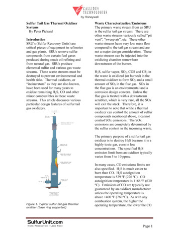
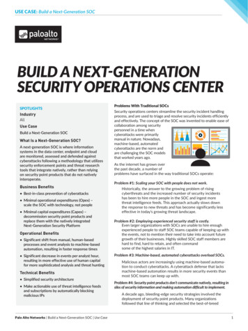
Current StatusReport PublicationPowerplants UserSurveySetting of NextGenBurner ParametersUsed to gain insight intocurrent calibration/operating conditions.Additionally, requestedtest data will help toinitially set NextGenburner settings.Utilizing the test dataobtained from Oil/Propane burner testing,NextGen burnerparameters will be set.Testing will be conductedto compare NextGen withOil/Propane burners.Round Robin TestingThis initial round robin testing,along with the test datarequested in the survey will aidin the initial setting of operatingparameters of NextGen Burner.Powerplant Fire Test DevelopmentMay 12, 2015An FAA report will bepublished detailing theNextGen burner settingsand performancecharacteristics. Thisreport will also detailtesting and calibrationguidelines/procedures forthe NextGen burner.Additional Round Robin/NextGen TestingAdditional round robin testingwith more advancedcomponents will be conductedand compared with NextGenburner performance to helprefine NextGen burner settings.Revision of AC 20-135Once a powerplants testmethod utilizing the NextGenburner has been defined andstandardized, a revision of AC20-135 and other regulatorymaterial will be able toproceed.Federal AviationAdministration7
Participating Labs Materials were sent to 8 different labs (9burners) for comparative testing– 1 lab utilizing a Blue Angel burner Set up with same tube, stator and turbulator as Park– 2 labs utilizing Park burner– 2 labs utilizing Carlin burner– 4 labs utilizing Sonic burner 1 lab utilizing both Park and Sonic In large test cell ( 1000 m3) In small test cell ( 100 m3)Powerplant Fire Test DevelopmentMay 12, 2015Federal AviationAdministration8
Materials Tested Slug Calorimeter– 10″x10″ copper panel with thermal absorptivecoating on front face and thermocouple on back faceto determine heat flux (Q mCp T). Panel wasmounted on a 24″x24″ steel plate.– Copper slug exposed to burner flame for a period of10-20 seconds.– Repeated 3x with sufficient time for full cooling of allmaterials (burner, thermocouples copper panel, etc)between each test.Powerplant Fire Test DevelopmentMay 12, 2015Federal AviationAdministration9
Materials Tested 1/8″ thick, 24″x24″ 2024 Aluminum Sheet– Burnthrough time recorded and reported– Repeated 3x Double-layered TexTech felt (to be mountedin a 24″x24″ opening)– Burnthrough time recorded and reported– Repeated 3xPowerplant Fire Test DevelopmentMay 12, 2015Federal AviationAdministration10
Powerplant Fire Test DevelopmentMay 12, 2015Federal AviationAdministration
Sonic Burner Parts/Setup Modified draft tubeSpacer tubeStatic plateBeckett model F31flame retention head(FRH) Delavan 2.5 gal/hr 80 W style fuel nozzle Burner conePowerplant Fire Test DevelopmentMay 12, 2015Federal AviationAdministration
Fuel Nozzle Delevan 2.5 gal/hr rated W stylefuel nozzles using a semi-solidspray pattern Once installed in the burner, thenozzles are to be flow checked,and fuel flow adjusted to 2.5gal/hr ( /- 0.1 gal/hr) All labs are advised to adjust theburner fuel pressure to achieve afuel flow rate to as close to 2.5gal/hr as possiblePowerplant Fire Test DevelopmentMay 12, 2015Federal AviationAdministration
Fuel Flowrate Check To properly check the fuel flow, a clear Tygon tubemust be slipped over the end of the fuel nozzleonce it is installed in the burner. A collectioncontainer AND graduated cylinder can be used tocollect the fuel. First ensure that the igniters areoff, and begin fuel flow through the Tygon tube intoa collection container. Once a steady stream isflowing, simultaneously move the Tygon tubing intothe graduated cylinder, and also start the timingdevice. It is recommended that fuel be collected fora 1-minute period.Powerplant Fire Test DevelopmentMay 12, 2015Federal AviationAdministration
Fuel Flowrate Check (con’t) At the 1-minute point, quickly divert the Tygon tubeaway from the graduated cylinder, back into thecollection container, to ensure that only 1 minute offuel is collected. Carefully measure the collectedfuel and convert this to gallons/hour. The fuel flowrate must be within 2.5 gal/hr ( /- 0.1 gal/hr). If it isnot within this range, adjust the fuel pressureaccordingly and repeat the process.Powerplant Fire Test DevelopmentMay 12, 2015Federal AviationAdministration
Ignition Wires Wires should be positioned exactly as shown in picture below tokeep them wrapped tightly around the fuel rail, and minimizedisrupting the flow of air in the draft tube It is important to ensure each wire crosses over or under the otherwire or fuel rod as shown Pull wires tight to eliminate any slack Wire lengths (tip of metal wire terminal to rear of draft tube)– Red: 12.5”– Black: 12.5”Powerplant Fire Test DevelopmentMay 12, 2015Federal AviationAdministration
New Ignition Wire Routing MethodPowerplant Fire Test DevelopmentMay 12, 2015Federal AviationAdministration
Igniters Igniter dimensions should be approximately the sameas those shown in the pictures belowDimensions shown in inchesPowerplant Fire Test DevelopmentMay 12, 2015Federal AviationAdministration
Standardized Igniter Position1/8” Gap between igniters– 1/8”1/4” Nozzle center to igniters– ¼” Nozzle face to igniter tips– 1/16”1/16”Powerplant Fire Test DevelopmentMay 12, 2015Federal AviationAdministration
Draft Tube Assembly Top: Modified draft tubewith machined groove (left),to allow for spacer sleeveand FRH Bottom: Spacer sleeve fitsinto draft tube to ensurestatic plate and fuel rod arecentered in draft tubePowerplant Fire Test DevelopmentMay 12, 2015Federal AviationAdministration
Draft Tube Assembly Top: FRH is press fit ontothe spacer sleeve Bottom: The FRH andspacer sleeve assembly ispressed into the burnerdraft tube until the face ofthe FRH and end of the drafttube are flushPowerplant Fire Test DevelopmentMay 12, 2015Federal AviationAdministration
Burner Installation It is possible for the staticplate to catch on the spacertube inside the draft tubewhile assembling theburner The draft tube assemblyshould be assembled withcare to prevent damaging ordislodging the static platePowerplant Fire Test DevelopmentMay 12, 2015Federal AviationAdministration
Burner SettingsPowerplant Fire Test DevelopmentMay 12, 2015Federal AviationAdministration
Sonic Burner Settings Face of FRH to nozzle tip: 1-1/8” Fuel nozzle adapter to static plate: 2-3/8” Static Plate Angle: centerline of igniters at 0 – Looking into the cone of the burner from above, the centerlinebetween the igniters will be at 0 on the burner reference plane– Fuel pressure: 100 psi /- 5 psi Note: This pressure is to be used as a starting point when flow checkingthe fuel flow rate. Actual pressure used during testing should be thatfound from the fuel flowrate check Air pressure: 50 psi Air Temperature: 50º 10ºF Fuel Temperature: 42º 10ºFPowerplant Fire Test DevelopmentMay 12, 2015Federal AviationAdministration
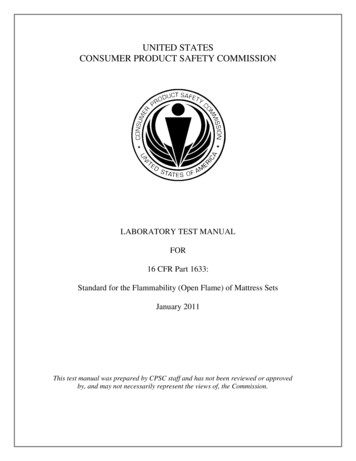
View from in front of Burner ConeBack Panel Side of Sample RigThermocouplesplaced 1″ abovecenterline with 1″spacing betweeneach T/CTC Rake Numbers7654321Air Supply Entering BurnerPowerplant Fire Test DevelopmentMay 12, 2015Federal AviationAdministration
Calibration All labs will calibrate using 1/8”, exposed bead, Type K, stainless steelsheathed thermocouples for calibrationLabs utilizing the Sonic Burner are not expected to necessarily achievethe calibration temperatures or heat fluxes, but rather are calibratingthe fuel/air temperature and pressure input to the burner. Temperatureand heat flux calibration data should be recorded and reportedhowever.Labs utilizing burners other than the Sonic Burner, should calibrate toa minimum average of 2000 F, with each thermocouple reading 2000 F 150 F. In addition, the burner should provide a heat flux density of atleast 9.3 BTU/ft2-s or 4500 BTU/hr as per AC 20-135.Changing or deviating from provided burner settings to achieve higheror more uniform calibration temperatures is not recommendedThree separate calibration runs should be recordedEach calibration should include a 2-minute warm-up of the burner, a 1minute thermocouple flame soak, and a 30-second data collectionperiod of flame temperature. This should be followed by the heat fluxcalibration.Powerplant Fire Test DevelopmentMay 12, 2015Federal AviationAdministration
Powerplant Fire Test DevelopmentMay 12, 2015Federal AviationAdministration
Powerplant Fire Test DevelopmentMay 12, 2015Federal AviationAdministration
Powerplant Fire Test DevelopmentMay 12, 2015Federal AviationAdministration
Powerplant Fire Test DevelopmentMay 12, 2015Federal AviationAdministration
Powerplant Fire Test DevelopmentMay 12, 2015Federal AviationAdministration
Powerplant Fire Test DevelopmentMay 12, 2015Federal AviationAdministration
Powerplant Fire Test DevelopmentMay 12, 2015Federal AviationAdministration
Powerplant Fire Test DevelopmentMay 12, 2015Federal AviationAdministration
Powerplant Fire Test DevelopmentMay 12, 2015Federal AviationAdministration
Powerplant Fire Test DevelopmentMay 12, 2015Federal AviationAdministration
Current Status – Testing Reconfiguring burner to current Materialsconfiguration – ignitor-less stator– Will repeat testing on materials to ensure repeatability,consistency with previous tests Building up to be able to conduct composite (andother) testing under vibration Need recommendations on composite suppliers,configuration, lay-up, etc to testPowerplant Fire Test DevelopmentMay 12, 2015Federal AviationAdministration37
Current StatusReport PublicationPowerplants UserSurveySetting of NextGenBurner ParametersUsed to gain insight intocurrent calibration/operating conditions.Additionally, requestedtest data will help toinitially set NextGenburner settings.Utilizing the test dataobtained from Oil/Propane burner testing,NextGen burnerparameters will be set.Testing will be conductedto compare NextGen withOil/Propane burners.Round Robin TestingThis initial round robin testing,along with the test datarequested in the survey will aidin the initial setting of operatingparameters of NextGen Burner.Powerplant Fire Test DevelopmentMay 12, 2015An FAA report will bepublished detailing theNextGen burner settingsand performancecharacteristics. Thisreport will also detailtesting and calibrationguidelines/procedures forthe NextGen burner.Additional Round Robin/NextGen TestingAdditional round robin testingwith more advancedcomponents will be conductedand compared with NextGenburner performance to helprefine NextGen burner settings.Revision of AC 20-135Once a powerplants testmethod utilizing the NextGenburner has been defined andstandardized, a revision of AC20-135 and other regulatorymaterial will be able toproceed.Federal AviationAdministration38
Current Status – AC 20-135 A sub-group had been formed with the goal of developingproposed rewording of AC20-135 in a parallel effort with NexGenburner development.– Testing requirements (i.e. when/how to vibrate sample, orientation ofsample, etc) and testing equipment (i.e. thermocouple type, heat transfercalibration device, etc) will be addressed.– Actual burner operation and calibration will be left open subject to burnerdevelopment. After initial sub-group meetings, it became evident that a moreformal involvement from FAA was required and it was suggestedthat a proposal be submitted to the FAA from industry with therequest that a formal group chartered for this task.Powerplant Fire Test DevelopmentMay 12, 2015Federal AviationAdministration39
Current Status – AC 20-135 (cont.) Dirk Kearsley (BAE Systems) has drafted thisrequest and has submitted to FAA (6/2014). Work is currently underway to form an internal FAAgroup of experts and interested parties to develop aplan of action. Internal FAA group is holding some initial meetingsto decide the best course forward. Resulting chartered group will likely be managedthrough the existing Systems Fire ProtectionWorking Group and Powerplants Fire Test TaskGroupPowerplant Fire Test DevelopmentMay 12, 2015Federal AviationAdministration40
QuestionsContact Information:Steve Summer609-485-4138Steven.Summer@faa.govPowerplant Fire Test DevelopmentMay 12, 2015Federal AviationAdministration41
Powerplant Fire Test Development May 12, 2015 4 Background Advisory Circulars and FAA Reports (cont.): - FAA Aircraft Materials Fire Test Handbook (4/2000) Chapter 11 specifies the oil burners listed above, plus - Park DPL 3400 (not available) Chapter 12 specifies the oil burners above, including the Park DPL 3400