Transcription
Frontier Boilers NationalBoard ListedEK1 Frontier and EK2 FrontierINSTALLATION & SERVICE MANUALGAS HEAT EDITIONManufactured By:Energy Kinetics, Inc.MH27877ANSI Z21.13-2005CSA 4.9-2005Low-Press Boiler51 Molasses Hill RoadLebanon, NJ 08833(908) 735-2066www.energykinetics.comASME certified by EKI.Certificate plate is underthe jacket on the steelvessel.INSTALLER:PLEASE HANG THIS INSTRUCTION MANUAL AND ACCESSORY INSTRUCTIONS VISIBLYNEXT TO THE BOILER USING THE SUPPLIED POUCH.CONSUMER:PLEASE RETAIN THIS INSTRUCTION MANUAL AND ACCESSORY INSTRUCTIONS FORFUTURE REFERENCE.Frontier Gas Heat – PN 10-2027 – January 2022
PLEASE READ THIS FIRSTSpecial Attention FlagsPlease pay particular attention to the following flags when you see them throughout this manual.DANGER:Notifies you of hazards that WILL cause severe personal injury, death or substantial property damage.WARNING:Notifies you of hazards that CAN cause severe personal injury, death or substantial property damage.CAUTION:Notifies you of hazards that WILL or CAN cause minor personal injury or property damage.NOTICE:Notifies you of special instructions on installation, operation, or maintenance that are important, but notnormally related to injury or property damage hazards.WARNING:If the information in this manual is not followed exactly, a fire or explosion mayresult, causing property damage, personal injury or loss of life.WARNING:Do not store or use gasoline or other flammable vapors and liquids in the vicinity ofthis or any other gas appliance.Provide unobstructed combustion air openings sized and located per boiler manualand applicable codes.WHAT TO DO IF YOU SMELL GAS Do not try to light any appliance. Do not touch any electrical switch; do not useany phone in your building. Immediately call your gas supplier from an outside phone. Follow the gas supplier’s instructions. If you cannot reach your gas supplier, call the fire department.WARNING:Installation and service must be performed by a qualified installer, serviceagency or the gas supplier.Retain this manual for use by your qualified service technician only.Should you observe unusual or abnormal operation of the burner orboiler, contact your qualified service technician immediately. Do notattempt to service or repair this product yourself.Frontier Gas Heat – PN 10-2027 January 20222
WARNING:Have the burner/boiler started up and serviced at least once annually by aqualified service technician. Professional care is necessary to properly serviceyour equipment and verify it is operating reliably. Failure to properly maintain theequipment could result in severe personal injury, death or substantial propertydamage.WARNING:You must keep the area around the burner/boiler free from the following. Failureto comply could result in severe personal injury, death or substantial propertydamage due to potential fire, explosion or equipment damage from corrosive flueproducts. Do not store or use gasoline or other flammable vapors or liquids near or inthe same room as the burner. Do not use or store laundry products, paint, varnish, thinner or other suchchemicals near or in the same room as the burner/boiler. These chemicalscause creation of acids in the burner, heat exchanger and vent system thatcan cause severe damage. Do not store combustible materials near or in the same room as theburner/boiler.GENERAL CARE AND MAINTENANCE Please read through the information provided for you in this manual. Ask your qualifiedservice technician to explain normal operation of your equipment. Daily inspect the space around the burner/boiler to verify the area is clean and free of thematerials listed above. Periodically watch the operation of your burner/boiler through an operating cycle to verifynormal operation. If you notice unusual conditions or equipment behavior, contact yourqualified service technician. Follow the instructions on the next page to shut down theburner/boiler while waiting for the technician.WARNING: Improper installation, adjustment,alteration, service or maintenance can causeproperty damage, personal injury (exposure tohazardous materials) or loss of life. Refer to theuser’s information manual provided with this boiler.Installation and service must be performed by aqualified installer, service agency or the gassupplier (who must read and follow the suppliedinstructions before installing, servicing, orremoving this boiler. This boiler contains materialsthat have been identified as carcinogenic, orpossibly carcinogenic, to humans).Frontier Gas Heat – PN 10-2027 January 20223
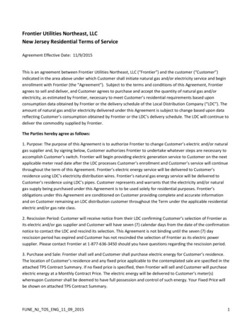
FOR YOUR SAFETY READ BEFORE OPERATINGWARNING:A.B.If you do not follow these instructions exactly, a fire or explosionmay result causing property damage, personal injury or loss of life.This burner does not have a pilot. It isequipped with an ignition device whichautomatically lights the burner. Do not tryto light the burner by hand.C. Use only your hand to turn the gas controlBefore OPERATING, smell all around theboiler area for gas. Be sure to smell next tothe floor because some gas is heavier thanair and will settle on the floor. See below.D. Do not use this boiler if any part has beenunder water. Immediately call a qualifiedservice technician to inspect the boiler andto replace any part of the control systemand any gas control, which has been underwater.WHAT TO DO IF YOU SMELL GAS Do not try to light any appliance. Do not touch any electric switch; do notuse any phone in your building Immediately call your gas supplier from aneighbor’s phone.Follow the gassupplier’s instructions. If you cannot reach your gas supplier, callthe fire department.knob. Never use tools. If the knob will notturn by hand, don’t try to repair it, call aqualified service technician.Force orattempted repair may result in a fire orexplosion.OPERATING INSTRUCTIONS1.2.3.4.5.6.STOP! Read the safety information above.Set the thermostat(s) to their lowest setting.Turn off all electrical power to the burner/boiler.This burner is equipped with an ignition device which automatically lights the burner.Do not try to light the burner by hand.Turn Gas control knob clockwiseto OFF.7.Wait five (5) minutes to clear out any gas. Then smell for gas, including near the floor. If yousmell gas, STOP! Follow the safety information above. If you don’t smell gas, go to the nextstep.8. Turn Gas control knob counterclockwiseto ON.9. Set thermostat(s) to desired setting.10. Turn on all electric power to the burner and boiler.11. If the burner/boiler will not operate, follow the instructions “TO TURN OFF GAS TO THEBURNER” below and call your service technician or gas supplier.TO TURN OFF GAS TO THE BURNER1.2.3.Set thermostat(s) to their lowest setting.Turn off all electric power to the burner and boiler if service is to be performed.Turn Gas control knob clockwiseto OFF. Do not force.Frontier Gas Heat – PN 10-2027 January 20224
TABLE OF CONTENTSEK1 Frontier and EK2 Frontier. 1INSTALLATION & SERVICE MANUAL . 1GAS HEAT EDITION . 1PLEASE READ THIS FIRST . 2TABLE OF CONTENTS . 5SCOPE . 6 SYSTEM 2000 FRONTIER BOILER . 7SYSTEM 2000 BOILER - PRINCIPLE of OPERATION . 7DIGITAL MANAGER - PRINCIPLE of OPERATION . 7RECEIVING and UNPACKING . 8LOCATION and CLEARANCE . 8CLEARANCE for CLEANING and SERVICE . 9COMBUSTION AIR . 9VENTING . 9CHIMNEY CONNECTOR .10CHIMNEY VENTING .10L-VENT CHIMNEY .10B-VENT CHIMNEY .11SIDEWALL VENTING .11VENTING MATERIALS .11REMOVAL FROM COMMON VENT SYSTEM .11GAS BURNER MOUNTING .12GAS BURNER SETTINGS .12GAS PIPING SYSTEMS .12GENERAL ASSEMBLY.13BOILER MOUNTING .13PIPING .15ZONE CONTROL .15FILLING WITH WATER, VENTING, and PURGING .16BOILER WATER TREATMENT .16ANTI-FREEZE.16WINTERIZING.16LINE VOLTAGE WIRING DIAGRAMS .17WIRING and CONTROLS .17ELECTRICAL CONNECTION - LINE VOLTAGE .18LOW VOLTAGE WIRING .18START UP PROCEDURE .24The AIR-FREE METHOD of MEASURING CO .25GAS BURNER OPERATION.25OUTPUT SIDE .272-Minute Energy Manager Diagnostic .28Step 1: .28Make sure you have no thermostat calls (turn thermostats down or disconnect after labeling zones).28Additional Manager Tests .29Line Voltage Relays .30Surge Suppression .30NOTE for sidewall vent systems: Add a 120VAC jumper from BURN to IND. This will run the inducer continuously,so caution should be used in systems without antifreeze.ANNUAL TUNE UP & INSPECTION .32Step 3 Inspect Flue Passage .33Annual Tune Up & Inspection .34Step 3 Open Front .34REPLACEMENT PARTS .35AMULET REPLACEMENT .35COMBUSTION CHAMBER REPLACEMENT .35Frontier Gas Heat – PN 10-2027 January 20225
RECORD OF INSTALLATIONINSTALLER NAME:INSTALLER ADDRESS:INSTALLER CITY, STATE:DATE INSTALLED:NOTES:SCOPEThis manual covers the Energy Kinetics System 2000 Frontier Boiler. The boiler is designed and equipped and hasbeen tested to generate hot water in a low pressure closed loop system. The boiler is a major component of a closed loopsystem that can be used as a heat source for hydronic, radiant, domestic hot water, spa, and/or pool heating systems. CallEnergy Kinetics to obtain piping and wiring instructions for applications, such as hydronic heating, radiant heating, domestichot water, swimming pool heating, multiple boilers, injection loops, etc. The installer of the system is responsible for thefinal design of the system and for adding the balance of the needed parts to complete the system.COMMONWEALTH OF MASSACHUSETTSWhen the boiler is installed within the Commonwealth of Massachusetts: This product must be installed by a licensed plumber If antifreeze is used, a reduced pressure backflow preventer device shall be used.INSTALLER NOTE:ALL INSTALLATIONS MUST BE MADE IN ACCORDANCE WITH ALL NATIONAL, STATE AND LOCAL,PLUMBING, HEATING AND ELECTRICAL CODES THAT MAY DIFFER FROM THIS MANUAL AND INACCORDANCE WITH THE FOLLOWING CODES, AS APPLICABLE:N.F.P.A. No. 70: National Electrical CodeCanadian Electrical Code, Part IA.N.S.I. / N.F.P.A. No. 211: Chimneys, Fireplaces, Vents and Solid Fuel Burning AppliancesA.N.S.I. Z223.1 / N.F.P.A. No. 54: National Fuel Gas CodeIf this gas fired boiler is converted to oil fired by field mounting a listed oil burner, then install in accordancewith A.N.S.I. / N.F.P.A. No. 31: Installation of Oil Burning EquipmentThese codes are available from:National Fire Protection Association1 Batterymarch ParkQuincy, MA 02269-9101.A hot water boiler installed above radiation level or as required by the Authority having jurisdiction, must beprovided with a low water cutoff device.A boiler should be installed in such a manner that, if the pressure vessel or any connection thereto should leak,the resulting flow of water will not cause damage to the area in which it is installed.A hot water storage tank should be installed in such a manner that, if the storage tank or any connection theretoshould leak, the resulting flow of water will not cause damage to the area in which it is installed.A boiler’s pressure relief valve, hot water storage tank T&P relief valve, backflow preventer, and all otherdevices must be piped to the nearest drain to avoid damage in the event the valve is actuated.Make sure relief discharge pipes from all reliefs are properly placed to safely contain discharge. Make surerelief discharge pipes, such as from a boiler or a hot water storage tank, will safely contain hot water and/orboiling water. Make sure relief discharge pipes, such as from a boiler or a radiant heating system, will safelycontain water treated with boiler chemicals and/or antifreeze. Reliefs include the boiler pressure relief valve, theback flow preventer discharge port, and the domestic hot water tank temperature and pressure relief valve. Anyother reliefs, such as from radiant heating systems, must also follow these guidelines.Frontier Gas Heat – PN 10-2027 January 20226
SYSTEM 2000 FRONTIER BOILERIMPORTANT MESSAGE TO HOMEOWNER: These instructions should be carefully read and kept for future reference togain the best performance from your System 2000 Frontier boiler.CONGRATULATIONS ON YOUR PURCHASE OF THE SYSTEM 2000 BOILER with its highly efficient low mass hydronicheat exchanger, the Energy Converter. It is the product of years of engineering and advanced design, which bringstogether in a single system all elements needed to provide efficient home heat. This operation and maintenanceinformation has been prepared so that you may better understand and use your Energy Kinetics Frontier Boiler andHeating System.SYSTEM 2000 BOILER - PRINCIPLE of OPERATIONSYSTEM 2000 comprises a heat source, the energy converter, circulating water and five (or more) zones controlled by anelectronic control, the Digital Manager.The Boiler sits cold until a thermostat calls for heat. The Digital Manager receives the call for heat and turns on themain circulator and burner. Water circulates within the boiler as it warms up to operating temperature. When ready, thezone valves open and deliver heat to the zones calling for heat. When the thermostats are satisfied, the Digital Managerturns off the burner and enters the energy recovery stage. The circulator and zone valve stay energized to deliver the heatremaining in the boiler to your home.When energy recovery is complete and the Boiler has been cooled off, the Digital Manager turns off the system andwaits for another thermostat (or tank aquastat) to call for heat. SYSTEM 2000 runs the burner only when you need heatand delivers that heat only where you need heat.The System 2000 Energy Converter is the product of advanced thermal engineering. It is designed with two separatepassageways, nearly 10 feet long, coiled around each other. Water travels along one passageway from your home towardthe center of the unit and heated gases travel from the unit center toward the chimney. This is a “forced circulation counterflow” design and it provides very efficient transfer of heat from the burning fuel to the circulating water. The superiorinsulation of the boiler minimizes heat losses to the surroundings, resulting in directing heat to your home in an efficient andquiet manner.SYSTEM 2000 has an extremely high annual efficiency (over 99% of steady state) because it runs only when yourhome needs heat. Energy recovery is completed at the end of each heat call, virtually eliminating off cycle losses.Your System 2000 holds a minimal quantity of water so it begins to supply heat in about 90 seconds. This rapidresponse means that your rooms can be heated quickly to temperature. The System 2000 EK-1 Frontier can heat water upto 100,000 BTU’s per hour and the EK-2 Frontier up to 200,000 BTU/hr.A modern power burner fires into the center of System 2000 where a high temperature, light weight ceramic chamberprovides ideal conditions for “near perfect” efficient, pollution-free combustion. Your System 2000 is tightly sealed so allproducts of combustion pass only to the chimney.The FRONTIER Boiler is designed with a hinged front cover that allows access to the inside of the boiler for inspectionand cleaning. All access for service is from the front, so the FRONTIER Boiler can be placed directly against a wall or intoa closet.DIGITAL MANAGER - PRINCIPLE of OPERATIONThe left side of the Manager is the input side, which provides 24-volt power supply and connections for thermostats.The right side is the output side, which starts the burner, circulator and zone valves or zone circulators. See photo of theManager on the cover.Lights on the Digital Manager indicate what is calling for heat (left side) and (right side) lights indicate active zone(s),burner operation and circulator operation. These function lights are an aid in servicing. The following is a typical cycle.1. SYSTEM WAITING FOR A CALL: The boiler is turned off and sits cold, waiting until a call for heat. The blue powerlight on the Manager is on.2. CALL FOR HEAT: A room thermostat call starts the cycle. The thermostat light on the left side will turn on for thatzone.3. PRE-HEAT: Output lights for the main circulator and burner turn on, the circulator starts, and the burner begins firing.The boiler water circulates through the energy converter via the bypass line, heating up the water.o4. HEAT: Once the boiler water has heated up to 150 F (about 90 seconds), the Manager will turn on the zone outputlight on the right side. The zone valve will open and hot water will flow to the zone needing heat. The burner runs aslong as there is a thermostat calling and as long as heat is being delivered to the zone. The burner may shut off if theooreturn temperature exceeds 170 F/190 F (RED burner light turns off) or if the high limit temperature is exceeded (REDburner light stays on, but the high limit aquastat shuts the burner off).5. ANOTHER CALL FOR HEAT: If another zone calls for heat while the burner is already running and the returnotemperature is above 150 F, the zone output will turn on, immediately supplying heat to the zone.Frontier Gas Heat – PN 10-2027 January 20227
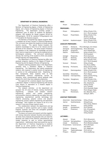
6. MONITOR RETURN TEMPERATURE: The Manager continually senses the return temperature and will turn off theoozone outputs if the return temperature drops below 120 F (130 F if Option Switch #1 is ON). With the zone outputsooclosed, the boiler water will quickly reheat and once the return temperature reaches 140 F (150 F if Option Switch #1is ON), then the Manager will reopen the zone valves.7. THERMOSTAT (or Aquastat) SATISFIED: The thermostat light on the left side will go out. The burner light and theburner will then turn off.8. ENERGY RECOVERY: The circulator and zone valve remain energized. The circulating water will remove the energyfrom the converter, sending the heat to the last zone that called. The energy recovery stage continues until the returntemperature has dropped sufficiently or until maximum timing has been reached. The boiler is now sitting cold, waitingfor the next call for heat. Maximum timing for heat recovery stage is usually set at twenty minutes for space heatingzones and is fixed at five minutes for Zone HW. (See Digital Manager Option Switch Settings).RECEIVING and UNPACKINGInspect shipment upon receipt for external damage. When unpacking and uncrating, inspect each item for internaldamage. Any damage found should immediately be reported to the freight carrier before installation. The receiver isresponsible for following the claims procedure of the freight carrier. The freight carrier is responsible for taking promptaction on all claims. If freight cannot be inspected at the time of delivery, sign the bill of lading “Subject to Inspection” andinspect the shipment as soon as possible after receipt. Replacements for parts damaged in shipment are available uponreceipt of a signed copy of a claim report (concealed damage claims should be filed immediately against the freight carrierby the consignee).After unpacking, check each item against the packing list. Inspect it thoroughly for loose parts, instruction sheets andpacking lists. Immediately report any missing items. It is wise to complete the installation before discarding packingmaterial. Store all parts where they will not be damaged or lost during installation.LOCATION and CLEARANCEDANGER: Provide clearance to combustible surfaces in accordance with all local and national codes. Follow NationalFire Protection Association Bulletin NFPA Installation of Gas Burning Equipment and all applicable codes.Installation Clearances from Boiler Surfaces, InchesClearance to CombustiblesFront of boiler15 1/2Left side of boiler body0Right side of boiler body0Back of boiler body4Top of boiler body16Bottom of boiler legs to floor0B-Vent (gas only): from flue pipe3L-Vent: from flue pipe3Standard Flue: from flue pipe9*Minimum recommended clearance to allow the door to fully open.Clearance for Service200041616*339Figure 1A. Top View of Boiler Flue Connection Clearance to Combustibles3”6"Boiler Weight and Water Content9”3”TYPICAL FLUE 1"CONNECTION2"TYPICAL FLUECONNECTION8"ModelWeightWater ContentAir Inlet Pipe SizeBoiler Flue Outlet(A) L-VENT OR PELLET VENT (B) STANDARD VENT PIPEFrontier Gas Heat – PN 10-2027 January 20228EK-1 Frontier270 lbs2-1/2 gallons2"4"EK-2 Frontier350 lbs4 gallons3"6"
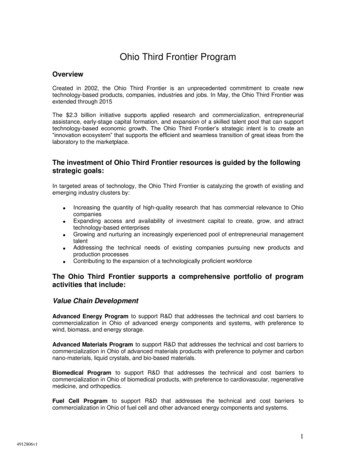
CLEARANCE for CLEANING and SERVICEInstallations should utilize one of Energy Kinetics boiler stands to provide a solid, level, and smooth foundation for theboiler. NOTICE: Do not install on carpeting. Place the unit as near to the chimney or vent as possible allowing clearancefor front cleaning and service as shown in Figure 1B. If not using an Energy Kinetics supplied stand, provide a solid, level,smooth, foundation with clearance for door opening and service. NOTICE: The stand must be level to allow for properventing of air from the boiler. The Frontier is manufactured with the BACK of the boiler higher than the front to assist in airEK1: 41" / EK2: 49"removal.EK1: 21-1/2"EK2: 29-1/2"* Height of Frontier on a Low Profile Base** Height of Frontier on a Standard Boiler Base24"11-5/8"SYSTEM 2000ENERGY MANAGERHOT WATERSRTEMP. S ENS.THWT1T2T3A1A2B9"T414Z4ZHWZ1Z2Z3INDUCER2 4VAC122334ENERGYKINETICSL eb an on , Ne w JerseyB URNERINDB1CIRCULA TORC AU TIONB2CIRCEK1: 41" / EK2: 49"EK1: 21-1/2"EK2: 29-1/2"24"12-3/4"30"SYSTEM 2000ENERGY MANAGERHOT WATERTHWT1T2T3A1A2RTEMP. S ENS.BST411223344INDUCERENERGYKINETICSL eb an on , Ne w JerseyC AU TIONB URNERZ4ZHWZ1Z2Z32 4VACINDB19"CIRCULA TORB2CIRC73"30"48"*56"**34"NOTE:Tank StandAllows The BoilerTo Be MountedOver Top Of a 40Gal Lo-Boy Tank.9"*17"**NOTE:All piping(hydronic, gas &inlet air) mustallow clearancefor door opening.29-1/4"COMBUSTION AIRFigure 1B – Boiler Clearance for Clearing and ServiceThe System 2000 Boiler must be installed in an area where adequate fresh air is available to support combustion. TheFrontier is provided with a sealed Air Box that can be piped to air outside the building. Piping of outside air directly to theboiler is highly recommended because it completely isolates the boiler from the home environment, as well as greatlyreducing operating noise from the boiler.Boiler with outside air piping: In modern houses with tight construction the connection of the Air Box to an outside airsource to provide combustion air is highly recommended. The outside air source must be located high enough above gradeto be at least 12” above expected snow accumulation.WARNING:For systems with sidewall venting, combustion air piping from outside the building is required. TheEnergy Kinetics sidewall vent kit contains
11. If the burner/boiler will not operate, follow the instructions "TO TURN OFF GAS TO THE BURNER" below and call your service technician or gas supplier. TO TURN OFF GAS TO THE BURNER 1. Set thermostat(s) to their lowest setting. 2. Turn off all electric power to the burner and boiler if service is to be performed. 3.