Transcription
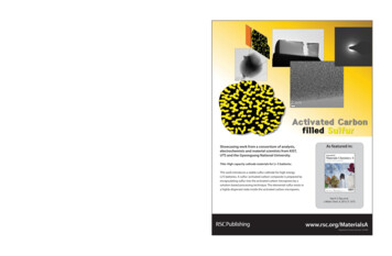
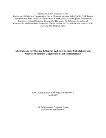
Sulfur Tail Gas Thermal OxidizerSystemsBy Peter PickardIntroductionSRU’s (Sulfur Recovery Units) arecritical pieces of equipment in refineriesand gas plants. SRUs remove sulfurcompounds from certain fuel gasesproduced during crude oil refining andfrom natural gas. SRUs produceelemental sulfur and various gas wastestreams. These waste streams must bedestroyed to prevent environmental andhealth risks. Thermal oxidizers, or“incinerators” as they are also known,have been used for many years tooxidize remaining H2S, CO and otherminor combustibles in these wastestreams. This article discusses variousparticular design features of sulfur tailgas oxidizers.Waste Characterization/EmissionsThe primary waste stream from an SRUis the sulfur tail gas stream. There areother waste streams variously called “pitvent”, “sweep air”, etc. These otherwaste streams have very low mass flowcompared to the tail gas stream and arenot a major design consideration. Thesewaste streams can be injected into theoxidizing chamber somewheredownstream of the burner.H2S, sulfur vapor, SO2, COS and CS2 inthe waste is oxidized (or burned) in thethermal oxidizer to form SO2 and a smallamount of SO3 in the flue gas. SOx inthe flue gas is an environmental and acorrosion design concern. Unless theflue gas is treated with a downstreamscrubber, which is very rare, all the SOxwill exit the stack. Therefore, it isimportant to note that while a thermaloxidizer can control the amount of sulfurcompounds mentioned above, it cannotcontrol SOx emissions. The SOxemissions are completely determined bythe sulfur content in the incoming waste.The primary purpose of a sulfur tail gasoxidizer is to destroy H2S because it is ahighly toxic gas, even in lowconcentrations. The specified H2Semission limit from an oxidizer typicallyvaries from 5 to 10 ppmv.Figure 1. Typical sulfur tail gas thermaloxidizer (base ring supported)In many cases, CO emissions limits arealso specified. H2S is much easier toburn than CO. H2S autoignitiontemperature is 529 ºF (276 ºC). COautoignition temperature is 1166 ºF (630ºC). Emissions of CO are typically notguaranteed by an oxidizer manufacturerunless the operating temperature isabove 1400 ºF (760 ºC). As with anycombustion system, the higher theoperating temperature, the lower the COPage 1
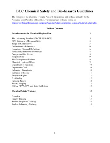
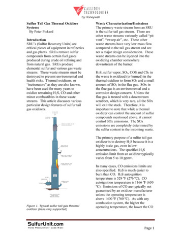
emissions. However, a higher operatingtemperature can result in higher NOxemissions.Low NOx fired heater burner technologyis frequently confused with thecapability of a thermal oxidizer burner.Ultra-low NOx burner technology usedfor fired heaters can not be applied toburners for thermal oxidizers. Thewidely varying applications encounteredin the supply of thermal oxidizersrequire a different design approach thanthat used for fired heater burners.For example, the use of flue gasrecirculation for NOx reduction is vastlydifferent for fired heater burners than forthermal oxidizer burners. Flue gasrecirculation associated with fired heaterburners is internal to the heater.However, flue gas recirculationassociated with a thermal oxidizer wouldhave to be external to the combustionchamber. The reason for externalrecirculation is due to the fact that thethermal oxidizer combustion chamber islined with refractory (without a heatsink) eliminating the availability ofcooled flue gas for internal flue gasrecirculation.Figure 2. Comparison of fired heaterburner and thermal oxidizer burnerOnly in thermal oxidizer applicationsutilizing a waste heat boiler downstreamcan one employ flue gas recirculation forNOx reduction in a thermal oxidizerexternal to the burner and oxidizerchamber. This is commonly known as,“external flue gas recirculation”. A slipstream of the flue gas downstream of theboiler can be recirculated back to theburner via a recycle fan. However, theducting, electrical power usage, largerplot space required and morecomplicated burner make this approachquite expensive and therefore rare.The NOx emissions from a thermaloxidizer will depend on various factorssuch as the allowable CO emission limit,the CO content in the tail gas, the fuelgas composition, the waste gascomposition and burner design.Typically, the NOx emissions will rangefrom 0.06 to 0.1 pound of NOx per1,000,000 Btu of heat released.Although flue gas recirculation cannotbe used to lower NOx emissions,Callidus has developed a “tool kit” ofthermal oxidizer burner designtechniques over the years. All thesemethods involve a way to lower theflame temperature and may include suchthings as staged fuel gas combustion,water injection and steam injection.These techniques have been used formany years by several companies.Callidus also has several otherproprietary techniques to reduce NOxlevels. These designs involve thevarious ways tail gas can be used to coolthe flame. Care must be taken in howtail gas is used to cool the flame. If theflame is cooled too much, CO emissionsmay increase. Experience, coupled withcomputational fluid dynamic modelingcan result in designs that can lower NOxby 10 to 20%Page 2
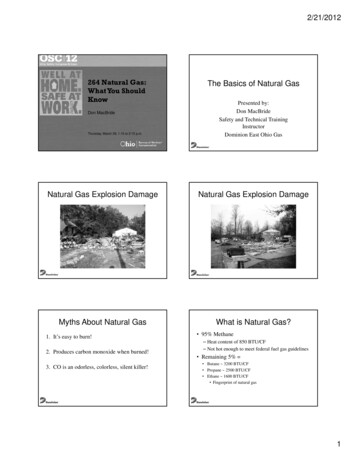
aluminum or galvanized carbon steel andstands off from the shell by 3 to 6 inches(75 to 150 mm). This shroud also calleda “rain shield” maintains a warm layer ofslow-moving air between the shroud andthe shell that keeps the steel hot but notas hot as external insulation. Externalinsulation would result in temperaturesbeyond the oxidizing temperature ofcarbon steel.Figure 3. Typical tail gas incinerator burnerCorrosionDue to the presence of SOx in the fluegas, care must be taken to prevent thesteel shell of the oxidizer from gettingbelow the dew point of the acid gas.Sulfuric acid can condense at very hightemperature in flue gas. The acid gasdew point in the flue gas from a sulfurtail gas incinerator is typically between300 and 350 ºF (177º C). Since thermaloxidizers furnaces are typically carbonsteel with a castable or brick refractorylining, care must be taken to keep thesteel temperature about 50 ºF (28 ºC)above the dew point in order to avoidcorrosion from dew point condensation.If it is not possible to keep the above thedew point, a coal tar mastic lining orother high temperature acid resistantpaint can be applied to the internalsurface of the carbon steel shell beforethe refractory is installed. Althoughcoatings are helpful, it only takes a smallimperfection in the coating to allow acidto penetrate and cause corrosion.Therefore, maintaining the temperatureof the steel above the dew point is themost reliable approach to preventcorrosion.To maintain steel shell temperatureabove SOx dew point, a thermal shroudis generally installed around the shell ofthe oxidizer. This shroud is typicallyPhysical OrientationOxidizers are usually vertical withhorizontally fired burners. Due to thepotential presence of liquid sulfur in thetail gas, the burner orientation ishorizontal to allow the sulfur to draininto the bottom of the incinerator vessel.Vertical, up-fired burners are neverrecommended since the liquid sulfurcould pool at the bottom of the chamberand fall into the combustion air plenumof the burner.Due to the presence of SOx in the fluegas, the stack outlet on sulfur tail gasoxidizers is typically 150 feet (46meters) or more above grade. Theheight of the stack is dictated by adispersion analysis for ground levelconcentration of SOx. Environmentalregulations dictate acceptable groundlevel concentrations. In order to performan accurate dispersion model analysis,knowledge of the surrounding terrainand adjacent structures is necessary.The stack and thermal oxidizer chamberare in many instances the same vessel.Stacks are typically self-supported bythe base ring but in some cases arederrick supported. Some of the derricksupported designs will be less expensivebut will require larger plot space andmore time to assemble in the field.Page 3
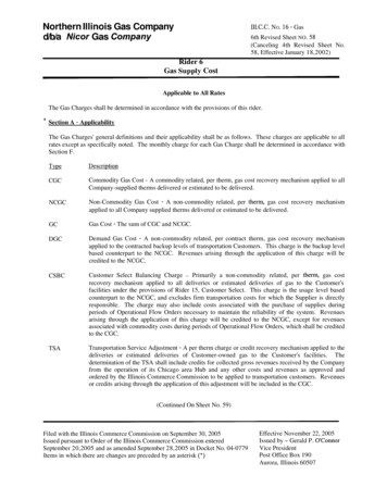
For large capacity systems, the oxidizerchamber is horizontal. If a verticaldesign were used, it would result in fuelgas flame impingement on the refractorywall opposite the horizontally firedburner. This is especially true if theburner is natural draft since the flamewill be longer than in a forced draftsystem.natural draft unit is lower than in aforced draft system. Combustion airturndown limits fuel gas burnerturndown which limits tail gas turndown.Combustion air turndown in a naturaldraft unit is between 2:1 and 3:1depending on the stack height.HI (High Intensity) BurnersHigh intensity burners require highcombustion air pressure drop, typicallyaround 1.5 psig (10.3 kPa). The designcauses the combustion air to swirlincreasing turbulence downstream. Thistype of burner, although rarely used bytail gas incineration, is frequently usedin applications in which it is important tohave a short flame and excellent mixingsuch as in sulfur reaction furnaces andreheat burners.At least 50% of the sulfur tail gasincinerators that Callidus has providedover the last 20 years are natural draft.Both medium intensity burners(moderately high pressure drop) andnatural draft burners (very low pressuredrop) have been used in tail gas serviceover the years with much success.Figure 4. Tail gas incinerator with a flareForced Draft vs. Natural DraftBurners can be natural draft or forceddraft depending on turndownrequirements and whether or not wasteheat recovery equipment is locateddownstream. It is generally notacceptable to supply a natural draftburner for a system with heat recovery.The pressure drop of the flue gasthrough a superheater or waste heatrecovery boiler is usually too great fornatural draft alone to overcome. Thecombustion air turndown available in aWhile a typical forced draft system witha waste heat boiler might require acombustion air fan discharge pressure of8” w.c. (2 kPa), the same system with anHI burner would require 60” w.c (15kPa). 7.5 times the electrical power isneeded to utilize a 400 HP (300 KW)motor instead of a 50 HP (38 KW)motor. Although most oxidizermanufacturers have the capability ofproviding both types of burners, thecompanies that promote HI burners fortail gas service only manufacture HIburners. In today’s search for costeffective, low energy solutions, the HIPage 4
burner might not be the most economicalsolution.Stack Sample PortsEnvironmental regulations requiresample ports be located after one secondresidence volume of the flue gas. This ismeasured from the centerline of theburner or the center line of the last wastegas nozzle to the center line of thesample port nozzle. Ideally, the sampleports should also be located in a straightrun of stack, eight diameters downstreamof last disturbance and at least 2diameters from the exit or downstreamdisturbance. The “disturbance” istypically a transition in diameter of thestack. If this ideal arrangement ispossible, then only two sample ports,located at 90 degrees around thecircumference of the stack are required.In cases in which it is not possible tohave eight diameters upsteam and twodownstream, or in cases in which it isnot economically feasible, it isacceptable to provide four sample portsoriented at 90 degrees around thecircumference of the stack. Of course,in this case a 360 degree sample portaccess platform is required. If the idealeight and two diameters cannot beprovided, more samples are usuallyrequired during the stack test.RefractoryThe refractory lining can be low ironcastable or brick. Brick refractory willprovide longer life than castable. Fibertype refractory (ceramic fiber, board ormodules) is not recommended. Acid gaswill quickly destroy fiber type materials.In addition, fiber type refractory is tooeffective an insulator and will result insteel shell temperatures that are belowthe dew point, even with a rainshield.Heat RecoveryOxidizer chambers with heat recoveryboilers are nearly always horizontal.Combustion air pre-heaters and wastegas pre-heaters are not recommended ina sulfur tail gas oxidizer system. Whencombustion air or waste gas is heatedwith the flue gas from the incinerator,the surfaces of the heat exchanger canbecome too cold on the flue gas side andcan lead to acid gas condensationcorrosion. Care must also be taken inthe design of a waste heat recoveryboiler to avoid corrosion. The flue gasexit temperature should not be so lowthat the flue gas could begin to condenseon the stack surface downstream.Typically, the boiler exit flue gastemperature is maintained at 400 to 500degrees F, depending on the boiler feedwater temperature and the steamtemperature needed to avoid corrosion.The stack downstream of a waste heatboiler is generally unlined carbon steelwith external insulation. The externalinsulation insures that the flue gasremains hot enough to not condense outany SOx or H2O as it rises through thestack. Near the exit the flue gas willunavoidably be close to the dew point orbelow. To avoid corrosion at the exit,the top 3 to 10 feet of the stack isspecified as stainless steel.Although occasionally considered, a fluegas bypass around the boiler is notrecommended. The required bypassvalve would be very large, expensive,prone to leak and could become aserious a maintenance problem.Fabrication and Design CodesSulfur tail gas incinerators are typicallydesigned to AISC or ASME code. ThePage 5
operating pressure ranges from 1 or 2inches water column vacuum to 8 to 10inches water column positive pressure(in the case of a system with a wasteheat boiler). ASME code design is notnecessary at these pressures. However,some customers prefer ASME code for asturdier design and higher qualityfabrication. A cost effectivecompromise is to design per AISC butspecify ASME fabrication.users with knowledge of designconsiderations important to the design ofthese systems. It should, also, allowsuppliers to avoid designs or designconsideration parameters that mightadversely affect the reliability of theseunits.Some SRU licensors anticipatedeflagration potential in the oxidizer. Insuch cases, the oxidizer chamber isfrequently designed for 50 psig perASME Code.Combustion Air Flow MeasurementThe best methods of measuring air flowdue to its typically low pressure and highflow are: pitot tube array, thermaldispersion or annubar. A pitot tube arraycan be the most cost effective since itrequires very few up- and down-streamdiameters for a good measurement. Ifthe air flow is very large, the number ofduct diameters required by other devicescan result in very large plot spacerequirement. Orifice plates aredefinitely not practical due to the highpressure drop required. A venturi metercan be used, but they are expensive,require more pressure drop (4” w.c. vsless than 1” w.c.) and take up morespace compared to the recommendedmethods.ConclusionTail Gas Incineration has been used asan effective means for disposal of wastegases produced in Sulfur RecoveryUnits. Information provided in thisarticle will be of interest and benefit toboth the user of this equipment and thosesupplying it. The article should provideFigure 5. Tail gas incinerator with heat recovery boilerPeter PickardChief Applications Engineer - Incineration DivisionCallidus Technologies by Honeywell7130 South Lewis, #335Tulsa, Oklahoma 74136 USAOperator 918-496-7599Direct Line 918-523-2171Mobile 918-809-7383peter.pickard@honeywell.comPage 6
Low NOx fired heater burner technology is frequently confused with the capability of a thermal oxidizer burner. Ultra-low NOx burner technology used for fired heaters can not be applied to burners for thermal oxidizers. The widely varying applications encountered in the supply of thermal oxidizers require a different design approach than