Transcription
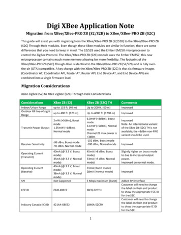
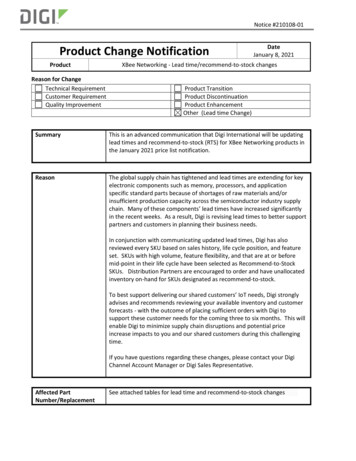
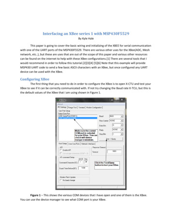
Interfacing an XBee series 1 with MSP430F5529By Kyle HaleThis paper is going to cover the basic wiring and initializing of the XBEE for serial communicationwith one of the UART ports of the MSP430F5529. There are various other uses for the XBee(ADC, Meshnetwork, etc.), but these are uses that are out of the scope of this paper and various other resourcescan be found on the internet to help with these XBee configurations.[1] There are several tools that Iwould recommend in order to follow this tutorial.[2][3][4] [5][6] Note that this example will provideMSP430 UART code to send a few basic ASCII characters with an XBee, but once configured any UARTdevice can be used with the XBee.Configuring XBeeThe first thing that you need to do in order to configure the XBee is to open X-CTU and test yourXBee to see if it can be correctly communicated with. If not try changing the Baud rate X-TCU, but this isthe default values of the XBee that I am using shown in Figure 1.Figure 1 – This shows the various COM devices that I have open and one of them is the XBee.You can use the device manager to see what COM port is your XBee.
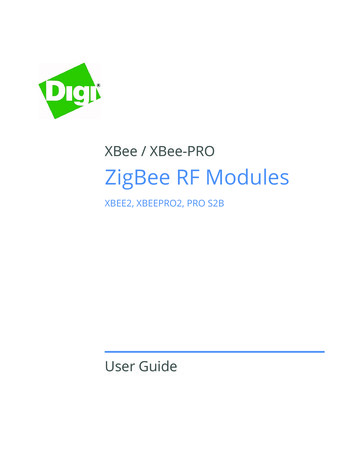
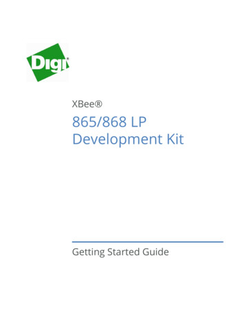
Figure 2 – After testing the XBee it should come back and show this message saying that it issuccessful.After doing this click on the Modem Configuration tab and click the read button. This will showyou the various settings and the current settings for the XBee. There are only a few settings that youmust change in order for the two XBee to communicate. The figure below highlights the specific settingthat need to be changed. In figure 3 there are four fields that you need to change. On both XBees youneed to make the channel and PAN ID exactly the same. On one XBee you need to make DestinationAddress an arbitrary number within the given range and make the 16-bit Source Address anotherdifferent arbitrary number within the given range. For instance, in XBee1 the DL field could be 11 the MYfield could be 10 and in XBee2 the DL field should be 10 the MY field should be 11.Figure 3 – In this figure the fields that need to be changed have squares around them.
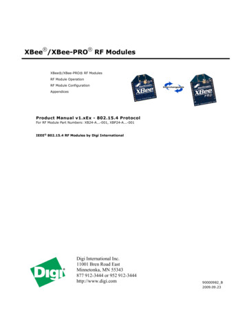
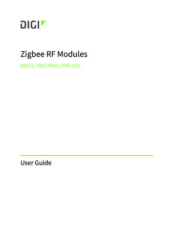
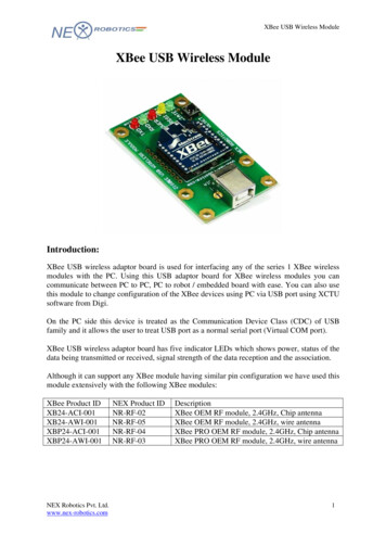
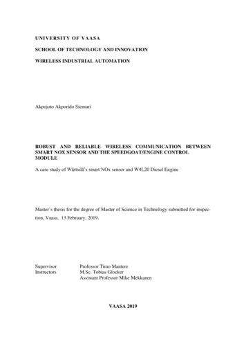
In Figure 4 below the fields that are pointed out must be the same as you configurationfor UART in you RX/TX module of you controller. In this case my Interface Data Rate(Baud Rate) is 9600baud and the Parity is set to no parity bit. Once you complete these few steps for both XBee modulesyou should wirelessly be able to transmit using serial communication from one serial device to another.You can use a terminal program such as Putty or X-TCU has a built in terminal functionality that you cantest you XBee’s with to see if they are properly configured before you try to use them with a controller.There is a basic code example provided for a MSP430F5529 sending the ASCII characters ‘A’ ‘B’ ’C’ to theUART port and when wired to the XBee it will be seen at the other XBee module’s RX pin.Figure 4 – This shows fields that you have to make sure are consistent with the UARTconfiguration in the MSP430.PinoutMSP430F5529RX (Pin 41)TX (Pin 40)XBeeTX (Pin 2)RX (Pin 3)VCC(Pin 1)GND(Pin 10)Table1 – This table shows the connections that need to be made from the Xbee to the MSP430F5529.
Code#include msp430f5529.h void main(void){WDTCTL WDTPW WDTHOLD;P3SEL BIT3 BIT4;UCA0CTL1 UCSWRST;UCA0CTL1 UCSSEL 2;UCA0BR0 0x68;UCA0BR1 0x00;UCA0MCTL UCBRS 1 UCBRF 0;UCA0CTL1 & UCSWRST;UCA0IE UCRXIE;// Stop WDT// P3.3,4 USCI A0 TXD/RXD// Reset the state machine// SMCLK// 1MHz/9600 0x68 (see Data Sheet for calculations)//// Modulation UCBRSx 1, UCBRFx 0// Initialize the state machine// Enable USCI A0 RX interruptwhile (!(UCA0IFG&UCTXIFG));UCA0TXBUF 0x41;while (!(UCA0IFG&UCTXIFG));UCA0TXBUF 0x42;while (!(UCA0IFG&UCTXIFG));UCA0TXBUF 0x43;bis SR register(GIE);no operation();// Is the USCI A0 TX buffer ready?// TX - A// TX - B// TX - C//interrupts enabled}// This is the RX UART ISR and is entered when the RX buffer is full#pragma vector USCI A0 VECTORinterrupt void USCI A0 ISR(void){//Insert Code for the RX interrupt}Parts Used[2] - 2 XBee 24-AUI-001/XB24-AUI-001-ND/935967[3] –1 XBee Explorer (To save money you can make your own PCB with a FTDI IC and some resistors)http://www.sparkfun.com/products/8687
[4] – 1 MSP430F5529(I used a target board found at the link below, but you can use the controller ofyour tId 1631Software[5] X-CTUhttp://www.digi.com/support/productdetail?pid 3352[6] Code wnload CCS#Code Composer Studio Version 5 DownloadsResourcesXBee Data igbee/XBee-Datasheet.pdfMSP430F5529 Family .pdfRecommended Material[1] - http://xbee.wikispaces.com/
MSP430 UART code to send a few basic ASCII characters with an XBee, but once configured any UART device can be used with the XBee. Configuring XBee The first thing that you need to do in order to configure the XBee is to open X-CTU and test your XBee to see if it can be correctly communicated with.