Transcription
UNITED STATESCONSUMER PRODUCT SAFETY COMMISSIONLABORATORY TEST MANUALFOR16 CFR Part 1633:Standard for the Flammability (Open Flame) of Mattress SetsJanuary 2011This test manual was prepared by CPSC staff and has not been reviewed or approvedby, and may not necessarily represent the views of, the Commission.
Laboratory Manual: 16 CFR Part 1633 Standard for the Flammability (Open Flame) of Mattress SetsTABLE OF CONTENTS1. SCOPE .32. SUMMARY OF 16 CFR PART 1633 STANDARD .33. PERFORMANCE REQUIREMENTS .34. GENERAL EQUIPMENT LIST .45. TIMELINE .56. SAFETY .67. SPECIMEN INSPECTION .68. SAMPLE CONDITIONING .69. CALIBRATION OF TEST INSTRUMENTS .79.1 Calorimetry Hood .79.2 Propane Flow Control System .710. TEST PREPARATION .1110.1 Test Area Conditions .1110.2 Prepare Test Floor Area .1110.3 Camera Placement .1110.4 Burner Assembly Inspection .1311. SETTING BURNER TIMERS .1711.1 For Calibration of Propane Flow Control System .1711.2 For Testing .1712. DATA COLLECTION .1713. TEST PROCEDURE .1814. TERMINATION OF TEST .3115. TEST REPORT AND CERTIFICATION .3116. SPECIMEN PLACEMENT: TRADITIONAL AND NON-TRADITIONAL PRODUCTS .3216.1 Products Less Than Six Inches Thick .3216.2 Segmented Products .3216.3 Non-Rectangular Products .3316.4 Folded or Compressed Products .3317. APPENDICES .34Appendix A: Description of Test Equipment .35Appendix B: Sample Data Sheet.40Appendix C: Sample Data Sheet for Calibration of Propane Flow Control System .41Appendix D: Sample Log Sheet for Calibration of Propane Flow Control System .42Appendix E: Calculations for Calibration of the Propane Flow Control System .43Appendix F: Sample Log Sheet for Correction Factor (C-factor) of Calorimeter System .44Appendix G: Test Frame Design Considerations .45Appendix H: Directions for Setting 700-HX Timers .46Appendix I: Practice for Calorimetry Hood Calibration and Validation .48Appendix J: Guidance on Early Termination of Test .502
Laboratory Manual: 16 CFR Part 1633 Standard for the Flammability (Open Flame) of Mattress Sets1. SCOPEThis U.S. Consumer Product Safety Commission (CPSC) staff laboratory test manual is a referenceguide designed to assist with the testing procedures specified in the Standard for the Flammability(Open-Flame) of Mattress Sets codified at 16 CFR Part 1633 (the Standard).This test manual is not the complete mandatory standard, but an additional tool that may be used inconjunction with the requirements specified in the Standard. The test manual is provided for advisoryand guidance purposes only and is not intended to be fully inclusive of the test procedures, nor is itintended to replace or supersede any sections of the Standard. In case of any discrepancies between thismanual and the Standard, the Standard will supersede this test manual.The test manual also identifies testing equipment used to conduct testing in accordance with theStandard. The descriptions and pictures are not meant to serve as specifications or recommendations ofany brand, make, or model of instrumentation that must be used in order to comply with the Standard,but rather as examples for clarification purposes.2. SUMMARY OF 16 CFR PART 1633 STANDARDThe Standard establishes open flame flammability requirements that all mattress sets, as defined in§1633.2(c), must meet before sale or introduction into commerce. The test method specified in theStandard (set forth in §1633.7) measures the flammability performance of a mattress set specimen byexposing the specimen to a specified flaming ignition source and allowing it to burn freely in acontrolled test area. The test area must be one of two configurations, either an open calorimeter (orfurniture calorimeter) or a test room meeting specified dimensions. The flaming ignition source isspecified as a pair of propane burners that impose differing heat fluxes for differing times on the top andside of the specimen. Measurements of the time-dependent heat release rate from the specimen aremade during and after exposure to the specified burners in order to quantify the energy generated by thefire. The rate of heat release is measured by oxygen consumption calorimetry.3. PERFORMANCE REQUIREMENTSA specimen fails to meet the requirements of the Standard if either of the following occurs:o The peak heat release exceeds 200 kilowatts (kW) at any time within the 30 minute test.o The total heat release exceeds 15 megajoules (MJ) for the first 10 minutes of the test.3
Laboratory Manual: 16 CFR Part 1633 Standard for the Flammability (Open Flame) of Mattress Sets4. GENERAL EQUIPMENT LISTPerform the mattress open flame test in a facility that has the ability to perform oxygen consumptioncalorimetry with an acceptable level of accuracy, capture the data produced during a test, and calibrateaccording to the directions provided in the Standard. It is recommended that a relevant referencedocument such as ASTM E2067 Standard Practice for Full-Scale Oxygen Consumption CalorimetryFire Tests be consulted for more information. Beyond those basic facility requirements, the list below isa suggested equipment list for performing open flame mattress flammability tests. Some equipment isrequired (indicated by an asterisk, “*”) while other equipment is recommended. Refer to Appendix A,Description of Test Equipment for information on test equipment. Specific equipment lists are providedat the beginning of each test section.1. Burner alignment platen*2. Burner assembly *3. Burner stand-off foot jig*4. Calcium silicate or fiber cement board*5. Calibrated spring scale (250 gram capacity)*6. Connecting hose for test meter7. Data sheets8. Diaphragm-type test meter*9. Duct tape*10. Extra frame crosspieces*11. Fire suppression system/apparatus12. Instrumentation for measuring temperature, humidity, and atmospheric pressure13. Lubricant for burner assembly*14. Multipurpose lighter15. Non-combustible material to be used as filler (ex. aluminum foil)16. Non-combustible material to be used as risers for test frame (ex. ceramic tile or brick)17. Placard*18. Propane flow control system*19. Propane, Chemically Pure (CP)*20. Razor blade or box cutter21. Ruler or other appropriate distance measurement device22. Sand diffusion burner23. Scrapers24. Side burner screen*25. Stop watch or a watch with a “seconds” hand26. Test frame*27. Thermal imaging device28. Top burner screens*29. Video camera(s) and/or still camera(s) and tripods*30. Video lights*31. Video media4
Laboratory Manual: 16 CFR Part 1633 Standard for the Flammability (Open Flame) of Mattress Sets5. TIMELINEThe following timeline outlines the basic steps for performing the mattress open flame test as describedin 16 CFR Part 1633.Time48 Hours Before Test48 Hours – 20 MinutesBefore Test20 Minutes Before Test(Maximum)TaskLaboratory ManualReferenceInspect and ConditionSpecimensSections 7 and 8Monitor Conditioning AreaSection 8Calibrate/Check TestInstrumentsSection 9Prepare Test AreaSection 10Place Specimen on Test FrameAlign Burner2 Minutes Before TestStart Camera(s)1 Minute Before Test(Minimum)Start Data LoggingTEST STARTIgnite SpecimenDuring TestDocument Performance andObservations30 Minutes After IgnitionSuppress Remaining Flames3-5 Minutes AfterSuppressionPost-Suppression (WhenSafe)Record Baseline with DataAcquisition SystemClean Up and Prepare for NextTest5Section 13Section 12 and 13Section 13Section 13 and 14Section 13
Laboratory Manual: 16 CFR Part 1633 Standard for the Flammability (Open Flame) of Mattress Sets6. SAFETYTesting personnel should have personal protective equipment available that is appropriate for large-scalefire testing and be cleared and trained to use it. A fire suppression system capable of handling largescale fires should be charged and ready to use when testing specimens. Monitor all ignited specimensclosely for rapid fire growth that would present a danger to test personnel and/or the test facility.Monitor suppressed samples for re-ignition and dispose of properly.7. SPECIMEN INSPECTIONInspect specimens as they are placed in the conditioning room for manufacturing defects or damageduring handling. The presence of faults including, but not limited to, snags, discolorations, skippedstitches, tears, and holes should be noted and recorded by the test operator. Leave hangtags and labelson the specimens, but remove packaging or plastic to allow the specimens to condition. Repeat aninspection before testing a specimen, being sure to note and record any findings on the test report.8. SAMPLE CONDITIONINGCondition samples according to the requirements in §1633.7, shown in Table 1.Table 1. Conditioning Requirements: Mattress Sets/Sleep SurfacesTemperature Range18 C room temperature 25 C(65 F room temperature 77 F)RelativeHumidityDuration ofConditioning 55%Minimum of 48 hrscontinuousPlace samples in such a way as to allow air flow around the entire specimen. Do not stack or otherwiseleave specimens touching each other during conditioning. Do not compress the ignition surface of thespecimen during conditioning. The maximum allowable time between removal of a specimen from theconditioning room and the specimen ignition is 20 minutes.If a sample is out of the conditioning room longer than 20 minutes, then return thespecimen to the conditioning room. Recondition a returned specimen three times aslong as it was out of the conditioning room. Example: If a specimen is out of theconditioning room for 40 minutes, it must be returned to the conditioning room andreconditioned for at least 120 minutes.6
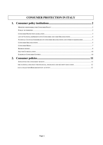
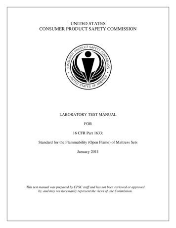
Laboratory Manual: 16 CFR Part 1633 Standard for the Flammability (Open Flame) of Mattress Sets9. CALIBRATION OF TEST INSTRUMENTS9.1 Calorimetry HoodEquipment List:o Propane (or other calibration gas of known heat of combustion)o Sand diffusion burnerProcedure:Perform the calibration of the calorimetry system using common fire laboratory practices with at leasttwo heat release rate (HRR) calibration points, 75 and 200 kW. The frequency of calibration andnumber of points used to calibrate should be determined by the stability of the calorimetry system. It isrecommended that these data be maintained in order to track performance of the calorimetry system overtime. See Appendix I: Practice for Calorimetry Hood Calibration and Validation for a recommendedcalibration procedure.9.2 Propane Flow Control SystemCheck the gas flow rate of each burner at the beginning of each test series. The gas flow rates of eachburner are listed in Table 2.Table 2: Burner Gas Flow RatesFlow Rate (L/min)Burner (L/min)Top12.90.1Side6.60.05Values are based on Standard Atmospheric Pressure (101 5 kilopascals (kPa)) at a temperature of 22 3 degrees Celsius ( C).Equipment List:o Burner assemblyo Connecting hoseo Diaphragm-type test metero Instrumentation for measuring temperature, humidity, and atmospheric pressureo Propane flow control systemo Propane, CPo Stop watchProcedure:1. Refer to Figure 1. Install the diaphragm-type test meter (DTM) downstream of the propane flowcontrol system in the line of the burner to be measured by connecting the hose from the input ofthe DTM to the connector on the control box for the burner to be tested (1) and connecting the7
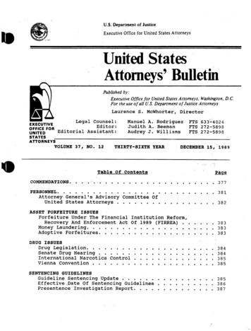
Laboratory Manual: 16 CFR Part 1633 Standard for the Flammability (Open Flame) of Mattress Setsburner hose to the DTM outlet (2). In the example below, the top burner is evaluated.Figure 1. Installation of the DTM in Line with the Burner Assembly2. Connect the pilot hoses (3,5) and remainingburner hose (4) to the propane flow controlsystem.3. Inspect the burners for build up or blockages thatcould impede gas flow. (See Section 10.4Burner Assembly Inspection.)4. Open the main valve on the propane tank and setthe gas pressure to 20 0.5 psig.5. Plug in the propane flow control system andmake sure that the red emergency stop button ispulled out, thereby engaging the power supply.Open the box and set the timers for the burner tobe calibrated to 9999 seconds (or the maximumrange possible). (See Appendix H: Directionsfor Setting 700-HX Timers.)6. Open the ball valves for both burner pilots.(Fig.2)Figure 2. Step 6 Open the ball valves for bothburner pilots.7. Ignite both pilots.8
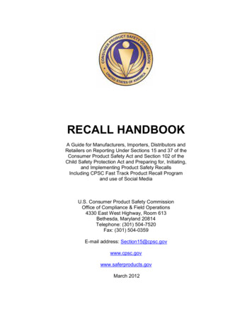
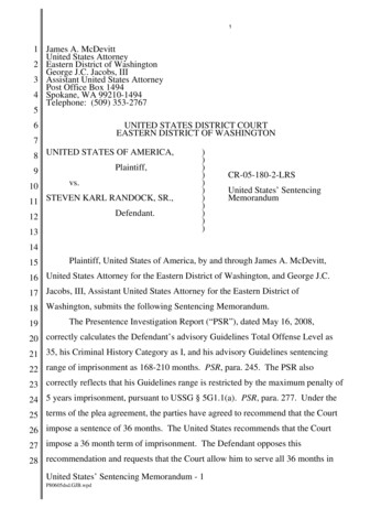
Laboratory Manual: 16 CFR Part 1633 Standard for the Flammability (Open Flame) of Mattress Sets8. Open the ball valves for bothburners.9. Turn both burner switches to“ON” position. (The burnersshould ignite.) (Fig.3)10. Allow the gas to flow for twoto three minutes until theburners and DTM arestabilized. Check allconnecting points for gasleakage.11. Set the horizontal burner flow.Figure 3. Step 9 Turn burner switches to "ON" position.Maintaining a log of flow settings such as that shown in Appendix D: Sample Log Sheetfor Calibration of Propane Flow Control System is helpful for determining the range offlow settings as well as identifying any changes in the propane flow control system overtime.12. Record the barometric pressure and temperature of the test room.13. Record the pressure andtemperature in the DTM.(Fig.4)14. Use a stopwatch to record thegreater of a complete rotationsor at least one minute ofcomplete rotations whilecounting the number ofrotations. This decision shouldbe based on the capacity of theDTM used.15. Calculate the propane gas flowrate using the recorded time andnumber of rotations (total flowin that time). (See Appendix E:Calculations for the Calibrationof the Propane Flow ControlSystem.)Figure 4. Step 13 Record the pressure and temperature in the DTM.9
Laboratory Manual: 16 CFR Part 1633 Standard for the Flammability (Open Flame) of Mattress Sets16. Use the pressure and temperature readings to convert the flow rate to standard conditions.17. Repeat this measurement for two additional flow settings so as to have settings somewhat aboveand below the value of interest.18. Plot the flow versus meter reading(s), fit a best line (possibly quadratic) through these points tofind the correct meter setting to get the flow rates listed in Table 2.19. When three points have been measured with the first burner, shut off the gas at the propane flowcontrol system and allow the gas remaining in the line to burn off. Connect the DTM in line withthe second burner and repeat the calibration procedure.20. After completion of the calibration procedure, re-set the timers for the top and side burners to 70and 50 seconds, respectively. (See Appendix H: Directions for Setting 700-HX Timers.)Mark the correct flow rate on the instrumentation with tape so that the correct flow ratecan be quickly ascertained and adjusted, if necessary, at the beginning of each test.10
Laboratory Manual: 16 CFR Part 1633 Standard for the Flammability (Open Flame) of Mattress Sets10. TEST PREPARATION10.1 Test Area ConditionsMaintain the test area conditions as listed in Table 3.Table 3. Test Area ConditionsTemperature15 C room temperature 27 C(59 F room temperature 80.6 F) 75%Relative Humidity10.2 Prepare Test Floor AreaEquipment List:o Calcium silicate or fiber cement boardo Cleaning materials, as neededProcedure:1. Clean the floor area under the calorimetry hood. Ensure that the floor is free of large debris, dirt,residue, etc. prior to each test. In addition, the floor must be free of standing water and atambient temperature.2. To aid in test clean up and/or to protect the floor, sheets of calcium silicate or fiber cement boardmay be placed under the center of the calorimetry hood to cover the area under the test frame.Do not use dry wall sheets or similar combustible paper products that may ignite andcontribute heat energy. Aluminum foil should not be used since its high reflectivitymay impact test results.10.3 Camera PlacementEquipment List:o Video camera(s) and/or still camera(s) and tripod(s)o Video lightso Video mediaProcedure:1. Place a video or still camera to obtain a full view of the following:o Ignition side of the specimeno Flame impingement area during ignitiono Test floor so that melt pool fires can be seen11
Laboratory Manual: 16 CFR Part 1633 Standard for the Flammability (Open Flame) of Mattress Sets2. Load video media into camera(s).3. Place video light to illuminate specimen.It is recommended that a second camera be placed to obtain a full view of the nonignition side of the specimen. (See Figure 5.)Figure 5. Recommended Camera Placement for Open Calorimeter Testing12
Laboratory Manual: 16 CFR Part 1633 Standard for the Flammability (Open Flame) of Mattress Sets10.4 Burner Assembly Inspection10.4.1 Prepare burner assemblyEquipment List:o Burner assemblyo Lubricant for burner assemblyo Propane Flow Control Systemo Razor blade or box cutterProcedure:Complete the following beforestarting the alignment procedure:o Check the burner assemblypivot point for the top burnerarm. With the pivot point pinremoved, make sure the pivotpoint is clean and lightlylubricated to allow smooth,free movement. Make surethe setscrew is finger tight, butallows free movement of theburner arm. (Fig.6)Figure 6. Bullet 1 Check for ease of movement at pivot point andburner arm.o Check the burner assemblypivot point for the side burnerarm. Make sure the setscrewfor the pivot point is locked inplace to prevent movementduring the test.o The burner holes of eachburner are manufactured fivedegrees (5 ) out of plane.Make sure that the flame jetsof the two burners pointtoward each other. Thischeck is best accomplished byrunning both burners in adraft-free area and observingthe flames from the front of the Figure 7. Bullet 3 Flame jets toward each other.assembly. (Fig.7)13
Laboratory Manual: 16 CFR Part 1633 Standard for the Flammability (Open Flame) of Mattress Setso Wipe residue from both burners with a clean,dry, lint-free rag or paper towel. Do not usesolvents of any kind. If needed, burn offstubborn residue with a small torch. Be surethat the burner holes are not obstructed. Ifnecessary, clean holes with a piece of barecopper wire. Do not scratch burners or usecleaning utensils that may enlarge burner holes.o Check gas fittings for tightness (especially atthe burner connections; the burners should beconnected tightly to their feed lines, unable toshift or rotate about the tubing connections).o Wipe residue from the stand-off feet with aclean dry, lint-free rag or paper towel. Removestubborn residue with a box cutter or similartool. (Fig.8)o Check the burner stand-off feet for straightnessand perpendicularity between the foot pad andthe support rod.Figure 8. Bullet 6 Clean burner stand-off feet.10.4.2 Burner assembly flow rate and timer confirmationEquipment List:o Burner assemblyo Fire suppressionsystem/apparatuso Propane flow control systemo Stop watch or a watch with a“seconds” handProcedure:1. Charge the hose line to beused for fire suppression withwater.2. Connect a hose from thepropane tank to the propaneflow control systemconnection. (Fig.9)Figure 9. Step 2 Connect propane supply.14
Laboratory Manual: 16 CFR Part 1633 Standard for the Flammability (Open Flame) of Mattress Sets3. Connect the burner assembly hoses to the propane flow control system. (Fig.10)Label hoses andconnectors toincrease testefficiency.4. Turn power on for the controlbox by plugging in thepropane flow control systempower cord and making surethat the red emergency stopbutton is pulled out, therebyengaging the power.5. Set propane pressure to 20psig ( 0.5 psig) using theregulator on the gas supply.Open the valve so that gas issupplied to the propane flowcontrol system.Figure 10. Step 3 Connect hoses to control box.6. Check for gas leakage.7. Set burner timers to 70 and 50seconds for the top and sideburners, respectively. (SeeAppendix H: Directions forSetting 700-HX Timers.)8. Adjust pilot tubes to rest justbehind the front surface of theburners. (Fig.11)9. Turn on gas flow to pilots byopening the ball valves. Ignitepilots.Figure 11. Step 8 Adjust pilot tubes.15
Laboratory Manual: 16 CFR Part 1633 Standard for the Flammability (Open Flame) of Mattress Sets10. Set pilot flow valves to nominal 2 cmflames. (Fig.12)11. Simultaneously ignite the burners and starta stop watch to verify timers are setcorrectly.12. Check the settings of the flowmeters, withboth burners running simultaneously, toassure the values give the requisitepropane gas flow rates for each burner.13. Turn off pilot and burner ball valves.Figure 12. Step 10 Set pilot flow.16
Laboratory Manual: 16 CFR Part 1633 Standard for the Flammability (Open Flame) of Mattress Sets11. SETTING BURNER TIMERSBefore setting burner timers, make sure all pilots and burners are turned off.11.1 For Calibration of Propane Flow Control SystemSet the timer to the maximum time (See Appendix H: Directions for Setting 700-HX Timers).11.2 For TestingSet the timer for the top burner to 70.00 seconds and the side burner to 50.00 seconds (See AppendixH: Directions for Setting 700-HX Timers).12. DATA COLLECTIONHeat release rate (HRR) data from the calorimeter instrumentation should be sampled at least once everysix seconds. It is recommended that data be sampled once every second for increased accuracy.17
Laboratory Manual: 16 CFR Part 1633 Standard for the Flammability (Open Flame) of Mattress Sets13. TEST PROCEDUREBackgroundThis test exposes the surfaces of a mattress and its foundation to gas burner flames of a specifiedintensity. That intensity is intended to be comparable to the level experienced by a mattress whenbedclothes are burning on it. As in all gas burner tests, the exposure intensity requires carefulcontrol of certain factors.o The necessary exposure intensity or heat flux is found only at a specific distance from the burnerhead and that distance depends on the gas flow rate to the burner. Therefore, it is essential toset both the gas flow to each burner and the stand-off distance correctly in order to achieve theproper sample surface exposure.o Similarly, it is essential to keep the burner parallel to the sample surface; otherwise, the heatflux will be too high on one side of the burner feed tube and too low on the other side.o Finally, the burner flames should not be significantly disturbed by laboratory air flowfluctuations or the flame movement this causes will lower the average heat flux to which thesample surfaces are exposed.Attention to these issues will minimize operator-to-operator and lab-to-lab variability.Equipment List:o Burner alignment plateno Burner assemblyo Burner stand-off foot jigo Calibrated spring scale (250 gram capacity)o Data sheetso Duct tapeo Extra frame crosspieceso Fire suppression system/apparatuso Instrumentation for measuring temperature, humidity, and atmospheric pressureo Multipurpose lightero Non-combustible material to be used as filler (ex. aluminum foil)o Non-combustible material to be used as risers for test frame (ex. ceramic tile or brick)o Placardo Propane flow control systemo Propane, CPo Razor blade or box cuttero Ruler or other appropriate distance measurement deviceo Scraperso Side burner screeno Stop watch or a watch with a “seconds” hando Test frameo Thermal imaging deviceo Top burner screenso Video camera(s) and/or still camera(s) and tripodso Video lightso Video media18
Laboratory Manual: 16 CFR Part 1633 Standard for the Flammability (Open Flame) of Mattress SetsProcedure:1. Place the test frame in the test area according to the test configuration being used. See§1633.7(2) for more information on the test configurations.2. Check the test frame for residual combustible material. If present, remove material withscrapers.3. Note the time that the specimen is removed from the conditioning room so that the 20 minutemaximum time out of the conditioned environment is not exceeded.4. Center the specimen on the test frame. When centering the specimen keep in mind thefollowing:a. If the mattress is narrower or wider than the foundation, shift the mattress so that the sideto be exposed to the burners is in the same plane as the foundation. If the mattressspecimen is a slightly different dimension than the foundation specimen, note themeasurement difference (cm/in) on the test report.b. If there are unique construction features (e.g., handles, zippers, etc.), place the testspecimen on the frame so the side with the unique construction features is exposed to theburners. (See Section 16. SPECIMEN PLACEMENT: TRADITIONAL AND NONTRADITIONALPRODUCTS.)c. If the specimen is adifferent size or shapethan the test frame,modifications shouldbe made to the frameto accommodate thespecimen. If there areopen spaces betweenthe specimen and thetest frame, use extracross pieces or noncombustible fillers tocover spaces at cornersand along sides of testframe (see AppendixG: Test Frame DesignFigure 13. Step 4.c Close open spaces between the test frame andspecimen.Considerations).(Fig.13)5. Inspect the specimen for defects and note any findings. Remove any tags or labels on thespecimen carefully so that the specimen is not damaged.6. Place video cameras according to instructions. (See Section 10.3 Camera Placement.)7. Place the burner assembly adjacent to the test specimen.19
Laboratory Manual: 16 CFR Part 1633 Standard for the Flammability (Open Flame) of Mattress Sets8. Place the appropriate platen within 30 cm (1 ft) of the longitudinal center of the side of themattress with the shorter side on top.The intended location of the stand-off foot of the top burner is not to be in a dimpleor crease caused by the quilting of the mattress top. If a “construction feature”such as a handle or seam is within 1 ft of the longitudinal center of the mattress, theburner should be aligned with this feature.9. Carefully slide the platen laterally inward from the edge of the mattress so that its side makescontact with either:a. the top and bottom edge of the mattress.b. the vertical side of the mattress.10. Secure the platen using a stripof duct tape to assure that itstays tightly in place against theside of the mattress. (Fig.14)Figure 14. Step 10 Secure the platen.20
Laboratory Manual: 16 CFR Part 1633 Standard for the Flammability (Open Flame) of Mattress Sets11. Place the burner assemblyadjacent to the test specimenwith both burner arms secured(pivot point pinned in position),with stand-off feet of bothburners fully retracted. Makesure that the pilot tubes do notextend beyond the burner headfaces to prevent damage to thepilot tubes. (Fig.15)Figure 15. Step 11 Check pilot tube.12.
Figure 1. Installation of the DTM in Line with the Burner Assembly 2. Connect the pilot hoses (3,5) and remaining burner hose (4) to the propane flow control system. 3. Inspect the burners for build up or blockages that could impede gas flow. (See Section 10.4 Burner Assembly Inspection.) 4. Open the main valve on the propane tank and set