Transcription
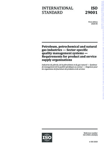
certified QualitysystemISO 9001 / EN 29001Reg. Nr. 10529MMI 810.1 / 811.1A Honeywell CompanyGas burner automaticsafety controlFor 2-stage forced draught and combi oil/gas burnersPossible flame detectors:- Ionization probe- Infrared flicker detectorINTRODUCTIONThe gas burner automatic safety control MMI controlsand monitors blown gas- and combined burners of anynominal thermal load (tested and certified according toEN 298).The automatic safety controls MMI 810.1 models 13, 33 and35 can also be utilized for burners on fixed hot air heaters(Direct air heaters according to DIN 4794).Various types and model designations differentiate theautomatic safety controls with respect to the programmetimes, as well as with regard to differing national standards.TECHNICAL DATAOperating voltageDiffering frequencyRating fusePower consumptionMax. load per output:- term. 3- term. 4, B- term. 5, 6total loadAmplifier sensitivityMinimum requiredIonization currentFlame detector cableAir pressure monitorWaiting time formalfunction remedyFlame detector- Ionization probe- Infrared flicker detectorWeight, incl. baseMounting positionInsulation standardAdmissible ambienttemperature for controllerand flame detectorClassified acc. to EN 298TYPES AVAILABLEMMI 810.1MMI 811.1Mod. 13 *Mod. 33Mod. 35Mod. 43Mod. 55Mod. 35Mod. 63Art. Nr. 0620720Art. Nr. 0620220Art. Nr. 0620920Art. Nr. 0622520Art. Nr. 0621320Art. Nr. 0621120Art. Nr. 0620420* Must only be used on boilers or other applications wherethe 10 second pre-purge time is sufficient to provide atleast 3 volume changes of the combustion chamber.CONSTRUCTIONAL FEATURESThe automatic control is housed in a non-inflammable,transparent, plug-in type plastic case and contains:– Synchronous motor with speed reducer gears as thedrive for the switching cam– Switching cam with informative programme display incolour– 12 times cam drive for controlling the programmesequence– Plug-in type circuit boards with the electronic components0708.21-01-e/04/99220 / 240 V (-15. 10%)50 Hz (50 - 60 Hz)Results in a proportionaldeviation of the time.max. 10 A rapid, 6 A slow10 VA2A, cos ϕ 0.22A, cos ϕ 0.41A, cos ϕ 0.45A, cos ϕ 0.41 µA5 µAmax. 20 m cable lengthworking contact 4 A, 230 VNoneIRD 1020350 ganyIP 44-20 C 60 CBTLLXNprogramMMI 810.1811.1timings (sec.)ModellWaiting timeat start ca.Max. reactiontime for airproving switchPre-purge timePre-ignitiontimeT. ignition timeSafety timeTime delayterm.6/term.CThe following important indicating - and operating elementsare located on the front panel of the automatic control:– Illuminated pushbutton for indication of malfunctionsand reset– Programme display in colour– Screw for central mounting133335435535636999996tlw 3.5tv1 53tv2610101010106twFor external resetting, the remote reset device FR 870(art. No. 70700) can be utilized. (Refer to doc. 750).1
APPLICATION TECHNOLOGY FEATURESCOMMISSIONING AND SERVICE/MAINTENANCE1. Flame MonitoringThe flame monitoring can be effected with the followingflame detectors:- With ionization electrodes in power grids with earthedneutral conductor, utilizable with gas burners (interferenceeffects of the ignition spark cannot influence the formationof the flame signal).- With infrared flicker detector type IRD 1020 for all typesof burners.1. Important Remarks– Before commissioning, the wiring has to be accuratelychecked. Faulty wiring can damage the unit and endangerthe safety of the installation.– The mains fuse has to be selected so that the limit valuesindicated under "Technical Specifications" are under nocircumstances exceeded. Non-compliance with thisregulation can have very serious consequences for thecontrol unit and for the installation in the case of a shortcircuit.– For safety reasons, at least one control shut-down per 24hours must be assured.– The control unit must be plugged-in or -out only when themains supply has been disconnected.– Automatic burner safety controls are safety devices andmust not be opened.2. Burner Control– The burner controls features a low-voltage protection. Ifthe supply voltage dropps below 160 V during operation,the burner switches-off. When the supply voltage raisesabove 180 V, the burner performs a restart independently.– The automatic burner controls MMI only operate, when aload is connected to terminal 5. If the fuel valve isinterrupted by an external contact during the pre-purgingphase, a resistance of max. 22 kW, 4 Watt has to beapplied bet-ween the terminals 5 and 8.– Functional test of the air pressure monitor before thestartup and monitoring of the air pressure during the prepurging time, as well as in the operating condition of theburner. For normal applications a working contact with apower rating of 4 A / 230 V is sufficient.– In the case of the automatic control MMI 810.1, contactscan be installed between the terminals 1 and 9 (e.g., valvelimit position contacts). These are checked for theircorrect closing position when the unit is started up. Theconnection 1 - 9 has to be closed during the startingphase of the automatic control.2. Functional CheckDuring commissioning and after an overhaul of the burner,the following checks have to be carried out:a) Starting test with closed manual valve and bridged gasmonitor contact:– The device must go into a fault condition after thesafety period has elapsed.b) Close the manual valve in operating position with the gasmonitor contact bridged.– The device must go into a fault condition after a flamefailure.c) Air pressure monitor contact interrupted:– Device goes into a fault condition.d) Bridge air pressure monitor contact before starting:– Device must not start.3. SafetyWith respect to design and programme sequence, the gasburner automatic safety controls of the MMI type rangecomply with the currently applicable European standardsand regulations.3. Trouble ShootingBurner does not go into operation, programme indicationremains:– Electrical connection defective.– Thermostat or gas monitor "OFF".4. Mounting and Electrical InstallationOn the base:– 3 earth conductor terminals with additional strap for theearthing of the burner.– 3 neutral conductor terminals with an internal, fixedconnection to the neutral conductor input, terminal 8.– 2 individual slide-in plates and 2 fixed knock-out apertureswith thread PG 11, as well as 2 knock-out apertures frombelow, make the wiring of the base more easy.Burner does not go into operation, programme indicationrotates continuously:– Air pressure monitor defective, respectively, not in startingposition. (Working contact must be open).– Connection term. 1 - term. 9 interrupted– mains voltage 180VThe automatic control switches to fault condition shortlyafter the start of the pre-purge time (line within the bluezone):– Air pressure monitor contact does not close.– No load on terminal 5.– Flame signal.General:– Mounting position as required, insulation standard IP 44(splash-proof). The automatic control and sensor should,however, not be exposed to excessive vibration.– During mounting and installation, the applicable regulations for installation have to be observed.Automatic control switches to fault condition during theoperating position (red, resp. green zone):– Flame lift-off– Air pressure monitor contact opens– Flame signal too weak.2MMI 810.1 / 811.1Automatic control switches to fault condition during the prepurging (blue zone):– No flame formation (ignition missing, valve does notopen, etc.)– No flame signal or too weak flame signal (flame does notadhere, poor insulation of the flame detector, burner notproperly connected to the earth conductor).
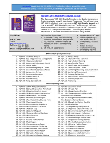
SCHEMATIC CONNECTION DIAGRAM AND PROCESS DIAGRAM MMI 810.1max. 10 A rapid6 A slowPh12A/3HS4STGW56BRT789CLWISZMV1SAV2Ntw tlw tv1 tvz tzts tv2SCHEMATIC CONNECTION DIAGRAM AND PROCESS DIAGRAM MMI 811.1STPh max. 10 A rapid6 A slow12HSA/34RTSV56B789GWCMZV1V2Main switchGas pressure switchLimit thermostatControl thermostatIonization probeIgnitionBurner motorSolenoid valve 1st stageSolenoid valve 2nd stageAir pressure monitorExternal fault indicationSafety valvetwtlwWaiting time at start-upMax. reaction timefor air proving switchPre-purge timePre-ignition timeTotal ignition timeSafety timeTime delay term.6 / term.Ctv1tvztztstv2LWISHSGWSTRTISZMV1V2LWSASVSANtw tlw tv1 tvz tzts tv2IRD CONNECTIONIRD1020blueterm. 8blackterm. 2brownterm. 9SCHEMATIC DIAGRAM MMI 811.1MMI 810.1 / 811.1SCHEMATIC DIAGRAM MMI 810.13
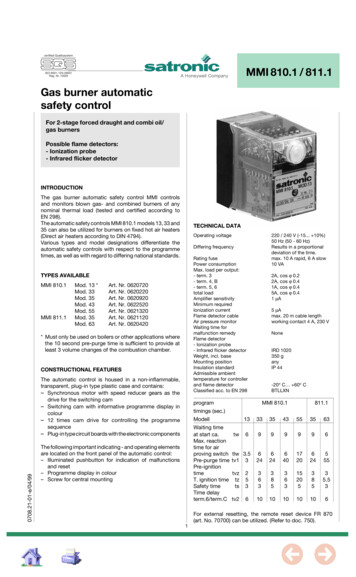
MMI WITH BASEMEASUREMENT OF THE FLAME SIGNAL52MMI 810.1 / MMI 811.167E91PG 11 24The signal shouldbe greater than 5 µASlide-in plate241630Earth0 - 10 µA0 - 100 µAThe Satronic Ionimeteris ideal for makingthis measurement.30M43057-60ø 16 mm,cable entry from belowHOLDER M93IRD 10203ø13.521.835445029144.5263544Reset button2516-618710415.117 448ø20.5ORDERING INFORMATIONITEMDESIGNATIONITEM NO.Control unitorBase for MMI 810.1Base for MMI 811.1Slide-in plateoptionallyFlame detectorFlame detectorFlame detectorIRD mounting flangeFlame detector cableType MMI 810.1 mod. 33Type MMI 811.1 mod. 35Base 701 TTG-ENBase 710 TTG-FNPG-plateCable clamping plateIRD 1020 end-on viewingIRD 1020 side-on leftIRD 1020 side-on rightIRD Holder M933-wire, 0.6 590937236001The above ordering information refers to the standard version.Special versions are also included in our product range.MMI 810.1 / 811.1Specifications subject to change without notice.A Honeywell Company4Satronic AGBrüelstrasse 7Postfach 324CH-8157 Dielsdorf
certified Qualitysystem515e/08/96ISO 9001 / EN 29001Reg. Nr. 10529A Honeywell CompanyMMI 812Gas burner automaticsafety controlFor 2-stage forced draught gas burnersFacility to connect an air damper unitPossible flame detectors:- Ionization probe- Infrared flicker detectorINTRODUCTIONThe gas burner automatic safety control MMI 812 controlsand monitors blown gas- and combined burners of anynominal thermal load (tested and certified according toEN 298).If an air damper unit is connected, a 2-stage operation withtwo fuel valves or a modulating operation with one fuel valveis possible.Various types and model designations differentiate theautomatic safety controls with respect to the programmetimes, as well as with regard to differing national standards.TECHNICAL DATAOperating voltageDiffering frequencyRating fusePower consumptionMax. load per outputOverallAmplifier sensitivityMinimum requiredIonization currentFlame detector cableAir pressure monitorWaiting time formalfunction remedyFlame detector- Ionization probe- Infrared flicker detectorWeight, incl. baseMounting positionInsulation standardAdmissible ambienttemperature for controllerand flame detectorClassified acc. to EN 298TYPES AVAILABLEMMI 812.1MMI 812Modell 23Modell 33Art. Nr. 06223Art. Nr. 06205CONSTRUCTIONAL FEATURESThe automatic control is housed in a non-inflammable,transparent, plug-in type plastic case and contains:- Synchronous motor with speed reducer gears as the drivefor the switching cam- Switching cam with informative programme display incolour- 10 times cam drive for controlling the programme sequence- Plug-in type circuit boards with the electronic componentsThe following important indicating - and operating elementsare located on the front panel of the automatic control:- Illuminated pushbutton for indication of malfunctions andreset- Programme display in colour- Screw for central mounting220 / 240 V (-15. 10%)50 Hz (40 - 60 Hz)Results in a proportionaldeviation of the time.max. 10 A rapid, 6 A slow10 VA4A6A1 µA5 µAmax. 20 m cable length1 working contact 4 A, 230 VNoneIRD 1020350 gAnyIP 44-20 C. 60 CBTLLXNprogram timings (sec.)MMI 812.1MMI .536ModellWaiting time at start-upMax. reaction time for airproving switchPre-purge timeLK open signalPre-ignition timeTotal ignition timeSafety timeTime delay term.6 / term.CFor external resetting, the remote reset device FR 870(art. No. 70700) can be utilized. (Refer to doc. 750).1
APPLICATION TECHNOLOGY FEATURESCOMMISSIONING AND SERVICE/MAINTENANCE1. Flame Monitoring1. Important RemarksThe flame monitoring can be effected with the followingflame detectors:- With ionization electrodes in power grids with earthedneutral conductor, utilizable with gas burners (interferenceeffects of the ignition spark cannot influence the formationof the flame signal).- With infrared flicker detector type IRD 1020 for all typesof burners.- Before commissioning, the wiring has to be accuratelychecked. Faulty wiring can damage the unit and endangerthe safety of the installation.- The mains fuse has to be selected so that the limit valuesindicated under "Technical Specifications" are under nocircumstances exceeded. Non-compliance with thisregulation can have very serious consequences for thecontrol unit and for the installation in the case of a shortcircuit.- For safety reasons, at least one control shut-down per 24hours must be assured.- The control unit must be plugged-in or -out only when themains supply has been disconnected.- Automatic burner safety controls are safety devices andmust not be opened.2. Burner Control- The automatic burner controls MMI only operate, when aload is connected to terminal 5. If the fuel valve is interruptedby an external contact during the pre-purging phase, aresistance of max. 22 kΩ, 4 Watt has to be applied between the terminals 5 and 8.- Functional test of the air pressure monitor before thestartup and monitoring of the air pressure during the prepurging time, as well as in the operating condition of theburner. For normal applications a working contact with apower rating of 4 A / 230 V is sufficient.- In the case of the automatic control MMI 810, contacts canbe installed between the terminals 1 and 9 (e.g., valve limitposition contacts). These are checked for their correctclosing position when the unit is started up. The connection1 - 9 has to be closed during the starting phase of theautomatic control.- No fuel valve must be connected to terminal 6.2. Functional CheckDuring commissioning and after an overhaul of the burner,the following checks have to be carried out:a) Starting test with closed manual valve and bridged gasmonitor contact:-The device must go into a fault condition after the safetyperiod has elapsed.b) Close the manual valve in operating position with the gasmonitor contact bridged.-The device must go into a fault condition after a flamefailure.c) Air pressure monitor contact interrupted:-Device goes into a fault condition.d) Bridge air pressure monitor contact before starting:-Device must not start.3. SafetyWith respect to design and programme sequence, the gasburner automatic safety controls of the MMI type rangecomply with the currently applicable European standardsand regulations.3. Trouble ShootingBurner does not go into operation, programme indicationremains:- Electrical connection defective.- Thermostat or gas monitor "OFF".4. Mounting and Electrical InstallationOn the base:- 3 earth conductor terminals with additional strap for theearthing of the burner.- 3 neutral conductor terminals with an internal, fixedconnection to the neutral conductor input, terminal 8.- 2 individual slide-in plates and 2 fixed knock-out apertureswith thread PG 11, as well as 2 knock-out apertures frombelow, make the wiring of the base more easy.Burner does not go into operation, programme indicationrotates continuously:- Air pressure monitor defective, respectively, not in startingposition. (Working contact must be open).The automatic control switches to fault condition shortlyafter the start of the pre-purge time (line within the bluezone):- Air pressure monitor contact does not close.- No load on terminal 5.- Flame signal.General:- Mounting position as required, insulation standard IP 44(splash-proof). The automatic control and sensor should,however, not be exposed to excessive vibration.- During mounting and installation, the applicable regulations for installation have to be observed.Automatic control switches to fault condition during theoperating position (red, resp. green zone):- Flame lift-off- Air pressure monitor contact opens- Flame signal too weak.2MMI 812Automatic control switches to fault condition during the prepurging (blue zone):- No flame formation (ignition missing, valve does not open,etc.)- No flame signal or too weak flame signal (flame does notadhere, poor insulation of the flame detector, burner notproperly connected to the earth conductor).
SCHEMATIC CONNECTION DIAGRAM AND PROCESS DIAGRAM MMI 812PhGWHSmax. 10 A rapid6 A slowSTRTHSGWSTRTISZMV1LLWSAMain switchGas pressure switchLimit thermostatControl thermostatIonization probeIgnitionBurner motorSolenoid valve 1st stageAir damper unitAir pressure monitorExternal fault indicationNtwtlwMMI 812tv1tlktvztztstv2Waiting time at start-upMax. reaction timefor air proving switchPre-purge timeLK open signalPre-ignition timeTotal ignition timeSafety timeTime delay term.6 / term.C12A/3456CB789LWISZMV1LSAtw tlw tv1 tlk tvz tz ts tv2IRD CONNECTIONIRD1020blueKl. 8blackKl. 2brownKl. 9SCHEMATIC DIAGRAM MMI 812MMI 812RF3
MMI WITH BASEMEASUREMENT OF THE FLAME SIGNAL52MMI 81267E91PG 11 24The signal shouldbe greater than 5 µASlide-in plate241630Earth0 - 10 µA0 - 100 µAThe Satronic Ionimeteris ideal for makingthis measurement.30M43057-60ø 16 mm,cable entry from belowHOLDER M93IRD 10203ø13.521.835445029144.5263544Reset button2516-618710415.117 448ø20.5ORDERING INFORMATIONITEMDESIGNATIONITEM NO.Control unitorBase for MMI 811Slide-in plateoptionallyFlame detectorFlame detectorFlame detectorIRD mounting flangeFlame detector cableType MMI 812.1 mod. 23Type MMI 812 mod. 33Base 710 TTG-FNPG-plateCable clamping plateIRD 1020 end-on viewingIRD 1020 side-on leftIRD 1020 side-on rightIRD Holder M933-wire, 0.6 001The above ordering information refers to the standard version.Special versions are also included in our product range.MMI 812Specifications subject to change without notice.A Honeywell Company4Satronic AGBrüelstrasse 7Postfach 324CH-8157 Dielsdorf
certified QualitysystemISO 9001 / EN 29001Reg. Nr. 10529A Honeywell CompanyMMI 813.1Gas burner automaticsafety controlFor 2-stage forced draught gas burnersDesignated for an air damper controlPossible flame detectors:- Ionization probe- Infrared flicker detectorINTRODUCTIONThe gas burner automatic safety control MMI 813.1 controlsand monitors blown gas- and combined burners of anynominal thermal load (tested and certified according toEN 298).Together with an air damper motor, a 2-stage burner with2 fuel valves, a 2-stage operation with 1 fuel valve or amodulating system ave possible.TECHNICAL DATAOperating voltageDiffering frequencyRating fusePower consumptionMax. current per outputterm. 3term. 4, Bterm. 5, 6, CTotal loadAmplifier sensitivityMinimum requiredIonization currentFlame detector cableAir pressure monitorWaiting time formalfunction remedyRunning timeair damper for 90 Flame detector- Ionization probe- Infrared flicker detectorWeight, incl. baseMounting positionInsulation standardAdmissible ambienttemperature for controllerand flame detectorClassification acc. EN 298CONSTRUCTIONAL FEATURESThe automatic control is housed in a non-inflammable,transparent, plug-in type plastic case and contains:– Synchronous motor with speed reducer gears as thedrive for the switching cam– Switching cam with informative programme display incolour– 12 times cam drive for controlling the programmesequence– Plug-in type circuit boards with the electronic componentsThe following important indicating - and operating elementsare located on the front panel of the automatic control:– Illuminated pushbutton for indication of malfunctionsand reset– Programme display in colour– Screw for central mounting0708.24-01-e/04/99Automatic Control220 / 240 V (-15. 10%)50 Hz (50 - 60 Hz)results in a proportionaldeviation of the time.max. 10 A rapid, 6 A slow10 VA2A, cos ϕ 0.22A, cos ϕ 0.41A, cos ϕ 0.45A, cos ϕ 0.41 µA5 µAmax. 20 m cable length1 working contact 4 A, 220 Vnonemax. 15 sec.IRD 1020350 ganyIP 44-20 C. 60 CBTLLXNMMI 813.1Model23Waiting time at start approx. twMaximum reaction timeof air pressure monitortlwPre-purge timetv1Air damper open signalduring pre-purgetlkPre-ignition timetvzIgnition time, overalltzIgnition safety timetsDelay time terminal 6tv29103436.53636For external resetting, the remote reset device FR 870(art. No. 70700) can be utilized. (Refer to documentation750).1
APPLICATION TECHNOLOGY FEATURESCOMMISSIONING AND SERVICE/MAINTENANCE1. Flame MonitoringThe flame monitoring can be effected with the followingflame detectors:– With ionization electrodes in power grids with earthedneutral conductor, utilizable with gas burners (interferenceeffects of the ignition spark cannot influence the formationof the flame signal).– With infrared flicker detector type IRD 1020 for all typesof burners.1. Important Remarks– Before commissioning, the wiring has to be accuratelychecked. Faulty wiring can damage the unit and endangerthe safety of the installation.– The mains fuse has to be selected so that the limit valuesindicated under "Technical Specifications" are under nocircumstances exceeded. Non-compliance with thisregulation can have very serious consequences for thecontrol unit and for the installation in the case of a shortcircuit.– For safety reasons, at least one control shut-down per24 hours must be assured.– The control unit must be plugged-in or -out only when themains supply has been disconnected.– Automatic burner safety controls are safety devices andmust not be opened.2. Burner Control– The burner controls features a low-voltage protection. Ifthe supply voltage dropps below 160 V during operation,the burner switches-off. When the supply voltage raisesabove 180 V, the burner performs a restart independently.– The automatic burner controls MMI only operate, when aload is connected to terminal 5. If the fuel valve isinterrupted by an external contact during the pre-purgingphase, a resistance of max. 22 kW, 4 Watt has to beapplied bet-ween the terminals 5 and 8.– Functional test of the air pressure monitor before thestartup and monitoring of the air pressure during the prepurging time, as well as in the operating condition of theburner. For normal applications a working contact with apower rating of 4 A / 220 V is sufficient.– In the case of the automatic control MMI 813.1, contactscan be installed between the terminals 1 and 9 (e.g., valvelimit position contacts). These are checked for theircorrect closing position when the unit is started up. Theconnection 1-9 has to be closed during the startingphase of the automatic control.2. Functional CheckDuring commissioning and after an overhaul of the burner,the following checks have to be carried out:a) Starting test with closed manual valve and bridged gasmonitor contact:– The device must go into a fault condition after thesafety period has elapsed.b) Close the manual valve in operating position with the gasmonitor contact bridged.– The device must go into a fault condition after a flamefailure.c) Air pressure monitor contact interrupted:– Device goes into a fault condition.d) Bridge air pressure monitor contact before starting:– Device must not start.3. Trouble ShootingBurner does not go into operation, programme indicationremains:– Electrical connection defective– Thermostat or gas monitor "OFF"3. SafetyWith respect to design and programme sequence, the gasburner automatic safety controls of the MMI type rangecomply with the currently applicable European standardsand regulations.Burner does not go into operation, programme indicationrotates continuously:– Air pressure monitor defective, respectively, not in startingposition. (Working contact must be open).– Connection term. 1 - term. 9 interrupted– mains voltage 180V4. Mounting and Electrical InstallationWiring base:– 3 earth terminals with additional terminal for burnerearthing– 3 neutral terminals with internal permanent connection toneutral terminal 8– 2 independant spare terminals (S1 and S2)– extra terminals A, B and C are standard– 2 slide-in plates and 2 easy knock out holes (PG11thread) plus 2 knock out holes in the base bottom faciliatethe base wiringThe automatic control switches to fault condition shortlyafter the start of the pre-purge time (line within the bluezone):– Air pressure monitor contact does not close– No load on terminal 5– Flame signalGeneral:– Mounting position as required, insulation standard IP 44(splash-proof). The automatic control and sensor should,however, not be exposed to excessive vibration.– During mounting and installation, the applicable regulations for installation have to be observed.Automatic control switches to fault condition during the prepurge (blue zone):– Air pressure monitor contact open– Flame signal (stray light)Automatic control switches to fault condition during theoperating position (red, resp. green zone):– Flame lift-off– Air pressure monitor contact opens– Flame signal too weak.2MMI 813.1Automatic control switches to fault condition during thesafety time (yellow zone):– No flame formation (ignition missing, valve does notopen, etc.)– No flame signal or too weak flame signal (flame does notadhere, poor insulation of the flame detector, burner notproperly connected to the earth conductor).
SCHEMATIC CONNECTION DIAGRAM AND PROCESS DIAGRAM MMI 813.1WITH AIR DAMPER CONTROLPh12A/3GWHSmax. 10 A rapid6 A wSAWITHOUT AIR DAMPER CONTROLPhHSmax. 10 A rapid6 A slow12A/34GW5ST6CRTB789tvztztstv2LWISZMV1V2SANtw tlw tv1 tlk tvz tz ts tv2IRD CONNECTIONIRD1020tv1tlkblueterm. 8blackterm. 2brownterm. 9MMI 813.1SCHEMATIC DIAGRAM MMI 813.13Main switchGas pressure switchLimit thermostatControl thermostatIonization probeIgnitionBurner motorSolenoid valve 1st stageSolenoid valve 2nd stageAir damper control unitAir pressure monitorExternal fault indicationWaiting time at start-upmax. reaction timeof air pressure monitorPre-purge periodAir damper open signalduring pre-purgePre-ignition periodOverall ignition periodSafety periodTime delay terminal 6
MMI WITH BASEMEASUREMENT OF THE FLAME SIGNAL5E267MMI 813.191PG 11 24The signal shouldbe greater than 5 µA-87Slide-in plate2430The Satronic Ionimeteris ideal for makingthis measurement.Earth1630M43057-60ø 16 mm,cable entry from belowHOLDER M93IRD 10203ø13.521.829354450144.52625163544Reset button0 - 10 µA0 - 100 µA10415.117 448ø20.5ORDERING INFORMATIONITEMDESIGNATIONITEM NO.Control unitBase for MMI 813.1 (without air damper)Base for MMI 813.1 (with air damper)Slide-in plateoptionallyFlame detectorFlame detectorFlame detectorIRD mounting flangeFlame detector cableType MMI 813.1 mod. 23Wiring base 701 TTG-ENWiring base S 98PG-plateCable clamping plateIRD 1020 end-on viewingIRD 1020 side-on leftIRD 1020 side-on rightIRD Holder M933-wire, 0.6 36001The above ordering information refers to the standard version.Special versions are also included in our product range.MMI 813.1Specifications subject to change without notice.A Honeywell Company4Satronic AGBrüelstrasse 7Postfach 324CH-8157 Dielsdorf
certified Qualitysystem512/04/94ISO 9001 / EN 29001Reg. Nr. 10529A Honeywell CompanyMMI 815GasfeuerungsautomatFür atmosphärische Gasbrennerbis max. 350 kW Nennleistung 2-stufigMögliche Flammenfühler:- Ionisationssonde- Infrarot-FlackerdetektorANWENDUNGSBEREICHDer Gasfeuerungsautomat MMI 815 steuert und überwachtatmosphärische Gasbrenner.AUFBAU UND KONSTRUKTIONTECHNISCHE DATENDie Automatik ist gut geschützt in einem schwer entflammbaren, transparenten und steckbaren Kunststoffgehäuseeingebaut und beinhaltet:- Synchronmotor mit Untersetzungsgetriebe als Schaltwalzenantrieb- Schaltwalze mit informativer, farbiger Programmanzeige- 10-fach Nockenschaltwerk zur Steuerung des Programmablaufs- Steckbare Printplatten mit den elektronischen KomponentenBetriebsspannungAbweichende FrequenzVorsicherungEigenverbrauchMax. Belastung pro AusgangTotalEmpfindlichkeit VerstärkerMin. erforderlicherIonisationsstromLeitung FlammenfühlerWartezeit für EntstörungFlammenfühler- Ionisationssonde- Infrarot-FlackerdetektorGewicht inkl. SockelEinbaulageSchutzartZugelassene Umgebungstemperatur fürGerät und FlammenfühlerFolgende wichtige Anzeige- und Bedienungselemente sindauf der Frontseite des Automaten zusammengefasst:- Leuchttaste für Störanzeige und Entriegelung- Farbige Programmanzeige- Schraube zur Zentralbefestigung220 / 240 V (-15. 10%)50 Hz (40 - 60 Hz)ergibt proportionaleAbweichung der Zeitmax. 10 A flink, 6 A träge10 VA4A6A1 µA5 µAmax. 20 m KabellängekeineIRD 1020350 gbeliebigIP 44-20 C 60 CAutomatMMI 815ModellWartezeit Start ca.5171017VorspülzeitVorzündzeit44Zündzeit totalSicherheitszeit8513 9Verzög. 2. Stufe1515Zur externen Entriegelung kann die Fernrückstellung FR870 (Art. Nr.70700) eingesetzt werden.1
ANWENDUNGSTECHNISCHE MERKMALEINBETRIEBNAHME UND UNTERHALT1. Flammenüberwachung1. Wichtige HinweiseDie Flammenüberwachung kann mit folgenden Flammenfühlern erfolgen:- Mit Ionisationselektrode in Netzen mit geerdetem Nullleiter, anwendbar bei Gasbrennern (Störeinflüsse desZündfunkens können die Bildung des Flammensignalsnicht beeinflussen)- Mit Infrarot-Flackerdetektor Typ IRD 1020 für alle Brennerarten- Vor Inbetriebnahme ist die Verdrahtung genau nachzuprüfen. Fehlverdrahtungen können das Gerät beschädigen und die Sicherheit der Anlage gefährden.- Die Vorsicherung ist so zu wählen, dass die unter denTechnischen Daten angegebenen Grenzwerte keinesfallsüberschritten werden.- Das Nichtbeachten dieser Vorschrift kann bei einemKurzschluss schwerwiegende Folgen für Steuergerät oderAnlage haben.- Aus sicherheitstechnischen Gründen muss mindestenseine Regelabschaltung pro 24 Std. sichergestellt sein.- Steuergerät nur spannungslos ein- und ausstecken.- Feuerungsautomaten sind Sicherheitsgeräte und d
A Honeywell Company certified Qualitysystem ISO 9001 / EN 29001 Reg. Nr. 10529 MMI 810.1 / 811.1 Gas burner automatic safety control For 2-stage forced draught and combi oil/ gas burners Possible flame detectors: - Ionization probe - Infrared flicker detector INTRODUCTION The gas burner automatic safety control MMI controls