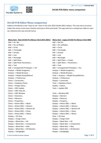
Transcription
Creating a schematic circuitOrCAD Capture CISCreating a circuit with OrCAD Capture CISIn this part of the workshop you will be creating the schematic for a lowpass filter including theparts necessary for simulating the circuit with PSpice.Table of ContentsCreating a circuit with OrCAD Capture CIS . 1Schematic Capture . 1Placing Parts from the component database . 3Placing parts using PSpice Search . 5Placing sources for PSpice simulation . 7Placing power and ground symbols . 8What did you learn? . 9Component databases . 10Keyboard shortcuts . 11Schematic CaptureThe final schematic design is shown below.1. Be sure to start OrCAD Capture with the CIS option Nordcad Systems A/S /Nordcad AS 2018 - R2support@nordcad.dk / support@nordcad.no 45 96 31 56 99 / 47 21 55 28 28Page 1 of 11
Creating a schematic circuitOrCAD Capture CIS2. At startup the Start Page will be shown. If not select Help Start Page.3. On the Start page select New Project.or4. When you create the new project specify a name. In this case name the project “Lowpassfilter” as shown.a. Make sure to select “PSpice Analog or Mixed A/D” project in order to get all thePSpice functionality. Nordcad Systems A/S /Nordcad AS 2018 - R2support@nordcad.dk / support@nordcad.no 45 96 31 56 99 / 47 21 55 28 28Page 2 of 11
Creating a schematic circuitOrCAD Capture CISTIP: In case your project type by mistake was set to something else then it is easy to change fromthe project manager using the Change Project Type function shown below.5. Click the create a blank project and then press ok.6. It is often an advantage to be able to see the project manager. Right click the tab named“Lowpass filter” and select Dock to Left7. To find your schematic inside OrCAD Capture, look under your project DSN file.Placing Parts from the component database8. Now start placing parts needed for the Lowpass filter. On the empty schematic page rightclick Place Database Part. (Shortcut key: z) Nordcad Systems A/S /Nordcad AS 2018 - R2support@nordcad.dk / support@nordcad.no 45 96 31 56 99 / 47 21 55 28 28Page 3 of 11
Creating a schematic circuitOrCAD Capture CIS9. A component database is shown in the CIS Explorer. Parts can be found either througha. “Explore” where parts can be identified from the categorization into part typesb. “Query” where parts can be found through parameter search10. Find the part with part number CIS-1 either through the Explore tree“Capacitors Ceramic SMD 0603” or using Query as shown belowCapacitors11. Double click the line (4) above to place the part on the schematic page12. Press ‘z’ again to get back into the CIS Explorer and search for the 15.8k resistor and placethe resistor on the schematic page Nordcad Systems A/S /Nordcad AS 2018 - R2support@nordcad.dk / support@nordcad.no 45 96 31 56 99 / 47 21 55 28 28Page 4 of 11
Creating a schematic circuitOrCAD Capture CISResistors13. Use the same methodology to find and place the resistor with the value of 1mPlacing parts using PSpice Search14. To place the opamp we’re going to search in the built in library of parts with PSpice models.Select Place PSpice Component SearchIC Nordcad Systems A/S /Nordcad AS 2018 - R2support@nordcad.dk / support@nordcad.no 45 96 31 56 99 / 47 21 55 28 28Page 5 of 11
Creating a schematic circuitOrCAD Capture CIS15. Type in ‘TL071’ to search for the opamp16. Double click the line “TL071/301/TI’ above in order to place the componenta. The opamp can be mirrored to have the negative pin on top either by Right Click Mirror Vertically or using shortcut ‘v’17. Now the wiring can begin. The shortcut for placing a wire is “W”2R113215.8K- 7U1TL071/301/TI5N26OUT1N1V V-418. After the wiring is done, the schematic should look something like this.C10.01uFR21m Nordcad Systems A/S /Nordcad AS 2018 - R2support@nordcad.dk / support@nordcad.no 45 96 31 56 99 / 47 21 55 28 28Page 6 of 11
Creating a schematic circuitOrCAD Capture CISPlacing sources for PSpice simulation19. We will place power/ground symbols and sources for PSpice simulation.20. To place a sine source, go to Place PSpice Component Modelling Applications Sources Independent Sources21. Set the parameters for the source as shown below and place it on the page Nordcad Systems A/S /Nordcad AS 2018 - R2support@nordcad.dk / support@nordcad.no 45 96 31 56 99 / 47 21 55 28 28Page 7 of 11
Creating a schematic circuitOrCAD Capture CIS22. To place a DC voltage source use a similar function. Go to Place PSpice Component Modelling Applications Sources Independent Sources23. Select the tab ‘DC’ and set the DC Voltage 5 and place the source24. Copy the DC source that was just placed using ctrl c and ctrl v25. Change the value of the new DC source to -5V by double clicking the valueV25V3-5Placing power and ground symbols26. To place power and ground symbols use Place Power/Ground or shortcut ‘g’27. PSpice simulations always needs a 0 reference and to place this start typing ‘0’ in the Place Power/Ground dialog28. Place 4 x ‘0’ ground symbols29. In the Place power/ground dialog type ‘VCC’ to see the power symbols with names startingwith VCC Nordcad Systems A/S /Nordcad AS 2018 - R2support@nordcad.dk / support@nordcad.no 45 96 31 56 99 / 47 21 55 28 28Page 8 of 11
Creating a schematic circuitOrCAD Capture CIS30. Select VCC and click OK to place it.31. Make 3 copies of the VCC symbol just placed and rename 2 of those to ‘VEE’32. Now finish up the schematic to look like the one belowa. To name the nets ‘in’ and ‘out’ select Place Net Alias or use shortcut ‘n’. Thentype the name of the net and place it on the wire.31 U1C10.01uF215.8K7R1in-TL071/301/TI5N26OUT1N1V 2V-4VEEVCCVCCV1VOFF 0VAMPL 0.5FREQ 10AC 1outVEEV25V3-5R21m000033. The Circuit is now ready.What did you learn? How to create schematic design for PSpice simulation and PCB DesignHow to search for and place parts using a component databaseHow to search for PSpice componentsHow to place sources for PSpice Nordcad Systems A/S /Nordcad AS 2018 - R2support@nordcad.dk / support@nordcad.no 45 96 31 56 99 / 47 21 55 28 28Page 9 of 11
Creating a schematic circuitOrCAD Capture CISComponent databasesFor most companies a good component database is the basis for a solid design flow. Most OrCADsolutions are delivered with OrCAD Component Information Portal (CIP) which is a componentdatabase solution targeted at the electronics development engineer. It contains all the technicalinformation relevant for designing electronic circuits like tolerances, temperature coefficients,ratings etc. The system can easily be integrated with existing purchasing/ERP/PLM/PDM systemsfor updated information on pricing and availability.On top of this CIP also delivers key functionality like-Correct Bill of Materials with relevant informationAbility to handle Alternate Vendor Lists (AVL)Component history for traceabilityDirectly integration with component distributors like Digi-Key, Arrow, Farnell, Mouser, RSComponents and Future for error free new part introductionWeb based user interface with highly configurable user rolesFully supported databaseDo not hesitate to contact us if you would like to get more information on OrCAD ComponentInformation Portal Nordcad Systems A/S /Nordcad AS 2018 - R2support@nordcad.dk / support@nordcad.no 45 96 31 56 99 / 47 21 55 28 28Page 10 of 11
Creating a schematic circuitOrCAD Capture CISKeyboard shortcuts Nordcad Systems A/S /Nordcad AS 2018 - R2support@nordcad.dk / support@nordcad.no 45 96 31 56 99 / 47 21 55 28 28Page 11 of 11
Creating a schematic circuit OrCAD Capture CIS Nordcad Systems A/S / Nordcad AS 2018 45 96 31 56 99 / 47 21 55 28 28- R2 support@nordcad.dk / support@nordcad.no Page 10 of 11 Component databases For most companies a good component database is the basis for a solid design flow. Most OrCAD