Transcription
Compliance driven Integrated circuit developmentbased on ISO26262Haridas Vilakathara, Sr.System Architect, NXP Semiconductors, Bangalore, India(haridas.vilakathara@nxp.com)Manikandan panchapakesan, Architect, NXP Semiconductors, Bangalore, India(manikandan.panchapakesa@nxp.com)Abstract— ISO26262 is a standard addressing functional safety for road vehicles. One of the important features ofISO26262 is the safety concept based on fault reaction time or what is called as fault tolerant time interval. This paperdescribes a generic safety architecture proposal that can be applied at IC level to comply with the fault reaction time anddiagnostic elements to meet the fault tolerant time interval requirements. ISO 26262 also emphasizes on the developmentprocess to take care of systematic faults or failures. This paper describes a requirement and compliance driven integratedcircuit development methodology based on ISO26262 to create safe semiconductor integrated circuits for use in a roadvehicle. The following aspects of safety development life cycle process are addressed 1) Concept of a safety life cycle on topof project life cycle. 2) Structure for a safety organization and safety life cycle management. 3) How to integrate a safetyoriented life cycle on top a standard IC development life cycle based on “V-model” development cycle. 4) How to captureand mange requirements (DOORS based) in safety driven development process 5) Qualitative (FMEA) and quantitative(FMECA &FMEDA) risk based approach for capturing, tracking and analyzing safety requirements across the entire lifecycle starting from requirement capture to IC validation.A compliant driven development process implies that verification is performed throughout the entire IC/productdevelopment life cycle with clear ownership of activities by each specific party involved for each of the major work productssuch as requirement, design, integration etc. One hundred percent traceability to requirements and design units is anotherrequirement from verification. Similarly validation also has a strict meaning by the standard to ensure the highest level ofsafety requirement and safety goals has been meeting and they are correct. This paper describes a safety extension to theverification and validation to address the above requirement. Apart from compliance driven verification, this paper alsosuggest the following as extension to improve the verification quality. These are constraint driven verification, design intentverification, risk based (inputs based on FMEA, FMECA) verification, fault injection testing. This paper also address onhow to ensure the correctness of tools used for the design and verification process. This paper also emphasize the need forbuilding a safety culture for sustainable development process and integrating the safety culture into the organization levelmethodologies and way of working. The paper concludes with a statement on the role of process assurance anddocumentation as key aspects in realizing a safe electronics for use in a road vehicle.Keywords—component; formatting; style; styling; insert (Style: key words)I.INTRODUCTIONISO 26262 is a functional safety standard based on a more generic IEC 61508 standards for passengervehicles. The standard provides a well-defined, automotive-specific safety life cycle, with functional safety inmind covering the product life cycle starting from concept phase after production phase. The standard follows atypical V-model for product development. The standard addresses system-level, hardware, and software subparts, each of which also follows the V-model. In this paper we describe a development methodology tailored tosuit a semiconductor device development process.ISO 26262 recognize two types of faults that can lead to failures within a system. This can be classified as oneof two types: Random Faults Systematic FaultsRandom Faults are due to physical causes and only apply to the hardware components within a system. Thistype of fault is caused by effects such as environmental conditions, operational parameter variations, and apossible misuse. It is possible to evaluate the failure rate and risk associated with such failures by gathering datathrough testing and previous history of failures.1
Systematic Faults are produced by human error during system development and operation. This could be dueto an error getting introduced into the design during specification, design and development stages. Similar to thatan insufficient verification and validation techniques may result in an un-detected bug creeping into the product.Table I. Integrated circuit failures and their causesProcess gap analysisFailure typeRandom failure(lifefailures)timeReasonProblems Inherent tosemiconductor processEnvironmentalconditions1How to prevent orreduce occurrenceSafety architecture fordetectionandmanagement of randomfailure (manage fault)Disturbance in operationsconditionsReasonable misuse andhandlingSystematicfailureUn-detected bugs duringverificationandvalidation2II.Bugs introduced duringspecification, design anddevelopment stagesCompliancedrivenprocess development andcontinues improvement(avoid fault)Use of best practices andprocessdevelopmentmethodologiesSAFETY ARCHITECTURE FOR MANAGEMENT OF RANDOM FAULTSGiven the fact that both random failures due exists in every integrated circuits, the ISO2626 recommend amechanism to detect such failures during the operational life of the product through a set of diagnostic featuresfor detection of such failures, and transfer the system to a fail-safe or fail-operational state based on theapplication severity with respect to safety. The following are the fundamental concepts implied in ISO26262.1.2.3.It is impossible to develop a zero error (bug free) system due toa.Specification, implementation or realization errorsb.Random hardware failure may occur due to reasonably foreseeable operational errors orreasonably foreseeable misuse.It is possible to build a system with acceptable failure ratea.Acceptable failure rates vary per applicationb.Classified by automotive safety integrity levels (ASIL) and frequency and severity of functionalfailuresIf a failure occurs, the system needs to be transferred into a safe statea.Failure event should not lead to unacceptable riskb.System must detect all faults that could lead to a hazardous eventc.The fault reaction time to achieve safe state must be short enough to avoid any hazardous eventIII.FUNCTIONAL SAFETY ARCHITECTUREThe functional safety architecture is primarily meant to address the random failures that can occur during thelife time of the product. Since these kinds of failures are random in nature and can occur any time during the2
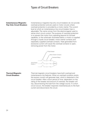
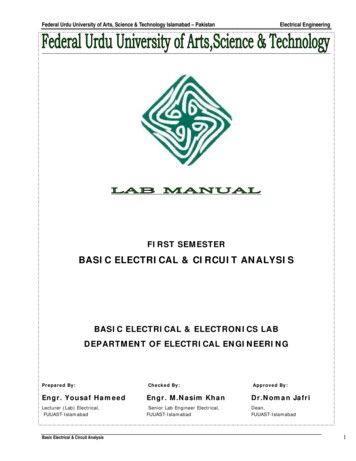
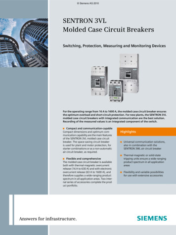
operational life e time of the product, the best way to address such failure is to add diagnostic features into thedesign to take care of the following.1.Infrastructure to detect a fault2.Infrastructure to diagnose and process the fault information and3.A facility to take decision (solution) to address the detected fault.a.Repair faultb.Contain faultSince a fault means non availability of IC function at least temporarily, all four actions described above needto be completed in a reasonable time so that the safety of the overall system is not compromised. This is calledas fault tolerant time interval illustrated in figure [1], and the value depends on the application tOnfaultFaulttoleranttimeintervalFigure 1. Diagnostic cycleA. Infrastructure to detect faultThe infrastructure required for detection of a random hardware fault greatly depends upon the integrated circuitcategory and type. In a passenger vehicle category, this can vary from a1.Front end electronic sensors with integrated analog & mixed signal circuitry along with a digital controlcircuitry2.Microcontroller for engine, body or chassis control3.Application specific integrated circuit for specific applicationsThe electronic sensor category mentioned many times contain high performance analog and mixed signalcircuits such as ADC, DAC, and may even contain RF components. In such systems the basic fault detectioncircuits are built around a set of on chip sensors such as temperature monitors, voltage monitors, ADC clippingsensors, clock monitors etc. The microcontroller category is more prone to soft errors such as instruction memorycorruption. In such cases additional circuits must be built to detect memory corruption, and resulting controllerhung up situations. Memory error detection and correction logic, watch dog units etc. can add value here. In thirdcategory, typically contain multiple processing units along with local and shared memory for inter processorcommunications. Here apart from monitoring individual processor lock up condition, monitoring circuits must bebuilt to monitor inter processor communication, and possible lock up conditions.B. Infrastructure to diagnose and process faultOnce a fault condition is detected, a diagnostic procedure must be initiated and completed in reasonable timeto assess the reason and severity of the fault. This requires some level of intelligence, and a most appropriate3
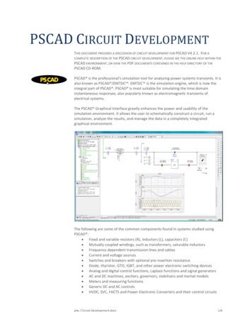
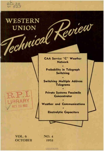
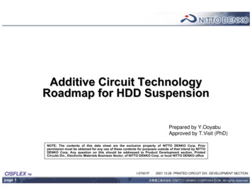
candidate for doing such action is none other than MCU control software. In the absence of a MCU as is the casewith many sensor type integrated circuits, this can be done by explicit hardware diagnostic control FSM.However this can be quite expensive. In such scenario, the safety architecture for diagnosis of fault informationcan be built around the concept of using external MCU with full access to the fault detection units with thesensors.C. Infrastructure to take action against faultThis totally depends on the safety integrity levels and safety class of the integrated circuits. The following arethe few possibilities1.Fail safe operation: This would be the minimum requirement from a functional safety view point. Thefunctional behavior of the integrated circuit must be safe enough from a system view point. Typicalexample would be a simple electronic sensor, once a fault is detected, the sensor can be declared unreliable from a system view point, and the system can look for alternative ways to process theinformation. This may include sensor redundancy at system level.2.Fail operational: In some of the highly safety critical scenario, a functional failure may not be acceptable.In this case the requirement would be to provide fully functional operational behavior against single pointfault or functionality with reduced functions. This indirectly means redundancy at integrated circuitlevel.IV.SAFETY ANALYSYSSince life time failures of integrated circuits are random in nature, and in most cases the reason for failurescan be found through life time test or qualification, it is possible to predict the probability of such failures throughqualitative risk basement and quantify them through quantitative risk basement such as FMEDA (failure modeeffect and diagnostic analysis). Combinations of both qualitative and quantitative assessments are recommendedfor accurate analysis.A. Qualitative risk assessmentFMEA is considered as an efficient qualitative method in assessing the product level risk, starting at an earlyphase of the product development life cycle, and carried throughout the product life cycle and on a continuousevaluation basis. One of the critical aspects of the FMEA flow is the organizational level feedback loop, whereinthe inputs are taken from organizational level quality history of similar products, and the FMEA findings are fedback to the quality history repository for future projects. The quality history consists of lessons learned inprevious projects, field failure reports, benchmarking reports, and expert opinions etc. The FMEA flow andfeedback mechanism is shown in figure[2]. The red lines on the left side of the picture indicate the feedback loopat the project level and the red lines at right indicate the organizational level feedback. FMEA validation is a keyaspect at the organizational level; where in the effectiveness of FMEA is assessed through field failure reports ofthe product.Project levelfeedbackOrganizationallevel feedbackFMEASTARTQualityHistoryIdentify RRequirementProcessVerification& ValidationFigure 2. FMEA cycle4
Within the project the FMEA is conducted at three levels. We will be discussing the first two FMEA items inthis paper. The semiconductor manufacturing itself is considered as a matured process, and if nottheSemiconductor fabrication house along with process flow validation team will be qualifying the process throughvarious test chip programs.Table II. FMEA at project levelFMEA levelsFMEA scopeConcept levelprocessFocuses on potential failure modesassociated with the proposed functions ora concept proposalDesign levelFocuses on potential failure modes ofproducts caused by design deficienciesSemiconductorProcess levelFocuses on potential failure modes of thesemiconductor process that are caused bymanufacturing or assembly processdeficiencies1231) Concept phase FMEAThe primary strategy is to focus on ensuring right information at the conceptual design stage and thenpreserving the information integrity as we proceed through detailed design and implementation stage. We foundthat an early concept level FMEA is a good mechanism to critically evaluate the requirements itself and tovalidate the concept against the system constraints. Focus is on the interaction between systems at concept leveland identifies potential failure modes caused by interactions. This can used to analyze concepts in the early stagesbefore hardware is defined. The following are the benefits of doing an evaluation at an early stage.1.Helps in selecting the optimum concept alternatives, or determine changes to design specifications. Italso can identify system level testing requirements.2.Helps in determining hardware redundancy and fault tolerance requirements based on failure modes andeffects.3.Helps to select the optimum concept alternatives, or determine changes to Design Specifications (DS).The following are the outputs of the concept level FMEA that may influences the system level decisions1.A list of potential concept level Failure modes and causes.2.A list of actions (and to track) to eliminate the causes of Failure Modes, or reduce their rate ofoccurrence.3.Decision on redundancy management (if required).4.Specific operating parameters and boundaries as key specifications in the design phase.5.New test methods or recommendations for new generic testing.6.Decision on which concept to pursue.2) Design phase FMEAHere again apart from the standard design practices, clear attention is given on doing a design level FMEAbased approach in identifying the weak spots in the design. The focus is on identifying potential failure modes ofproducts caused by design deficiencies and the mission profile/boundary conditions of the design. The followingare the generic guidelines followed in conducting the design level FMEA.5
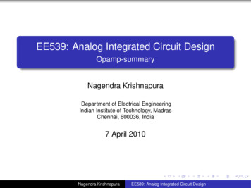
1.Analysis based hardware functions, interfaces, hardware-software interaction ect.2.Consider environmental conditions and its impact on design (EMI/EMC, ESD, Single event upset etc.)3.An identified failure mode may provide additional information to help plan thorough an efficientverification and validation programs.4.It also establishes a priority system for design improvements, provides an open issue format forrecommending and tracking risk reducing actions and future reference to aid in analyzing field concerns.The following are the benefits of the design level FMEA that can also influences the design decisions1.Aiding in the objective evaluation of design, including functional requirements and design alternatives.2.Evaluating the initial design against non-functional requirements (example environmental conditionssuch as ESD, EMI/EMC etc.)3.Providing additional information to aid in the planning of thorough and efficient design, development,and validation programs.4.Developing a ranked list of potential Failure Modes according to their effect on the "customer," there byestablishing a priority system for design improvements, development and validation and analysis.5.Identify Implementation/verification priorities.6.Providing an open issue format for recommending and tracking risk reducing actions by linking FMEAresults CR/PR, risk register etc.7.Providing future reference, e.g., lessons learned, to aid in analyzing field concerns, evaluating designchanges and developing advanced designs.8.Additional information to validate the system specification and V&V plan by linking FMEA items toV&V plan and to requirement management process.The following are the valuable outputs from a design FMEA process.1.A list of potential product failure modes and causes.2.A list of critical characteristics of the system to help in design priority setting3.A list of recommended actions for reducing severity, eliminating the causes of product failure modes orreducing their rate of occurrence, or improving Detection.4.Feedback of design changes to the design communityA critical issue with respect to FMEA is on how we start a FMEA process. The following can be consideredas generic guidelines to get the right information on table to conduct an effective FMEA process.1.Review specifications such as the statement of work (SOW) and the system requirement document(SRD), System configurations, designs, specifications, and operating procedures, Interface informationand functional descriptions.2.Analyze above with respect to key requirements3.Compile information on earlier/similar designs from in-house/customer users such as data flow diagramsand reliability performance data from the company's failure reporting, analysis and corrective actionsystem4.Collect data by interviewing: architecture, design, verification, customer, IP suppliers and outside expertsto gather as much information as possible6
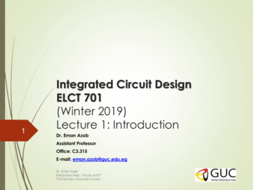
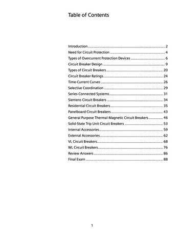
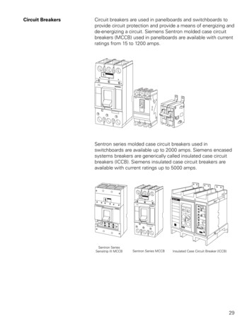
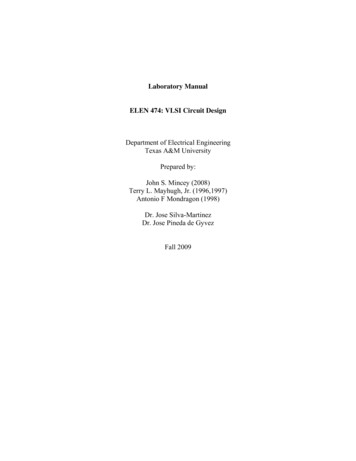
5.Create boundary condition diagram at system level (for Concept FMEA) and functional block diagramfor Design FMEA6.Identify the sensitive areas in integrated circuits. It is easy to start if the SRS/HRS specify safetyrequirements, If not start with a generic way, such as finding a sensible zone (a sensible zone is one of theelementary failure points of the IC in which one or more faults converge to lead a failure). Validdefinitions of sensible zones are, HW–SW interface, memory elements, critical inputs and outputs,critical nets such as clock, complex IP/subsystems, and other key observation emBoundaryConditionsCompanyGuidelinesDesign Concept &recommendationfrom CFMEAFailure report data baseof earlier similar system(Historical Data,lessonslearned)Benchmarkdata if anyData base for FMEAdiscussionsDesign DatabaseDetermine Failure mode(Scope: Technology Risk, Product levelrisk & System level interaction)SeverityOccuranceData base for FMEAanalysisSeverityDetectionFunctional Block diagramFunction analysisFunction failure analysisOccuranceDetectionFMEA worksheet &team reviewCorrectiveaction ical system Characteristics & their validation criteria2.Robustness/reliability checklist & recommended actions for product robustness3.Recommendation on Specific V& V methods4.Recommended actions for Future programsOutput: Recommendation for .1. Specific requirements for System/Subsystem/Component design2. Specific verification/validation criteria3. generic process control4.5.Expert opinion, interviewdata (design, Verification,IP supplier, Customer,outside experts etc.)DetermineFailure modeFMEAworksheet andteam reviewCorrectiveaction requiredDesign Boundary &operational conditionsFigure 3. Concept phase (left) & design phase(right) FMEAB. Quantitative risk assessmentSince majority of hardware failures are due to life time failure and random in nature, it is possible to predictthe probability if failure occurrence and rate through statistical means. Also if there are means to find out faultduring the operational life of the product, then it would be possible to reduce the overall failure rate at the systemlevel. FMEDA (Failure mode effect and diagnostic analysis) is one such technique that can be used at IC level tocompute the random failure metrics such as single point fault metric (SPFM) and latent fault metrics (LFM). Inprinciple the FMEDA can be exercised at product level based on the following information.1.Based on Diagnostics coveragea.Ratio of detectable failures probability against all failure probabilityb.Diagnostic or self-checking elements modelledi. Complete Failure Mode Coverageii. All failure modes of all components must be in the model2.3.Failure Mode Classifications in FMEDAa.Safe or Dangerous: Failure modes are classified as Safe or Dangerousb.Detectable : Failure modes are given the attribute DETECTABLE or UNDETECTABLEc.Four attributes to Failure Modes: Safe Detected(SD), Safe Undetected(SU), DangerousDetected(DD), Dangerous Undetected(DU)Goal : Statistical Safety: based on Safety Integrity Level (ASIL)In addition, the FMEDA need to be supplemented with information from FMEA to associate fault sensitivityinformation based on function criticality. This would provide reasonable scaling facture while computing7
individual component failure data. Similarly field failure data from previous product of life time test data duringproduct qualification can be used for computing the FMEDA metrics more Safetyarchitecture(Diagnosticcoverage)Figure 4. FMEDA processV.DEVELOPMENT PROCESS FOR THE MANAGEMENT OF SYSTEMATIC FAULTSTraditionally it was assumed that majority of hardware failures are random in nature and software failure aresystematic in nature and there is no reason to consider systematic failure types in a hardware only context.However, this is changing with the growing complexity of integrated circuits. Today high level languages areused in describing complex integrated circuit. This means there is a possibility to introduce an error or bug intothe design while specifying the system at a higher abstraction level or while translating the high levelspecification to the actual hardware through various design translation process.Since it is not possible to statistically predict the probability of systematic faults, it is not possible to quantifythe associated risks. Hence the arguments for acceptability of using a complex hardware system are based on thesuitability and maturity of a development life cycle model.The key item of the life cycle is the central planning and control function along with a concurrent processsupport functions based on the following aspects.1.An organizational level product creation process defining clear milestones and gating criteria withinthe project execution life cycle.2.Requirement driven development flow, wherein requirement management and traceability acrosswork product is considered as key to project success.3.A concurrent supporting process to ensure process and product assurance along with 100% forwardand backward traceability to the requirement process.An effective planning process can define a number of gates/milestones, which divide the project up intomanageable project phases. Within these project phases activities will be planned to generate a number ofdeliveries. Each of these deliveries will have their own maturity. It is related to the type of delivery, i.edocument, design, hardware, software, etc. based on the maturity model is applied. The longer implementationphase is further sub divided into different phases based on product maturity expectations. At the end of eachplanned phases, formal reviews and audits are conducted to make sure that the expected process compliance andproduct level maturity are in eviewFigure 5. Product creation StartConcept
Table III. Implementation sub phasesImplementation sub phasesPhaseKey attributesIdentify the key IP’s, componentsand their sources. Risk assessmentPyrite1BronzeEarly prototype state. Freeze thetop level and component levelinterfaces. All individual IP’s areSilver quality.2Interface control for any furthermodule level interface changesSilverFreeze all IP’s. Basic functionalverification OK. All IP’s are ofgold qualityGoldRTL freeze. Functional coverage100 %3A. Compliance driven development process with safety extensionsAn ISO26262 compliant development flow recommend a ‘V’ model project life cycle along with a dedicatedsafety management function. From an implementation perspective, this can be translated into the following1.Safety life cycle on top of standard “V” model with clear input, output and dependency to work productswithin the project2.A dedicated safety organization function at organizational level as well as at the project level to keeptrack of safety related activitiesB. Safety life cycle on top of “V” modelThe key objective is to link the safety related activities into the standard project plan with clear input, outputand dependency to the work products within project. This is shown in figure[7].Figure 6. Safety life cycle on top of project life cycleTable[IV] describes the major extension of activities to the standard ‘V model development process.9
Table IV. Safety extension to project life cycleStandard projectSafety extension to projectSafety extension to projectProof of safetyProject planProject planningProject organization1Development processSafety life cycle activities ( Safetyorg, Safety manager, safety plan,tracking & assessment)Safety case and Safety argumentsSafety team organization &managementRequirement management2Requirement capture &requirementengineering,FMEA(qualitative)Derive Safety goals, safetyrequirements, safety concept, andsafety requirements and methods.FMEA, FMEDA & FTASafety goals, Safety conceptSafety requirements with proof oftraceabilityFMECA/FMEDA/FTA reportsSafety manualVerification & validationProduct assessmentsV&V3Safety V&V, Safety assessment,Tool qualificationReviews/auditSafety V&V reportsSafety assessment reportsValidation reports (proven in useargument)Configuration management and change control4Work productsSafety case as CIBaseline managementImpact analysisfunctions(for CR)ChangemanagementonsafetyBaseline for safety case & safetycase reportsTraceability and impact analysisreport liked to requirementmanagementQM & process assuranceQuality y culture,tailoring,improvementsProject levelContinuousReviewingandcompliance with plans.trackingTool confidence report, Evidenceon safety culture orts,Riskassessmentreports,Periodicconfirmation review reportsIdentifying and documentingdeviations from plans.C. Safety organizationThe primary objective of having a separate safety organization function within the project execution is tocollect evidence to prepare safety case arguments to support the following1.Product claim (random faults): The key metrics such as SPFM, LFM, etc. against the safety classrequirement2.Process claim (systematic faults): To provide confidence in the process development flow along withprocess compliance metrics10
Safety manager(safety plan)Project manager(Integrated project plan with safety extensions)CoordinationSafety extensionsto key functionsSafety teamRequirementmanagementTrackVerification &ValidationConfiguration andchangemanagementQuality management(continuousimprovement)Safety caseFigure 7. Safety organizationOne of the important observation we can make w.r.t the process claim is that, the errors introduced into thework product during the project execution are not random in nature. Hence cannot be supported with anystatistical data. It is more of building confidence into the process flow through an organizational culture withfunctional safety in mind. It is very difficult to implement a safety critical product if the organization is notprepared for it. A well-defined quality management function that focusses on continuous improvement withinorganization and at the project level is the key to the success.Within a project, the process of building a safety critical product can be categorized into the four major area.1.Requirement management2.Design integration3.Verification and validation4.Configuration management and change control5.Quality management and process assurance with continuous improvement1) Requirement managementThere are two important aspects in a requirement driven product development flow.1.There must be a formal agreement with the system development process to asses and evaluate theunderlying hardware requirements, and a mechanism to validate them2.There must be an effective mechanism to track the requirement throughout the product developmentphase to various design and verification items.a.All requirements can be tracked to a design, verification and validation itemb.No design element in repository without an assigned requirementc.Any PR raised can be tracked to a corresponding requirement IDd.Impact on existing requirements can be identified for CRAutomation and tool support is crucial to avert any trivial human errors introduced through manual controland management of requirements. In this project we used commercial requirement management software fromTelelogic named “DOORS”. The following are the critical aspects of requirement management that can be easilymanaged through such tool based requirement management.Table V. Requirement attributesRequirement attribute
ISO 26262 is a functional safety standard based on a more generic IEC 61508 standards for passenger vehicles. The standard provides a well-defined, automotive-specific safety life cycle, with functional safety in mind covering the product life cycle starting from concept phase after production phase. The standard follows a