Transcription
Additive Circuit TechnologyRoadmap for HDD SuspensionPrepared by Y.OoyabuApproved by T.Visit (PhD)NOTE; The contents of this data sheet are the exclusive property of NITTO DENKO Corp. Priorpermission must be obtained for any use of these contents for purposes outside of that intend by NITTODENKO Corp. Any question on this should be addressed to Product Development section, PrintedCircuits Div., Electronic Materials Business Sector, of NITTO DENKO Corp. or local NITTO DENKO officeCISFLEX TMpage 1I-07001P2007.10.26 PRINTED CIRCUIT DIV. DEVELOPMENT SECTION
NITTO Product portfolioProtect ProductsElectrical Insulating TapeDouble Coated TapeSealing MaterialsMedical ProductsFlexible Printed CircuitsÆCircuit technologyDURATACK labelsBandoliering TapesCorrosion ProtectionWafer TapesPolarising FilmsMoulding CompoundsNITOFLON TapesTEMISH ProductsFibre Reinforced PlasticsWith more than 4,000 products, Nitto is available to support Electronicsbusiness with our products. In Flexible Printed Circuit division we cansupport using Subtractive technology and Additive technology.CISFLEX TMpage 2I-07001P2007.10.26 PRINTED CIRCUIT DIV. DEVELOPMENT SECTION
Line-upAdditive Circuit TechnologyAdditive Circuit Technology v.s HDD RoadmapCapability of additive technologyNext challenges of additive technologyCISFLEX TMpage 3I-07001P2007.10.26 PRINTED CIRCUIT DIV. DEVELOPMENT SECTION
Additive Circuit TechnologyAdditive Circuit Technology v.s HDD RoadmapCapability of additive technologyNext challenges of additive technologyCISFLEX TMpage 4I-07001P2007.10.26 PRINTED CIRCUIT DIV. DEVELOPMENT SECTION
Process comparison of both technology¾ Additive technology¾ Subtractive technologySputter Seed Layer (submicron level)Photo resistPhoto-resistLaminationPolyimide pper PlatingCopper PlatingSputter Seed Layer (submicron level)Plated CopperPolyimide filmSSTPhoto resistCuPhoto-resistImagingCuCuEtching ofPlated CopperCuCuPhoto-resistRemovingCuEtching ofSputtered SeedLayerI-07001P2007.10.26CuCuCopper PlatingPhoto-resistRemovingEtching ofSputtered SeedLayerImportant point is Additive is stack up,Subtractive is etch out.CISFLEX TMpage 5PRINTED CIRCUIT DIV. DEVELOPMENT SECTION
Advantages of additive ConductorsSubtractive ConductorsAdditive ConductorsTop widthCopperPolyimidePolyimideConductor Width (um)CrosssectionCopper50454035302520151050Product Lot #Additive methodSubtractive methodSubtractive technology leads to irregular conductor geometry at fine conductor line/ spacing. This impacts:1) Impedance Control2) Ability to achieve conductor lines with 35 um pitch.CISFLEX TMpage 6I-07001P2007.10.26 PRINTED CIRCUIT DIV. DEVELOPMENT SECTION
Additive Circuit TechnologyAdditive Circuit Technology v.s HDD RoadmapCapability of additive technologyNext challenges of additive technologyCISFLEX TMpage 7I-07001P2007.10.26 PRINTED CIRCUIT DIV. DEVELOPMENT SECTION
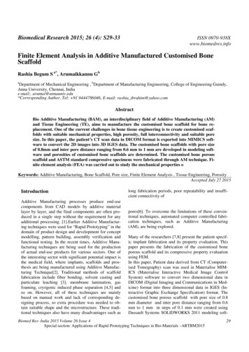
HDD Trend¾Fly height and Areal density400350103002502005150100500020042005 20062007 2008 2009Areal Density[Gb/in2]2]ArealDensity [bit/inchAreal Density[bit/inch1 .00E 13Fly height[nm]Areal Density[Gb/in2]¾ Areal Density Trends154502010AdvancedGMR Head1 .00E 1T 12ADGR:100%1 100.00E G111 .00E 10G101100.00E M08ADGR:60%MR HeadADGR:30%Thin Film Head1 98 5¾Transmission FrequencySignal Grounding er Frequency[GHz]2.5" Frequency[GHz]0.02005CISFLEX TMpage 8200620072008199 0199 520 0020 0520 102 015Year3.02.5LongitudinalMedia1 .00E 10M07Flyheight[nm]PerpendicularMediaGMR Head1 .00E 1G 09TMR/PMRHead3.5" Frequency[GHz]20092010Roadmap- Areal Density Continues to beenabled by PMR !- Lower fly-height require low gimbalstiffness- High frequency transmission circuitÆAdditive is a Must!!I-07001P2007.10.26 PRINTED CIRCUIT DIV. DEVELOPMENT SECTION
Roadmap Circuit¾Write and Read technologyW r itePerpendicularrecordingTFCR ea dTMR HeadPatternedmedia recodingDual Stage ActuatorHeat assisted magneticrecordingCPP HeadLow Fly height, High Speed Data Transmission7 5 Gb/in 2 1 5 0 Gb/in 2 3 0 0 Gb/in 2 6 0 0 Gb/in 2 1 2 0 0 Gb/in 2 2 4 0 0 Gb/in 2¾Requirement for Circuit1. Miniaturization(4Æ6Æ8 11trace)Finer Line and Space by Additive technology2. High Frequency signal(Electrical performance)Ground Plane by Additive technologyCISFLEX TMpage 9I-07001P2007.10.26 PRINTED CIRCUIT DIV. DEVELOPMENT SECTION
Nitto RoadmapMass Production levelPrototypes levelSample production level2007ItemsTrace CQ2CQ3CQ420 /20 um15 /15 umGrounding PadGrounding PlaneSST thickness18 um15 umMin. 12umConductorthicknessMin. 10umMin. 8umCISFLEX TMpage 10I-07001P2007.10.26 PRINTED CIRCUIT DIV. DEVELOPMENT SECTION
Additive Circuit TechnologyAdditive Circuit Technology v.s HDD RoadmapCapability of additive technologyNext challenges of additive technologyCISFLEX TMpage 11I-07001P2007.10.26 PRINTED CIRCUIT DIV. DEVELOPMENT SECTION
Nitto Additive capability¾Trace width history of 00um)1999¾ m10umCrosssectionCISFLEX TMpage 12Nitto’s finer trace capability using Additive technology covers entireSUSPENSION trace width requirement!!!I-07001P2007.10.26 PRINTED CIRCUIT DIV. DEVELOPMENT SECTION
Cu Ground PlaneField coupling to the ground plane.¾ SST Ground PlaneCuElectric Field CouplingSSTCu -¾ Cu Ground PlaneCuPolyimideCu GND PlaneGround Plane(SST)SSTConductivity(S/m)SSTCu1.1*1065.8*108- Ground Plane has current due to electric field coupling. These currentleads to power loss.- Power loss is reduced if conductivity of ground layer is high.ÆCu Ground Plane is most feasible solution for minimizing LOSSES.CISFLEX TMpage 13I-07001P2007.10.26 PRINTED CIRCUIT DIV. DEVELOPMENT SECTION
Cross section of actual sampleBasic structure-1Basic structure-2Skin PolyimideCu Ground PlaneTraceSST etching is availabledue to Skin PITracePolyimideSSTTraceSpace(15um)Trace(15um)Base PISkin PISSTCu Ground PlaneNitto has PI coating technology which enable us to make SST hole under theCu GroundPlane. It is a Must for efficient ImpedanceI-07001P2007.10.26control.PRINTED CIRCUIT DIV. DEVELOPMENT SECTIONCISFLEXTMCu Ground Planepage 14
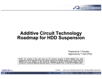
Measurement result(transmission characteristic)0200S-ParameterCu GND Plane-4-6-8w/o Cu GND Plane-10-12w/o GND-PlaneGND-Plane-Sample2GND-Plane-Sample-1GND Plane-Sample3-140246810Frequency [GHz]Cu Ground Plane showsCISFLEX TMpage 15Time Domain Reflectmetory180-2Differential Impedance [Ω]Sdd21(Transmission Characteristic) ipment:VNA,:VNA,TDRTDR1)2)160140120w/o Cu GND Plane10080Cu GND Plane60w/o GND plane40GND Plane-Sample1GND Plane-Sample220GND Plane-Sample30-100102030405060Distance from Probing Point [mm]70Improved signal transmission.Better impedance control.I-07001P2007.10.26 PRINTED CIRCUIT DIV. DEVELOPMENT SECTION
Additive Circuit TechnologyAdditive Circuit Technology v.s HDD RoadmapCapability of additive technologyNext challenges of additive technologyCISFLEX TMpage 16I-07001P2007.10.26 PRINTED CIRCUIT DIV. DEVELOPMENT SECTION
Next challenges of additive technologyBetterSubtractiveRobustness¾High conductivity by pure Copper plating¾Finer Line and SpacingProduct Designflexibility¾Better mechanical propertyAdditiveBetterProduct PerformanceCISFLEX TMpage 17I-07001P2007.10.26 PRINTED CIRCUIT DIV. DEVELOPMENT SECTION
Stress Relaxation of Copper FoilRolled AnnealedElectrodepositedIt has been well established thatElectrodeposited Copper is not asstrong as Rolled AnnealedCopper due to the difference ingrain structure and defectconcentrationsH.D. Merchant, Gould Electronics, 1997CISFLEX TMpage 18I-07001P2007.10.26 PRINTED CIRCUIT DIV. DEVELOPMENT SECTION
Strain Relaxation (%)Nitto Denko High strength CopperHigh StrengthED CuConventionalED CuNitto Denko has been developing new processtechnology to produce high strength highperformance electrodeposited copper to meetthe Fine Line / Spacing of HDD roadmap andthe robustness requirementCISFLEX TMpage 19I-07001P2007.10.26 PRINTED CIRCUIT DIV. DEVELOPMENT SECTION
Nitto Denko High strength CopperCondition10.0%Trace Damage [%]Sample:Conventional ED Copper,High Strength ED CopperTime:10min/20min/30minFrequency: 132kHz7.5%5.0%Conventional ED copper w/oCover PI after 30 mins Test2.5%0.0%10min 20min 30min 10min 20min 30minConventional ED Cu High strength ED CuBy exposing copper trace to ultrasonic DIwater cleaning, conventional ED copperbegins to show cavitation damages after20 mins while high strength ED coppershows no damages even after 30 mins.CISFLEX TMpage 20I-07001PHigh Strength ED copper w/oCover PI after 30 mins Test2007.10.26 PRINTED CIRCUIT DIV. DEVELOPMENT SECTION
Conclusion Nitto Denko 30 um fine line / spacing Additive Technologyis ready to enable the most demanding HDD roadmap inthe market. We are the only supplier of multi-layerconductor line to serve high frequency transmission rate. Higher robustness is required for additive technologyassociated with electrodeposited copper. Nitto Denkobelieves that our recent development of high strengthcopper will meet the most demanding mechanicalrequirement needed to continuously support the HDDroadmap.CISFLEX TMpage 21I-07001P2007.10.26 PRINTED CIRCUIT DIV. DEVELOPMENT SECTION
Thank you very much for your attention.CISFLEX TMpage 22I-07001P2007.10.26 PRINTED CIRCUIT DIV. DEVELOPMENT SECTION
In Flexible Printed Circuit divisionwe can support using Subtractive technology and Additive technology. 2007.10.26 PRINTED CIRCUIT DIV. DEVELOPMENT SECTION page 3 CISFLEX TM I-07001P Line-up Additive Circuit Technology Additive Circuit Technology v.s HDD Roadmap Capability of additive technology Next challenges of additive technology. 2007.10 .