Transcription
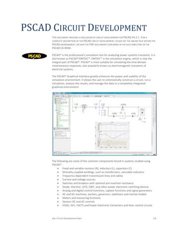
PSCAD CIRCUIT DEVELOPMENTTHIS DOCUMENT PROVIDES A DISCUSSION OF CIRCUIT DEVELOPMENT FOR PSCAD V4.2.1. FOR ACOMPLETE DESCRIPTION OF THE PSCAD CIRCUIT DEVELOPMENT, PLEASE SEE THE ONLINE HELP WITHIN THEPSCAD ENVIRONMENT, OR VIEW THE PDF DOCUMENTS CONTAINED IN THE HELP DIRECTORY OF THEPSCAD CD-ROM.PSCAD is the professional's simulation tool for analyzing power systems transients. It isalso known as PSCAD /EMTDC . EMTDC is the simulation engine, which is now theintegral part of PSCAD . PSCAD is most suitable for simulating the time domaininstantaneous responses, also popularly known as electromagnetic transients ofelectrical systems.The PSCAD Graphical Interface greatly enhances the power and usability of thesimulation environment. It allows the user to schematically construct a circuit, run asimulation, analyze the results, and manage the data in a completely integratedgraphical environment.The following are some of the common components found in systems studied usingPSCAD : Fixed and variable resistors (R), inductors (L), capacitors (C) Mutually coupled windings, such as transformers, saturable inductors Frequency dependent transmission lines and cables Current and voltage sources Switches and breakers with optional pre-insertion resistance Diode, thyristor, GTO, IGBT, and other power electronic switching devices Analog and digital control functions, Laplace functions and signal generators AC and DC machines, exciters, governors, stabilizers and inertial models Meters and measuring functions Generic DC and AC controls HVDC, SVC, FACTS and Power Electronic Converters and their control circuitsplw / Circuit Development.docx1/6
The PSCAD environment has been designed with users in mind; care and attention hasbeen paid to ensure that operations are smooth, fast, and intuitive.E NHANCED W ORKS PACENew views allow you to navigate with more detailed runtime information and files.Most plotting and online control display design, as well as navigational operations cannow be performed directly from the tree view. For example, output and controlchannels may now be dragged and dropped directly from the tree view onto a plot orcontrol panel on the drawing canvas.PSCAD: A COMPREHENSIVE DESIGN AND ANALYSIS ENVIRONMENTAll input, output, and program operations are accessible from the PSCAD Environment. Output can be stored for later analysis by other tools, graph data can becopied and pasted into Excel right from the graph frames, and graphics can be copied byWMF and pasted directly into MS Word to aid report creation.T HE W ORKSPACEThe workspace is used to manage many cases and libraries on one integratedenvironment. The PSCAD Graphical User Interface provides a comprehensive set oftools to perform: Drawing canvas where the circuit is developed, component parameters are set,interactive controls and output plots are all combined into one simulationenvironment Button bars for commonly used components Search tools to quickly find data or errors Output window to view messages and textual output from EMTDC or LineConstants A fully integrated Component Editor to develop your own component andcustom libraries Full F95 Fortran support and support for the Fortran Debug Environments toassist you in locating those pesky bugsplw / Circuit Development.docx2/6
C OMPREHENSIVE M ASTER L IBRARYThe master library of PSCAD , with over 280 flexible and validated components, allowsour users to build advanced nonlinear models of the power system combininggeneration, transmission, power electronics, distribution, and most importantly controlcircuits into one or several large models.A PSCAD model exhibits many of the same behaviours as a real power system – so muchso that engineers and technicians must exercise care in building a simulation model.Components must be correctly wired and appropriate settings provided for proper andexpected operations.Some of the following are key elements contained in our master library.Passive ElementsThe master library contains many fixed and variable resistors (R), inductors (L),capacitors (C), loads, filters, buses, wires, transpositions, and 3-phase breakoutcomponents. All of these components can be assembled in arbitrary fashion. Electricalcomponents are modeled together and solved in EMTDC, and control components areassembled into Fortran statements and are bound to the EMTDC executable.S OURCESA large variety of voltage and current sources are available for use in your simulations.Included are three phase and single phase voltage and current sources, including fixed,variable, or externally controlled. Manual sliders or signal generators can be connectedto these sources to produce any type of signal.plw / Circuit Development.docx3/6
I NPUT /O UTPUTThe master library contains special I/O components in the form of sliders, switches,dials, and buttons. These components are used to manually control your simulation byconnecting and controlling voltage levels, control gains, breaker and fault status, etc.Various output components and constructs are also available.B REAKERSANDF AU LTSThree phase and single phase breakers and various faults, plus associated timingutilities.P OWER E LECTRONICSVarious power electronic elements are contained in this module of the master library.The ability to simulate nonlinear power electronics elements is a core technology of thePSCAD tool set. GTOs, Thyristors, Transistors, IBGTs, Diodes, Lightning Arrestors, 6-pulsebridges, and interpolated firing pulse generators form the basis of the technology. Ageneric SVC model and HVDC controls are also available.CSMF C ONTROLS F UNCTIONSBoth analog and digital controls are available allowing a user to construct any arbitrarycontrol system, simple or complex. These control systems interact with the powersystem, and vice versa providing a power method to study control system behaviour.M ACHINESThis module contains various synchronous 3-phase machines, squirrel cage inductionmachines, wound rotor induction machines, doubly fed induction machines, and IEEEexciters, governors, and power system stabilizers.plw / Circuit Development.docx4/6
T RANSFORMERSThis module contains our single and 3-phase transformers, autotransformers, anduniversal magnetic equivalent core transformer models with both IEC and ANSIrepresentations. Several of the transformers offer on-load tap changer capability.T RANSMISSION L INESANDC ABLESThe most difficult modeling challenge of any time domain simulation program is tomodel Transmission Lines and Cables. Although conceptually simple, the science toeffectively model the Frequency Dependent nature of a transmission line or cablerequires the convergence of many mathematical techniques.The library includes full frequency dependent traveling wave transmission line models inboth the phase and modal domains. A Bergeron transmission line model is alsoprovided which was the first travelling wave model ever developed and useful for 50 or60 Hz studies.S EQUENCER C OMPONENTSSequencer components are part of a special group of control elements, which can becombined together to form a 'Sequence of Events' based on timers, delays and/or otherconditions.M ULTIPLE R UNThis component provides a visual programmable method of running a simulation manytimes for "what if" analysis. Multiple parameters are controllable and many values canbe recorded to determine best run.plw / Circuit Development.docx5/6
O PTIMUM R UNOptimum Run takes advantage of new advancements in multiple run optimizations. Itcomes with Hookes-Jeeves, Golden Section, and Simplex optimization methods tointelligently reduce the number of multiple runs required. A genetic optimizationalgorithm is forthcoming in the next release of PSCAD.plw / Circuit Development.docx6/6
plw / circuit development.docx 1/6 pscad circuit development this document provides a discussion of circuit development for pscad v4.2.1.for a complete description of the pscad circuit development, please see the online help within the pscad environment, or view the pdf documents contained in the help directory of the pscad cd-rom. pscad is the profe