Transcription
Disconnecting Circuit BreakersApplication Guide
2 Introduction ABB Disconnecting Circuit Breakers
Table of contentsApplication Guide (continued)IntroductionIntroduction4LCC (Life Cycle Cost)Reference map5General information26Product portfolio6LCC study of a 145 kV single busbar substation27Symbols and abbreviations7LCC study of a 420 kV breaker-and-a-half substation28Substation designSingle-line diagrams29Single-busbar configurations30Double-busbar configurations32Double-breaker configurations33Refurbishment and extension35Application GuideWhat is a Disconnecting Circuit Breaker?Background and designStandards and testsLayout examples8Single busbar 145 kV3810Single busbar 420 kV39Sectionalized single busbar 145 kV40Sectionalized single busbar 420 kV41Designing safe substationsSubstations without visible gaps12Breaker-and-a-half 145 kV42Earthing switches13Breaker-and-a-half 420 kV43Interlocking in substations14Double breaker 145 kV44Interlocking of disconnecting circuit breakers15Double breaker 420 kV45Ring bus 145 kV46Ring bus 420 kV47Availability and reliabilityGeneral information16Combination 145 kV48Disconnecting link17Double breaker 145 kV, extra compact configuration49Improving availability and reliability in a 145 kV substation18Indoor substation ring bus 145 kV50Improving availability and reliability in a 420 kV substation19Indoor substation single bus 145 kV51Saving space with DCBMaintenance operation procedureGeneral information20Double breaker example52Space comparison in a 145 kV substation21Sectionalized single busbar example53Space comparison in a 420 kV substation22Functional specificationCreating a functional specificationEnvironmental benefitsGeneral information23LCA study 145 kV24www.dcbsubstations.comLCA study 245 kV25Build your own DCB substation5456ABB Disconnecting Circuit Breakers Introduction 3
Disconnecting Circuit BreakerIntegration of a circuit breaker and a disconnector into one unitDevelopment in circuit breaker technology has led to significant decreases inmaintenance and increases in reliability for circuit breakers. Maintenance intervals,requiring de-energizing of the primary circuit, of modern SF6 circuit breakersare 15 years or more. At the same time, development of open air disconnectorshas focused on cost reductions by optimizing the material used, and has notproduced any significant improvements in maintenance requirements and reliability.Reduced maintenance of circuit breakers compared to open air disconnectors ledto the development of the disconnecting circuit breaker, which incorporates thedisconnecting function in the open gap of the circuit breaker contacts.The development program at ABB is strongly focused onproviding added value for our customers. The disconnectingcircuit breaker is an example of this. ABB pioneered the firstever disconnecting circuit breaker installation in 1999, and itwas based on a need by one of our customers.The disconnecting circuit breaker enables smarter, safer andgreener substations due to the removal of conventional disconnectors. Substations equipped with disconnecting circuitbreakers have higher availability in supplying power, theyLTB DCB for 145 kV4 Introduction ABB Disconnecting Circuit Breakersrequire less maintenance and space, and CO2 emissions aregreatly reduced in comparison to conventional substations.ABB has a comprehensive portfolio of disconnecting circuitbreakers, from 72.5 kV all the way up to 550 kV, and theportfolio is being continuously improved. ABB has a solidtrack record of delivering disconnecting circuit breakers to theharshest environments in the world, which is a proof of ABB’stechnological edge.HPL DCB for 420 kV
Reference mapDCB installationsReference countriesArgentinaMexicoAustraliaNew ndRussiaGermanySudanHungarySouth ALithuaniaVietnamABB Disconnecting Circuit Breakers Introduction 5
Product portfolioCompact air insulated HV switchgear withDisconnecting Circuit BreakersABB has a century of experience in building substationsfor high voltage systems. Design and manufacturing of theswitchgear have been constantly refined over the years. Thispermits substations to be built with minimized needs for maintenance and space, low failure rates, increased safety and lowlife cycle costs. The disconnecting circuit breaker is a part ofthis continuous development.Bracket for current transformersA DCB uses a circuit breaker support structure on whicha earthing switch and current transformer can also bemounted. Furthermore, a complete prefabricated busbarstructure - with the necessary primary electrical connections can be also included.Line Entrance ModuleA separate structure called a Line Entrance Module (LEM)is available for supporting apparatus such as voltage transformers, surge arresters and earthing switches.TypeDCB LTB 72.5DCB LTB 145The breaker structure together with an LEM, are normallythe only structures needed to install the HV-apparatus in aswitchgear bay built with a DCB.Primary switchgear apparatusABB offers a complete range of primary apparatus for use inAir Insulated Switchgear. Additional information can be foundin the Application and Buyer’s Guide for each product according to the table below.ProductBuyers GuideLive Tank Circuit Breakers1HSM 9543 22-00enOutdoor Instrument Transformers1HSM 9543 42-00enSurge Arresters1HSM 9543 12-00enApplication GuideLive Tank Circuit Breakers1HSM 9543 23-02enOutdoor Instrument Transformers1HSM 9543 40-00enControlled Switching1HSM 9543 22-01enDCB HPLDCB HPL170-245362 - 420DCB HPL 550DCB LTB 72.5DCB LTB 145with CTwith CTRated voltage, kV72.5145170 - 245362 - 42055072.5145Rated current, A3150315040004000400031503150Circuit breaking current, kARated frequency, 06 Introduction ABB Disconnecting Circuit Breakers
Symbols and abbreviationsSymbolsIn this document the following symbols are used in singleline diagrams.Circuit breakerPresentation of DCB in HMIA new graphic symbol for drawings and illustration has beenadopted and introduced in IEC 60617; see the figure below.Although here is no standard for representation of DCB inHMI, we recommend that the following dynamic illustration beused. The dynamic symbols must be able to demonstrate thedifferent operation modes or sequences for the DCB;DisconnectorDisconnecting Circuit BreakerVoltage transformerDCB symbolCurrent transformerOpenClosedOpenaccording toandIEC 60617LockedSurge arresterAbbreviationsIn this document abbreviations according to the list below are used.Earthing switchSCADA symbolsSUBSTATION1 AAD01AAD01 -QA001SUBSTATION2 -QC001Unlocked -QC0020A0.0 kV0.0 MW0.0 Mvar AAD01AAD010% -QC001Circuit BreakerDCBDisconnecting Circuit BreakerDSDisconnecting SwitchESEarthing Switch/Grounding SwitchSASurge ArresterCTCurrent TransformerCVTCapacitor Voltage TransformerVTVoltage TransformerPIPost InsulatorBBBusbarPTPower TransformerAISAir Insulated SwitchgearGISGas Insulated SwitchgearSF6Sulphur hexafluoride gasOHLOver-head LineCLCable LineSLDSingle Line DiagramLEMLine Entrance ModuleCCCCentral Control CabinetMDF/DL Manual Disconnecting Facility/Disconnecting Link -QB0010A0.0 kV0.0 MW0.0 MvarCB0%IEDIntelligent Electronic DeviceMVMedium VoltageHVHigh VoltageS/SSubstationLCALife Cycle AssessmentLCCLife Cycle CostABB Disconnecting Circuit Breakers Introduction 7
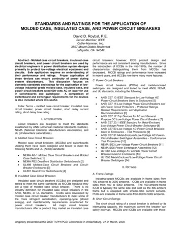
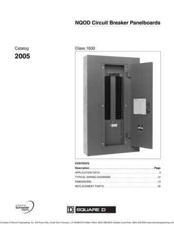
What is a Disconnecting Circuit Breaker?Background and design420 kV air blast circuit breaker420 kV oil minimum circuit breakerBackgroundDevelopment in circuit breaker technology has led to significant decreases in maintenance and increases in reliability forcircuit breakers. Maintenance intervals, requiring de-energizingof the primary circuit, of modern SF6 circuit breakers are 15years or more. At the same time, development of open air disconnectors has focused on cost reductions by optimizing thematerial used, and has not produced any significant improvements in maintenance requirements and reliability. The maintenance interval for the main contacts on open-air disconnectorsis about two to six years, differing between different users anddepending on the amount of pollution due to industrial activities and/or “natural” pollutants such as sand or salt.420 kV SF 6 circuit breakerThe reliability of circuit breakers has increased due to evolution of primary breaking technology, from air blast, oil minimum and SF6 dual-pressure circuit breakers into today’sSF 6 single-pressure circuit breakers. At the same time, thenumber of breaking units per pole has been reduced, andlive tank circuit breakers up to 300 kV are now available withone breaking unit per pole. Removal of grading capacitors forlive tank circuit breakers with two breaking units per pole hasfurther simplified the primary circuit and thus decreased thefailure rate. Circuit breakers up to 550 kV are presently available without grading capacitors, enabling the development ofdisconnecting circuit breakers up to this voltage.Operating mechanisms for circuit breakers have also improved. Since going from pneumatic or hydraulic mechanisms to spring or motorized type mechanisms, maintenancerequirements and failure rates have decreased.Failure and maintenance ratesBulk oil breakersAir blast breakersDisconnectors withopen air contactsMinimum oil breakersSF6 Circuit breakers19502010Development of circuit breakers and correspondingreduction of failure and maintenance rates8 Application Guide ABB Disconnecting Circuit BreakersIn the past, the design principle when building substationswas to “surround” circuit breakers with disconnectors toenable frequent maintenance of the circuit breakers. Due tothe large reduction in failure and maintenance rates for circuitbreakers, the disconnecting function is now more appropriatefor maintenance of overhead lines, power transformers, etc.Reduced maintenance of circuit breakers compared to that ofopen air disconnectors, led to the development of the
disconnecting circuit breaker in close collaboration with someof our major customers. The disconnecting circuit breakercombines the switching and disconnecting functions into onedevice, thus reducing the substation footprint and increasing availability. The first installation of a disconnecting circuitbreaker was in the year 2000. Disconnecting circuit breakers are now available from 72.5 kV to 550 kV and installed inmore than 30 countries around the world.420 kV SF6 disconnecting circuit breakerDesignIn a disconnecting circuit breaker, the normal interrupter contacts also provide the disconnecting function when in the openposition. The contact system is similar to that of a normal circuitbreaker, and there are no extra contacts or linkage systems. Thedisconnecting circuit breaker is equipped with silicone rubberinsulators with hydrophobic properties, i.e. any water on thesurface will form droplets. As a result, they provide excellentperformance in polluted environments and any leakage currentacross the poles in the open position is minimized.The main advantage of the disconnecting circuit breakercompared to a conventional disconnector is that the electrical contacts are enclosed in SF6 gas, as in GIS substations,and thereby protected from the effects of ambient conditions,including the effects of pollution. The protected environmentprovides improved reliability and prolonged intervals betweende-energization for maintenance of the disconnecting circuitbreaker.An important aspect of the disconnecting circuit breaker is itsability to provide safe working conditions during maintenanceand repair work in substations. When the disconnecting circuit breaker is used to isolate other equipment, it needs to belocked in the open position in a fail-safe way. This importantaspect has been considered in the design and specificationof the disconnecting circuit breaker. The locking consists ofelectrical and mechanical locking of the operating mechanism,as well as mechanical locking of the main linkage system forthe breaker pole.145 kV disconnecting circuit breaker. An earthing switch is integrated on thesupport structure. Contact system similar to that of a normal circuit breaker.A disconnecting circuit breaker has to fulfill both applicablecircuit breaker standards and disconnector standards.A specific standard for disconnecting circuit breakers,IEC 62271-108, was issued in 2005.ABB Disconnecting Circuit Breakers Application Guide 9
What is a Disconnecting Circuit Breaker?Standards and testsStandardsIEC (International Electrotechnical Commission) has issued afamily of standards, IEC 62271, for high-voltage switchgear.The specific requirements for disconnecting circuit breakersare given in IEC 62271-108. In addition, the disconnectingcircuit breaker must fulfill the requirements of both the circuitbreaker standard IEC 62271-100, and relevant parts of thedisconnector standard IEC 62271-102. In turn, IEC 62271100 and IEC 62271-102 refer extensively to the commonrequirements stipulated in IEC 62271-1.Important sections in IEC 62271-108 specify how to interlockand secure a disconnecting circuit breaker against unintendedoperation, and also how to verify the dielectric withstand performance after an extended period in service.Indication of positionThe disconnector standard IEC62271-102 includes therequirements that it shall be possible to know the operatingposition, whether open or closed. Two alternative ways ofmeeting this requirement are given: The isolating distance or gap is visible The position of each movable contact ensuring the isolatingdistance or gap is indicated by a reliable visual positionindicating deviceFor disconnecting circuit breakers the second methods isapplied, with a reliable visual position indicating device. Therigidity of the kinematic chain between the main contacts andthe indicating device is verified by a designated type test.Type testsBefore a new disconnecting circuit breaker type is released,numerous tests are performed to verify that it complies withthe requirements of the IEC standards. Once the design of thedisconnecting circuit breaker has been finalized, type testsare performed on some of the first manufactured units. Typetests may be performed at the testing facilities of the manufacturer or at other (independent) laboratories.IEC 62271PartTitle-1Common specifications-100High-voltage alternating current circuit breakers-102Alternating current disconnectors and earthing switches-108High-voltage alternating current disconnecting circuit breakers forrated voltages of 72.5 kV and aboveIEC standards applicable for disconnecting circuit breakers10 Application Guide ABB Disconnecting Circuit BreakersA disconnecting circuit breaker must pass the relevant typetests required for both circuit breakers and disconnectors, asstiplulated in IEC 62271-108.A disconnecting circuit breaker has two different functions— switching current in its function as a circuit breaker, andisolation in its function as a disconnector. The main contacts,the hollow insulator in which they are located and the SF6 gassurrounding the contacts may be affected by the mechanicaland electrical switching operations performed. It is thereforeessential to verify that the design fulfills the dielectric withstand requirements for the isolating distance, applicable for
disconnectors, not only when new but also after an extendedperiod in service. This requirement is verified by the combinedfunction test, specified in IEC 62271-108. In this test, thedielectric withstand capability across the isolating distance isdemonstrated after a mechanical operation test, as well asafter a specified short-circuit test duty.The combined function test consists of one part limited tothe mechanical function, and one part limited to the electricalfunction. These two parts may be performed either separatelyor together in one sequence. The mechanical combined function test is performed with the appropriate number of operations for mechanical endurance class M1 or M2.Routine testsRoutine tests are performed on each disconnecting circuit breaker manufactured to reveal any faults in materials or assembly.Quality controlABB AB, High Voltage Products in Ludvika has an advancedquality management system for development, design, manufacturing, testing, sales and after sales service, as well as forenvironmental standards, and is certified by Bureau Veritas forISO 9001 and ISO 14001.Mechanical combinedfunction testsMechanical operationtest according toIEC 62271-100(M1 or M2)Alternative testmethod limited tomechanical wear only(M1 or M2)Dielectric tests acrossthe isolating distance;test values accordingto IEC 62271-102Short-circuit combinedfunction testsShort circuit testduty T100s accordingto IEC 62271-100Alternative test producingthe same electrical wearDielectric tests acrossthe isolating distance;test values accordingto IEC 62271-102The two parts of the combined function testABB Disconnecting Circuit Breakers Application Guide 11
Designing safe substationsSubstations without visible gapsSubstations without visible gapsOver the years the visible gap provided by disconnectors hasbeen used as an indication of safety when working in AISsubstations. In GIS substations, and with all medium voltageswitchgear, there was no need for a visible gap from the beginning. A reliable indication device (assured by IEC tests) hasbeen used instead for disconnectors and earthing switches.A visible gap itself does not provide sufficient safety to startwork on high voltage equipment. Not until an earth is connected, can work on high voltage equipment be carried out.When the disconnecting circuit breaker is locked in its openposition, it has the same function and dielectric withstand asa traditional disconnector. The safety needed to start workon high voltage equipment is still achieved when the visibleearthing switch is closed.To further enhance safety, it is always recommended toconduct all operations remotely. Substations with disconnecting circuit breakers utilize remotely operated visible earthingswitches for safety measures, rather than the visible gap andportable earthing switches used in conventional solutions.After a sequence of operations (open DCBs, lock DCBs, closeearthing switches), the substation personnel can enter thealready earthed switchyard to padlock all equipment beforethe next work permit is submitted.12 Application Guide ABB Disconnecting Circuit BreakersSafety distancesIEC and other standards prescribe distances in switchgear.Those standard values can sometimes be raised by thecustomer due to local conditions.Special attention must be paid to the distance “to nearestlive part”, also called section clearance. This distance mustbe established between all live parts and the location in theswitchgear where work will be performed.The table shows example values that must always be coordinated with the demands of the actual installation.Example values for distances (mm)72.5 kV145 kV245 kV420 kVLowest insulator base to earth2250225022502250Earth and lowest live part3000377047805480Between phases630130021004200Phase to earth630130021003400Transport way profile700152023503230To nearest live part3000327042804980
Earthing switchesWhere to place earthing switchesDepending on the configuration and voltage level in the substation, the position of the earthing switches differs. Regardlessof substation configuration, it is recommended that an earthingswitch be placed on each busbar in the substation.For single-busbar applications, the earthing switch is normallyinstalled on the same structure as the DCB, and the fixed contact of the earthing switch is installed on the lower connectionflange on the disconnecting circuit breaker (see Figure 1).In systems where the object is fed from two directions, e.g.double-breaker or breaker-and-a-half systems, it is morepractical to use a freestanding earthing switch at the commonconnection point to the object (see Figures 2 and 3). This isbecause the purpose of the earthing switch is to earth theconnected object (line/transformer, etc.) and not the circuitbreaker or other high voltage equipment.Remote operation of the earthing switches is recommendedand a motorized earthing switch should thus be used.Figure 1Figure 2Single busDouble breakerFigure 3Breaker-and-a-halfABB Disconnecting Circuit Breakers Application Guide 13
Designing safe substationsInterlocking in substationThe operation sequence allowed in the substation when utilizing disconnecting circuit breakers is according to the sameprinciples as for a conventional substation. See the examplebelow for assurance that an object is not unintentionally earthed.Once mechanical locking of disconnecting circuit breakershas been carried out, the output signal “disconnecting circuitbreaker locked in open position” is sent to the interlockingEquipment levelLocked inopen positionRelay and protection level14 Application Guide ABB Disconnecting Circuit Breakerssystem. As soon as all other paths feeding the object to beearthed are also disconnected, and the primary voltage atthis point is zero (checked through voltage transformer toensure that the remote line end is open), the interlocking system will produce a release signal that enables the earthingswitch to be closed. Normal safety actions, such as padlocking and labeling of the closed earthing switch, are carried outin the usual way.ZerovoltageandfunctioningEarthing switch can be closedLocked inopen position
Interlocking of disconnecting circuit breakersElectrical interlockingBesides the mechanical locking of an open DCB, electricalinterlockings shall be applied as:DCB closedDCB can operate/perform switching.DCB open and lockingDCB operation locked and interlocked.Locking inactivated and interlocked.activatedLocking device can be operated.Earthing switch open and interlocked.Earthing switch can be operated.DCB open and lockingDCB can operate/perform switching.not activatedLocking device can be operated.Locking device interlocked.Earthing switch open and interlocked.Earthing switch can be operated.Earthing switch closedDCB operation locked and interlocked.Incoming lineOutgoing lineOperating mechanismLocking deviceEarthing switchMMClosing/Tripping coilCloseOpenDCBUnlockedLockedLocking DeviceCloseOpenEarthing SwitchPrinciples of the electrical interlocking system, disconnecting circuit breaker locked in open position. Earthing switch in open position.ABB Disconnecting Circuit Breakers Application Guide 15
Availability and reliabilityGeneral informationAvailability and reliabilityIn today’s electrical transmission and distribution grids, thebiggest concern is in dealing with outages, thus maximizingthe capability to transmit power to end-customers. Outagesare normally due to maintenance but could also be caused byrepair work after failures.The way to maximize the power flow is to use equipment inthe substation with low maintenance requirements, as well assuitable substation configurations.Another major obstacle is in avoiding any blackouts for powerconsumers, or loss of connection to generating power stations. Such events are entirely related to unplanned activitiesdue to a failure of some kind. The “quality” of a certain substation in this respect is often expressed as reliability, or howfailure tolerant it may be. Reliability, such as for an outgoingbay in a substation, is the probability of failure-free powersupply at that point during a specified period of time. Unreliability may be expressed as the expected number of interruptions per year.Improved availability with DCBThe availability of an outgoing bay in a substation, is thefraction of time that electrical power is available at that point.A typical power path through a substation can be divided intothree main parts: line, power transformer and switchgear.Lines and power transformers have relatively high maintenancerequirements. They constitute the chief cause for maintenanceoutages in substations supplied by single radial lines, or withonly a single transformer. In such cases, maintenance ofswitchgear is of secondary importance. On the contrary, ifpower can be supplied from more than one direction and thesubstation is equipped with parallel transformers, the overallunavailability of the substation, due to maintenance, may bedirectly related to the switchgear and the substation configuration. Decisive factors are then the HV equipment used, aswell as the arrangement (single-line diagram) of the substation.16 Application Guide ABB Disconnecting Circuit BreakersThe chief reason for unavailability of a certain part of a substation is maintenance. Unavailability, i.e. the fraction of timethat electric power is not available, is normally expressed inhours per year.In the past, circuit breakers were mechanically and electricallycomplex and therefore required considerable maintenance.The focus was on how to isolate the circuit breaker formaintenance and keeping the other parts of the substationin service. The substations were accordingly built with circuitbreakers surrounded by several disconnectors enable circuitbreaker to be isolated and maintained. Now when moderncircuit breakers require less maintenance than conventionaldisconnectors, substation availability is improved whenconventional disconnectors are removed and disconnectingcircuit breakers are used.Improved reliability with DCBReliability is the probability of failure-free power supply at acertain point during a specified period of time.From the above statement it is clear that only failure frequency,not maintenance in the substation, is taken into considerationwhen looking at reliability. Failure or unreliability of any equipment in the substation is usually considered as the most costly substation event, as it cannot be planned for in advance.The concept of the disconnecting circuit breaker is to eliminateconventional disconnectors and simplify substation design.This minimizes the probability of a failure in a substation.Substations equipped with disconnecting circuit breakers canbe built in a more simplified arrangement than substationswith conventional equipment and still achieve higher reliability.For important substations, it may not be acceptable from asystem security perspective to risk losing the whole substation in the event of a primary fault. To make a substation “immune” against busbar faults and to minimize the disturbancein the event of a primary fault, a breaker-and-a-half or doublebreaker arrangement is commonly used.
Disconnecting linkDisconnecting linkSometimes it can be practical to disconnect a unit from thebusbar or the line during maintenance or repair. This is nota special demand for solutions with disconnecting circuitbreakers, but it has been emphasized as a tool to furtherincrease availability.A disconnecting link, is a point in the substation prepared forfast opening of the primary connection, between disconnectorfor example, or in this case, a disconnecting circuit breakerand the busbar.Removal and reconnection of a disconnecting link in a 420kV substation is estimated to take less than one hour foreach operation.An important factor is that a disconnecting link is not to becompared with a disconnector since it is maintenance freeand is intended to be used only on rare occasions, typicallyonce or twice during the lifetime of the substation.When a disconnecting circuit breaker is isolated in this way,the other parts of the substation may be re-energized duringwork on the disconnecting circuit breaker itself. This increasesthe overall availability of the substation.The disconnecting link consists of standard clamps and awire or tube. The connection points for the disconnecting linkare arranged so that when the disconnecting link is removed,there are necessary safety distances between the isolatedequipment and the busbar or line. The distance shall fulfillspecific requirements in the form of section clearance. Thefigures illustrate with dots, where section clearance is appliedin different substation arrangements.Disconnecting link — OpenA disconnecting link mountedDisconnecting link — Closedon the busbarDouble breakerBreaker-and-a-halfDisconnecting linkABB Disconnecting Circuit Breakers Application Guide 17
Availability and reliabilityImproving availability and reliability in a 145 kV substationAs an example, a comparison is made between a conventional double busbar substation versus a sectionalized singlebusbar arrangement, equipped with disconnecting circuitbreakers and disconnecting links. As the conventional doublebus single breaker and DCB sectionalized single breaker areconnected in the same way during normal service conditions, and busbar switching is typically only carried out dueto scheduled disconnector maintenance, this is a very goodcomparison to make. Assumed maintenance intervals arefive years for open air disconnectors and 15 years for circuitbreakers and disconnecting circuit breakers.Introduction of the disconnecting circuit breakers reduces theaverage unavailability due to maintenance for a single bay inthe substation from 3.07 to 1.2 hours per year. The comparison proves that the reliability of a single bay in the substationwill increase, thus decreasing the failure outage duration from0.17 to 0.15 hours per year.Outage duration (hours/year)Outage duration (hours/year)5.00.33.070.22.51.2The comparison involves:0.04 – Incoming OH lines2 – Power transformers1 – Bus couplerConventional double bus single breaker substation with disconnectorsCircuit breakersanddisconnectorsDisconnectingcircuit breakersMaintenance outage 145 kV0.170.15Circuit breakersanddisconnectorsDisconnectingcircuit breakers0.10.0Failure outage 145 kVSectionalized single bus substation withdisconnecting circuit breakerDisconnecting Circuit BreakerDisconnecting link, to be used during
Circuit breakers 1950 2010 420 kV air blast circuit breaker 420 kV oil minimum circuit breaker 420 kV SF6 circuit breaker The reliability of circuit breakers has increased due to evolu-tion of primary breaking technology, from air blast, oil mini-mum and SF6 dual-pressure circuit breakers into today’s SF6


![[ ANSI C37.20 and NEMA SG-5 ]](/img/5/metal-clad-en.jpg)