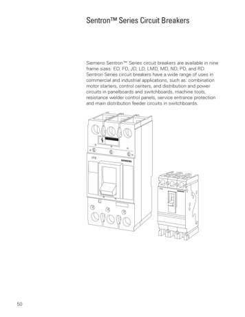
Transcription
Table of ContentsIntroduction. 2Need for Circuit Protection. 4Types of Overcurrent Protection Devices. 6Circuit Breaker Design. 9Types of Circuit Breakers. 20Circuit Breaker Ratings. 24Time-Current Curves. 26Selective Coordination. 29Series-Connected Systems. 31Siemens Circuit Breakers. 34Residential Circuit Breakers. 35Panelboard Circuit Breakers. 43General Purpose Thermal-Magnetic Circuit Breakers. 46Solid-State Trip Unit Circuit Breakers. 53Internal Accessories. 59External Accessories. 62VL Circuit Breakers. 68WL Circuit Breakers. 76Review Answers. 86Final Exam. 88
IntroductionWelcome to another course in the STEP series, SiemensTechnical Education Program, designed to help our distributorsand customers better understand Siemens Industry, Inc.products. This course covers Basics of Circuit Breakers andrelated products.Upon completion of Basics of Circuit Breakers you will be ableto: Explain the need for circuit protection Identify various types of overcurrent protection devices Explain the basic operation of a thermal-magnetic circuitbreaker Describe circuit breaker characteristics shown on a timecurrent curve Define important circuit breaker rating terms Explain why circuit breaker coordination is important Identify internal and external circuit breaker accessories Identify the various types of Siemens circuit breakers Identify circuit protection ratings for various types ofSiemens circuit breakers
This knowledge will help you better understand customerapplications. In addition, you will be better able to describeproducts and determine important differences betweenproducts. You should complete Basics of Electricity beforeattempting Basics of Circuit Breakers. An understanding ofmany of the concepts covered in Basics of Electricity is requiredfor Basics of Circuit Breakers.After you have completed this course, if you wish to determinehow well you have retained the information covered, you cancomplete a final exam online as described later in this course. Ifyou pass the exam, you will be given the opportunity to print acertificate of completion from your computer.Siemens is a trademark of Siemens AG. Product namesmentioned may be trademarks or registered trademarks of theirrespective companies. Specifications subject to change withoutnotice.NFPA70 , National Electrical Code , and NEC are registeredtrademarks of the National Fire Protection Association , Quincy,MA 02169.NEMA is a registered trademark and service mark of theNational Electrical Manufacturers Association, Rosslyn, VA22209.Underwriters Laboratories Inc. and UL are registeredtrademarks of Underwriters Laboratories Inc., Northbrook, IL60062-2096.Other trademarks are the property of their respective owners.
Need for Circuit ProtectionCurrent and TemperatureCurrent flow in a conductor always generates heat. The greaterthe current flow, the hotter the conductor.Normal Current FlowExcessive Current FlowExcess heat is damaging to electrical components. High levels ofheat cause the insulation to breakdown and flake off, exposingconductors. For that reason, conductors have a rated continuouscurrent carrying capacity or ampacity.Good InsulationInsulation Affected by Heat
Excessive current is referred to as overcurrent. An overcurrentmay result from an overload, short circuit, or ground fault.Some circuit breakers provide only short circuit protection, butmost circuit breakers provide protection against short circuitsand overloads, and some circuit breakers provide protectionagainst all three types of overcurrent. Overloads and shortcircuits are discussed in the following paragraphs. Ground faultsare discussed later in this course.OverloadsAn overload occurs when too many devices are operated ona single circuit or when electrical equipment is made to workbeyond its rated capabilities. When an overload occurs, damageto connected equipment or the conductors that supply thatequipment can occur unless the circuit is shut down by anovercurrent protection device. Slight overloads can be allowedto continue for a short time, but as the current magnitudeincreases, the circuit breaker must open faster.Short CircuitsA short circuit is a low resistance path for current created whenbare conductors touch. When a short circuit occurs with voltageapplied, the decrease in resistance results in a short circuitcurrent that can be thousands of times higher than normaloperating current. The heat generated by this current will causeextensive damage to connected equipment and conductorsunless current is interrupted immediately.ConductorInsulationOhm’s Law describes the relationship of current, voltage,and resistance. For example, a 240 volt circuit with 24 Ω ofresistance draws 10 amps of current. When a short circuitdevelops, resistance drops. If resistance drops to 24 milliohms,current increases to 10,000 amps.I ERI 240 V24 ΩI I 10 AI 10,000 A 240 V0.024 Ω
Types of Overcurrent Protection DevicesTo protect a circuit against overcurrents, a protection devicemust detect a fault and automatically disconnect the electricalequipment from the voltage source. An overcurrent protectiondevice must be able to recognize the difference betweenoverloads and short circuits and respond in accordingly. Smalloverloads can be allowed to continue for a short time, but largeroverloads require quicker response, and short circuits must beinterrupted instantaneously.FuseA fuse is a one-shot device. The heat produced by overcurrentcauses the current carrying element to melt open, disconnectingthe load from the source voltage.Good ElementOpen ElementNon-Time-Delay FuseNon-time-delay fuses provide excellent short circuit protection.When an overcurrent situation occurs, heat builds up rapidly inthe fuse. Non-time-delay fuses usually hold 500% of their ratingfor approximately one-fourth second, after which the currentcarrying element melts. This means that these fuses cannot beused in motor circuits, which often have inrush currents greaterthan 500%.Time-Delay FusesTime-delay fuses provide overload and short circuit protection.Time-delay fuses usually allow five times the rated current for upto ten seconds to allow motors to start.
Circuit BreakerCircuit breakers provide a manual means of energizing and deenergizing a circuit and automatic overcurrent protection. Unlikefuses, which must be replaced when they open, a circuit breakercan be reset once the overcurrent condition has been corrected.Pushing the handle to the “OFF” position then back to the “ON”position restores the circuit. If a circuit reopens upon reset tothe “ON” position, the circuit should be checked by a qualifiedelectrician.All circuit breakers perform the following functions: Circuit Breaker OperationSENSE when an overcurrent occurs.MEASURE the amount of overcurrent.ACT by tripping in a timely manner to prevent damage tothe circuit breaker and the conductors it protects.In the following illustration, an AC motor is connected througha circuit breaker to a voltage source. When the circuit breaker isclosed, a complete path for current exists between the voltagesource and the motor allowing the motor to run. Opening thecircuit breaker breaks the path of current flow and the motorstops. The circuit breaker automatically opens when it senses afault. After the fault has been cleared, the breaker can be closed,allowing the motor to operate.Circuit BreakerCircuit Breaker ClosedMotor RunningCircuit Breaker OpenMotor StoppedNote: NEC Article 240 covers overcurrent protection. You areencouraged to become familiar with this material.
Review 11.With an increase in current, heat willa. increaseb. decreasec. remain the same2.Three causes of overcurrent are , , andground faults.3.A is a low resistance path for current createdwhen bare conductors touch.4.An occurs when too many devices areoperated on a single circuit or when electricalequipment is made to work beyond its rated capabilities.5.A circuit breakers provides a means ofenergizing and de-energizing a circuit while alsoproviding overcurrent protection.
Circuit Breaker DesignThe following section presents some basics of circuit breakerdesign. Variations to these design principles are discussedlater in the course. Circuit breakers are constructed from thefollowing five major components: FrameFrame (Molded Case)ContactsArc Chute AssemblyOperating MechanismTrip UnitThe frame provides an insulated housing to mount the circuitbreaker components. The construction material is usually athermal set plastic, such as glass-polymer. The constructionmaterial can be a factor in determining the interruption ratingof the circuit breaker. Typical frame ratings include: maximumvoltage, maximum ampere rating, and interrupting rating.!DANGER!PELIGRODANGER!Type/TypoFrame MGONNMGIType/TipoNJGFrame DGOFF800AONOIType/TipoFrame DGONOFF400A OOFFThree Circuit Breaker Frame Sizes I150AONDG
Straight-Through ContactsThe current flowing in a circuit controlled by a circuit breakerflows through the circuit breaker’s contacts. When a circuitbreaker is turned off or is tripped by a fault current, the circuitbreaker interrupts the flow of current by separating its contacts.Some circuit breakers use a straight-through contactarrangement, so called because the current flowing in onecontact arm continues in a straight line through the othercontact arm.SpringMovable Contact ArmMagnetic FieldStationary Contact ArmBlow-Apart ContactsFieldAs an improvement overMagneticthe straight-throughcontact design,Siemens developed the blow-apart contact design nowcommonly used by circuit breakers with higher interruptingratings. With this design, the two contact arms are positionedparallel to each other, as shown in the following illustration.As current flows through the contact arms, magnetic fieldsdevelop around each arm. Because the current flow in onearm is opposite in direction to the current flow in the otherarm, the two magnetic fields oppose each other. Under normalconditions, the magnetic fields are not strong enough to forcethe contacts apart.Movable Contact ArmStationary Contact Arm10
When a fault develops, current increases rapidly causing thestrength of the magnetic fields surrounding the contactsto increase as well. The increased strength of the opposingmagnetic fields helps to open the contacts faster by forcingthem apart.Movable Contact ArmStationary Contact ArmBy reducing the time required to open circuit breaker contactswhen a fault occurs, the blow-apart contact design reduces thedamaging heat felt by the circuit protected by the circuit breaker.Straight Through ContactsContacts OpenedOvercurrent SensedIPBlow-Apart ContactsTArc Chute AssemblyWhen circuit breaker contacts open, current continues toflow for a short time by arcing across the air space betweenthe contacts. When the contacts open far enough, the arc isextinguished and the current stops.Minimizing the arc is important for two reasons. First, arcing candamage the contacts. Second, the arc ionizes gases inside themolded case. If the arc isn’t extinguished quickly the pressurefrom the ionized gases can cause the molded case to rupture.11
Circuit breakers commonly use an arc chute assembly toquench the arc. This assembly is made up of several “U” shapedsteel plates that surround the contacts. As the arc developes, itis drawn into the arc chute where it is divided into smaller arcs,which are extinguished faster.Arc Chute AssemblyArc Quenched byArc Chute AssemblyOperating HandleAs previously stated, a circuit breaker must provide a manualmeans for energizing and de-energizing a circuit and must becapable of being reset after a fault condition has been cleared.These capabilities are typically provided through use of anoperating handle.Molded case circuit breakers (MCCBs) are trip free, meaning thatthey cannot be prevented from tripping by holding or blockingthe operating handle in the “ON” position. There are threepositions of the operating handle: “ON” (contacts closed), “OFF”(contacts open), and “TRIPPED” (mechanism in tripped position,contacts open). The circuit breaker is reset after a trip by movingthe handle to the “OFF” position and then to the “ON” position.“ON”“TRIPPED”“OFF”Operating MechanismThe operating handle is connected to the moveable contact armthrough an operating mechanism. Siemens molded case circuitbreakers use an over-center toggle mechanism that is a quickmake and quick-break design.12
In the following illustration, the operating handle is movedfrom the “OFF” to the “ON” position. In this process a springbegins to apply tension to the mechanism. When the handleis directly over the center, the tension in the spring is strongenough to snap the contacts closed. This means that the speedof the contact closing is independent of how fast the handle isoperated.Handle in “ON” PositionContacts ClosedHandle in “OFF” PositionContacts OpenThe contacts are opened by moving the operating handle fromthe “ON” to the “OFF” position. In this process, a spring beginsto apply tension to the mechanism. When the handle is directlyover the center, the tension in the spring is strong enough tosnap the contacts open. Therefore, contact opening speed isalso independent of how fast the handle is operated.Handle in “ON” PositionContacts Closed13Handle in “OFF” PositionContacts Open
Trip UnitIn addition to providing a means to open and close its contactsmanually, a circuit breaker must automatically open its contactswhen an overcurrent is sensed. The trip unit is the part of thecircuit breaker that determines when the contacts will openautomatically.In a thermal-magnetic circuit breaker, the trip unit includeselements designed to sense the heat resulting from an overloadcondition and the high current resulting from a short circuit. Inaddition, some thermal-magnetic circuit breakers incorporate a“Push-to-Trip” button.Manual“Push-to-Trip”ButtonAdjusting ScrewTripper BarThermal OvercurrentSensing ElementElectromagnetShort CircuitSensing ElementThermal-Magnetic Trip UnitTrip MechanismThe trip unit includes a trip mechanism that is held in placeby the tripper bar. As long as the tripper bar holds the tripmechanism, the mechanism remains firmly locked in place.Trip MechanismHeld by Tripper BarTripper BarTrip MechanismTrip Mechanism LockedTrip Unit with Trip Mechanism14
The operating mechanism is held in the “ON” position by thetrip mechanism. When a trip is activated, the trip mechanismreleases the operating mechanism, which opens the contacts.Note: the drawings in this section show an AC power source;however, a DC source could also be used.Handle in “ON” PositionOperating Mechanism Heldin Place by Trip MechanismLoadContacts Closed15Power Source
Manual TripSome molded case circuit breakers, especially larger breakers,can be manually tripped by pressing the “Push-to-Trip” buttonon the face of the circuit breaker. When the button is pressed,the tripper bar rotates up and to the right. This allows the tripmechanism to “unlock,” releasing the operating mechanism. Theoperating mechanism opens the contacts.The “Push-to-Trip” button also serves as a safety device bypreventing access to the circuit breaker interior in the “ON”position. If an attempt is made to remove the circuit breakercover while the contacts are in the closed (“ON”) position, aspring located under the pushbutton causes the button to lift upand the breaker to trip.Operating MechanismReleased by Trip MechanismLoadPower Source16
Overload TripThermal-magnetic circuit breakers employ a bimetallic stripto sense overloads. When sufficient current flows throughthe circuit breaker’s current path, heat build up causing thebimetallic strip to bend. After bending a predetermineddistance, the bimetallic strip makes contact with the tripper baractivating the trip mechanism.Operating MechanismReleased by Trip MechanismBimetallic Strip Bendsto Trip the BreakerLoadPower SourceA bimetallic strip is made of two dissimilar metals bondedtogether. The two metals have different thermal expansioncharacteristics, so the bimetallic strip bends when heated.When current flows through a bimetallic strip, heat causesthe strip to bend. The more current, the hotter the bimetallicbecomes, and the more it bends. When the circuit breaker’scontacts open, the bimetallic strip cools and returns to itsoriginal condition. This allows a circuit breaker to be manuallyreset once the overload condition has been corrected.17
Short Circuit TripAs previously described, current flow through a circuit breaker’sblow-apart contacts creates opposing magnetic fields. Undernormal operating conditions, these opposing forces are notsufficient to separate the contacts. When a short circuit occurs,however, these opposing forces increase significantly.The current that flows through the contacts also flows througha conductor that passes close to the circuit breaker’s trip unit.At fault current levels, the magnetic field surrounding thisconductor provides sufficient force to unlatch the trip unit andtrip the breaker.The combined actions of magnetic fields forcing contactsapart while simultaneously tripping the circuit breaker resultin rapid interruption of the fault current. In addition, becausethe magnetic forces are proportional to the current, the greaterthe fault current, the shorter the time it takes to interrupt thecurrent.Operating Mechanism Heldin Place by Trip MechanismShort CircuitFault CurrentBegins to Flow18LoadBreaker TripsInterruptingCurrent FlowLoad
Review 21.When a circuit breaker is turned off or is tripped by afault current, the circuit breaker interrupts the flow ofcurrent by separating its .2.Siemens developed the contact design thatgreatly reduces the amount of time it takes for breakercontacts to open when a fault occurs.3.The assembly reduces contact damage bydividing the arc into smaller segments which can beextinguished faster.4.Siemens circuit breakers use an togglemechanism that ensures that the breaker’s contactswill open or close quickly when a breaker is manuallyoperated.5.A strip is made of two dissimilar metalsbonded together.6.In a thermal-magnetic circuit breaker, a fieldtrips the circuit breaker when a short circuit is sensed.19
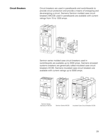
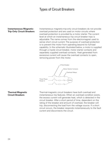
Types of Circuit BreakersInstantaneous MagneticTrip-Only Circuit BreakersAs the name indicates, instantaneous magnetic-trip-onlycircuit breakers provide short circuit protection but do notprovide overload protection. This type of circuit breaker istypically used in motor control applications where overloadprotection is provided by an the overload relay.3-Pole BreakerMotor Starter ContactsOverload Relays3-PhasePower InMotorThermal-MagneticCircuit BreakersAs described previously, a thermal-magnetic circuit breakerhas a trip unit that senses heat to detect an overload and sensesa magnetic field generated by current to detect a short circuit.This type of circuit breaker trips immediately when a shortcircuit occurs, but delays an appropriate amount of time beforetripping in the event of an overload.Interchangeable TripCircuit BreakersThe user cannot change the trip unit in many circuit breakers,but some circuit breakers have an interchangeable trip unit.This feature allows the user to change the continuous currentrating of the breaker without replacing the breaker. This is doneby replacing the trip unit with one of a different rating.Note: Care must be exercised when considering interchangeabletrip circuit breakers. A circuit breaker may be listed byUnderwriters Laboratories, Inc. (UL ) for a specificinterchangeable trip unit only. Circuit breaker frames are usuallydesigned to prevent the installation of an improper trip unit sizeor type.20
Interchangeable Trip UnitMolded Case SwitchSiemens molded case switches employ the same operatingmechanism as the thermal-magnetic and magnetic-only units.However, a preset instantaneous function is factory installed toallow the switch to trip and protect itself at a high fault current,but the switch provides no thermal overload protection or shortcircuit protection.Current LimitingCircuit BreakersMany electrical power distribution systems can deliver largeshort circuit currents to electrical equipment. This high currentcan cause extensive damage. Current limiting circuit breakersprotect equipment by significantly reducing the current flowingin the faulted circuit.One way to accomplish current limiting is with an additionalset of contacts that feature two moveable arms. These dualpivot contacts separate even more quickly than the singlepivot contacts. The dual-pivot contacts are connected in serieswith the single-pivot contacts. As with the single-pivot design,current flows in opposite directions through the contactarms, creating a magnetic repulsion. As current increases, themagnetic repulsion force increases.21
In an overload condition, where current may only be one to sixtimes normal current, the dual-pivot contacts remain closeduntil the breaker trips. However, when a short circuit occurs,fault current is extremely high and both sets of contact armsopen simultaneously, generating high impedance arcs. Thecontact gap of the dual-pivot contacts increases more rapidly,which increases arc impedance more rapidly. Once the arcsare extinguished, the dual-pivot contacts close due to springtension. The single-pivot contacts are held open by the breakermechanism, which tripped during the fault and must bemanually reset.The frame on current limiting circuit breakers of this designis extended to allow room for the dual-pivot set of contacts.Siemens current limiting breakers can handle fault currents ofup to 200,000 amps.Single-Pivot ContactsFrame ExtensionDual-Pivot Contacts22
Solid-State Circuit BreakersSolid-state circuit breakers and thermal-magnetic circuitbreakers have similar contact mechanisms, but their trip unitsare different. A solid-state trip unit not only determines when totrip the circuit breaker, but also has programmable features andimproved accuracy and repeatability.The brain of a solid-state trip unit is a microprocessor.Adjustments on the trip unit set numerical values that themicroprocessor uses in performing protective functions. Currentsensors connected to the trip unit monitor the load current. Thetrip unit continuously compares this current to trip unit settings.When current exceeds a preset value for the selected time, thetrip unit triggers a magnetic latch. The magnetic latch opens thebreaker’s contacts, disconnecting the protected circuit from thepower source.PowerSourceSolid-State Circuit BreakerTripSolid-State SignalTrip tectedCircuit23
Circuit Breaker RatingsVoltage RatingEvery circuit breaker has a voltage rating that designates themaximum voltage it can handle. In other words, the voltagerating of a circuit breaker can be higher than the circuit voltage,but never lower. For example, a 480 VAC circuit breaker couldbe used in a 240 VAC circuit, but a 240 VAC circuit breaker couldnot be used in a 480 VAC circuit. The voltage rating is a functionof the circuit breaker’s ability to suppress the internal arc thatoccurs when the circuit breaker’s contacts open.Some circuit breakers have what is referred to as a “slash”voltage rating, such as 120/240 volts. In such cases, the breakermay be applied in a circuit where the nominal voltage betweenany conductor and ground does not exceed the lower rating andthe nominal voltage between conductors does not exceed thehigher rating.Continuous Current RatingEvery circuit breaker has a continuous current rating, which isthe maximum continuous current a circuit breaker is designedto carry without tripping. This rating is sometimes referred to asthe ampere rating because the unit of measure is amperes, or,more simply, amps.The rated current for a circuit breaker is often represented as In.This should not be confused with the current setting (Ir), whichapplies to those circuit breakers that have a continuous currentadjustment. Ir is the maximum continuous current that a circuitbreaker can carry without tripping for the given continuouscurrent setting. Ir may be specified in amps or as a percentage ofIn.As mentioned previously, conductors are rated for how muchcurrent they can carry continuously. This is commonly referredto as the conductor’s ampacity. In general, the ampacity ofconductors must be at least equal to the sum of any noncontinuous load current plus 125% of the continuous loadcurrent. Conductor ampacity is one of the factors that must beconsidered when selecting and applying a circuit breaker.24
Siemens circuit breakers are rated using 60 C or 75 Cconductors. This means that even if a conductor with a highertemperature rating is used, the ampacity of the conductor mustbe figured on its 60 C or 75 C rating.Frame SizeThe circuit breaker frame includes all the various componentsthat make up a circuit breaker except for the trip unit. For anygiven frame, circuit breakers with a range of current ratingscan be manufactured by installing a different trip unit for eachrating. The breaker frame size is the highest continuous currentrating offered for a breaker with a given frame.Interrupting RatingCircuit breakers are also rated according to the maximum levelof current they can interrupt. This is the interrupting rating orampere interrupting rating (AIR). Because UL and IEC testingspecifications are different, separate UL and IEC interruptingratings are usually provided.When designing an electrical power distribution system, a maincircuit breaker must be selected that can interrupt the largestpotential fault current that can occur in the selected application.The interrupting ratings for branch circuit breakers must alsobe taken into consideration, but these interrupting ratings willdepend upon whether series ratings can be applied. Seriesconnected systems are discussed later in this course.The interrupting ratings for a circuit breaker are typicallyspecified in symmetrical RMS amperes for specific ratedvoltages. As discussed in Basics of Electricity, RMS standsfor root-mean-square and refers to the effective value of analternating current or voltage. The term symmetrical indicatesthat the alternating current value specified is centered aroundzero and has equal positive and negative half cycles. Siemenscircuit breakers have interrupting ratings from 10,000 to200,000 amps.25
Time-Current CurvesTime in SecondsTime-current curves, similar to the one shown on the followingpage, are used to show how fast a breaker will trip at anymagnitude of current. The following illustration shows howto read a time-current curve. The figures along the bottom(horizontal axis) represent multiples of the continuous currentrating (In) for the breaker. The figures along the left side (verticalaxis) represent time in seconds.Multiple of InTo determine how long a breaker will take to trip at a givenmultiple of In, find the multiple on the bottom of the graph anddraw a vertical line to the point where it intersects the curve.Then draw a horizontal line to the left side of the graph and findthe time to trip. For example, in this illustration a circuit breakerwill trip when current remains at six times In for 0.6 seconds.Note that the higher the current, the shorter the time the circuitbreaker will remain closed. Time-current curves are usuallydrawn on log-log paper. Many time-current curves also show thebandwidth, tolerance limits, of the curve.From the information box in the upper right hand corner, notethat the time-current curve illustrated on the next page definesthe operation of a Siemens MG frame circuit breaker. For thisexample, operation with an 800 ampere trip unit is shown, but,depending upon the specific breaker chosen, this circuit breakermay be purchased with a 600, 700, or 800 amp continuouscurrent rating.26
Time Current Characteristics CurveSIEMENS MG Frame Circuit BreakerThermal Magnetic Trip Unit 525 3-PoleFor application and coordination purposes only.Based on 40oC ambient, cold start. Testedin open air with current in all poles.The Curve shown is for I n 800 Amps @ 480VInterruption RatingsIiIn 800 A40o CTM 6250AmpsTrip Unit 5256500IiIn 700 A40o CTM 3250AmpsTrip Unit 5256500IiIn 600 A40o CTM 275027Amps5500Trip Unit 525
Overload ProtectionThe top part of the time-current curve shows the continuouscurrent performance of the circuit breaker. The black lineshows the nominal performance of the circuit breaker andthe gray band represents possible variation from this nominalperformance that can occur even under specified conditions.Using the example of an MG breaker with an 800 ampcontinuous current rating (In), note that the circuit breaker canbe operated at 800 amps (1.
Basics of Circuit Breakers. and related products. Upon completion of . Basics of Circuit Breakers. you will be able to: Explain the need for circuit protection Identify various types of overcurrent protection devices Explain the basic operation of a thermal-magnetic circuit breaker Describe circuit breaker characteristics shown .