Transcription
EE539: Analog Integrated Circuit DesignOpamp-summaryNagendra KrishnapuraDepartment of Electrical EngineeringIndian Institute of Technology, MadrasChennai, 600036, India7 April 2010Nagendra KrishnapuraEE539: Analog Integrated Circuit Design
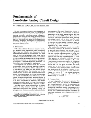
Differential pair opampVddM3M4IrefoutinpM1M2innI0M0Nagendra KrishnapuraEE539: Analog Integrated Circuit Design
Differential pair opampGmGoutAoAcmCiωupk , zkSvi2σVosVcmVoutSRIsupplygm1gds1 gds3gm1 /(gds1 gds3 )gds0 /gm3Cgs1 /2gm1 /CLp2 gm3 /(Cdb1 Cdb3 2Cgs3 ); z1 2p216kT /3gm1 (1 gm3 /gm1 )22 2σVT1 (gm3 /gm1 ) σVT 3 VT 1 VDSAT 1 VDSAT 0 Vdd VDSAT 3 VT 3 VT 1 Vcm VT 1 Vdd VDSAT 3 I0 /CLI0 IrefNagendra KrishnapuraEE539: Analog Integrated Circuit Design
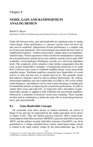
Cascode output resistanceRout gmc/gdscgm1 1/gdsc 1/gm1(negligible)Rout gmc/gdscGs 1/Gs 1/gdscRout gmc/gdscgds1 1/gdsc 1/gds1VbiascVbiascRout 1/gdsc(1 gmc/gm1)Vdd(negligible)McGsVbias1McGs gds1M1VbiascMcM1Vbias1Gs gm1differential pair: Mc degeneratedby M1’s source impedance (gm1)Output resistance looking into one side of the differentialpair is 2/gds1 (gm 1 gm c in the figure)Nagendra KrishnapuraEE539: Analog Integrated Circuit Design
Opamp: dc small signal analysisBias values in blackIncremental values in redImpedances in blueTotal quantity Bias incrementNagendra KrishnapuraEE539: Analog Integrated Circuit Design
Differential pair: Quiescent conditionM3VddM3M4M4I0/2I0/2VcmM1I0/2M2VddVdd-VGS3 (by symmetry)I0/2VcmVcmVbias0M1zero currentI0/2M2Vcm Vdd-VGS3Vbias0Nagendra KrishnapuraEE539: Analog Integrated Circuit Design
Differential pair: TransconductanceM3M4Vddgmvd/2I0/2Vcm vd/2gmvdI0/2gmvd/2M1gmvd/2I0/2M2Vcm-vd/2 Vdd-VGS3vx 0Vbias0Nagendra KrishnapuraEE539: Analog Integrated Circuit Design
Differential pair: Output VddvTgds1/2 vTgds3vTgds1/2Vcm vT(gds1 gds3)Vdd-VGS3 vTVbias0Nagendra KrishnapuraEE539: Analog Integrated Circuit Design
Telescopic cascode: Quiescent conditionM3M4VddI0/2Vbiasp2M7M8zero currentM5 M6Vdd-VGS3Vbiasn2I0/2VcmM1I0/2M2VcmVbias0Nagendra KrishnapuraEE539: Analog Integrated Circuit Design
Telescopic cascode: gmvdgmvd/2gmvd/2M5M6Vdd-VGS3Vbiasn2I0/2Vcm vd/2M1 gmvd/2I0/2M2Vcm-vd/2vx 0Vbias0Nagendra KrishnapuraEE539: Analog Integrated Circuit Design
Telescopic cascode: Output M6vTgds5gds1/2gm5 vTgds7gds3/gm7vTgds5gds1/2gm5 gds1/2vT(gds5gds1/gm5 gds7gds3/gm7)Vdd-VGS3 vTVcmvTgds5gds1/2gm5Vbias0Nagendra KrishnapuraEE539: Analog Integrated Circuit Design
Folded cascode: Quiescent conditionM9M10I0/2 I1VddI0/2 I1M5Vbiasp1M6I1Vbiasp2I1zero currentI0/2VcmM1Vbias0I0/2M2VcmM7M8Vbiasn2I1 VGS3I1M3M4Nagendra KrishnapuraEE539: Analog Integrated Circuit Design
Folded cascode: TransconductanceM9M10I0/2 I1M5gmvd/2gmvd/2I0/2Vcm vd/2M1M6I1gmvd/2VddI0/2 asn2-vd/2 VGS3vx 0Vbias0gmvd/2I1I1M3gmvd/2M4Nagendra KrishnapuraEE539: Analog Integrated Circuit Design
Folded cascode: Output conductanceM9M10vTgds5gds1/2gm5vTgds5gds1/2gm5I0/2 I1I0/2VcmM1M5M2Vbiasp1M6I1I0/2VddI0/2 I1Vbiasp2I1gds1/2vTgds5(gds1/2 gds9)/gm5zero currentM7VcmM8Vbiasn2 vT(gds5(gds1 gds9)/gm5 gds7gds3/gm7)VGS3 vTVbias0vTgds5gds1/2gm5I1I1M3vTgds5gds1/2gm5 vTgds7gds3/gm7M4Nagendra KrishnapuraEE539: Analog Integrated Circuit Design
Differential pair: Noisein0/2 in1/2-in2/2 in3in0/2 in1/2-in2/2 in3in3in4in0/2 in1/2-in2/2in1in2Vcmin0/2 in1/2-in2/2in1-in2 in3-in4in0/2-in1/2 in2/2 Vdd-VGS3Vcmin0in0/2-in1/2 in2/2in0Carry out small signal linear analysis with one noisesource at a timeAdd up the results at the output (current in this case)Add up corresponding spectral densitiesDivide by gain squared to get input referred noiseNagendra KrishnapuraEE539: Analog Integrated Circuit Design
Telescopic cascode as0Nagendra KrishnapuraEE539: Analog Integrated Circuit Design
Telescopic cascode opampGmGoutAoAcmCiωupk , zkp2,4Svi2σVosVoutSRIsupplygm1gds1 gds5 /gm5 gds3 gds7 /gm7gm1 /(gds1 gds5 /gm5 gds3 gds7 /gm7 )gds0 /gm3Cgs1 /2gm1 /CLp2 gm3 /(Cdb1 Cdb3 2Cgs3 )p3 gm5 /Cp5p4 gm7 /Cp7appear for one half and cause mirrror zeros16kT /3gm1 (1 gm3 /gm1 )22 2σVT1 (gm3 /gm1 ) σVT 3 Vbiasn1 VT 5 Vbiasp1 VT 7 I0 /CLI0 IrefNagendra KrishnapuraEE539: Analog Integrated Circuit Design
Folded cascode iasn2Vbias0M3Nagendra KrishnapuraM4EE539: Analog Integrated Circuit Design
Folded cascode opampGmGoutAoAcmCiωupk , zkSvi2σVosVoutSRIsupplygm1(gds1 gds9 )gds5 /gm5 gds3 gds7 /gm7gm1 /((gds1 gds9 )gds5 /gm5 gds3 gds7 /gm7 )gds0 /gm3Cgs1 /2gm1 /CLp2 gm3 /(Cdb1 Cdb3 2Cgs3 )p3 gm5 /Cp5p4 gm7 /Cp7p2,4 appear for one half and cause mirrror zeros16kT /3gm1 (1 gm3 /gm1 gm9 /gm1 )22 22 2σVT1 (gm3 /gm1 ) σVT 3 (gm9 /gm1 ) σVT 9 Vbiasn1 VT 5 Vbiasp1 VT 7 min{I0 , I1 }/CLI0 I1 IrefNagendra KrishnapuraEE539: Analog Integrated Circuit Design
Body effectAll nMOS bulk terminals to groundAll pMOS bulk terminals to VddAcm has an additional factor gm1 /(gm1 gmb1 )gm5 gmb5 instead of gm5 in cascode opamp resultsgm7 gmb7 instead of gm7 in cascode opamp resultsNagendra KrishnapuraEE539: Analog Integrated Circuit Design
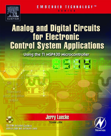
Two stage opampbiasstage 1stage dra KrishnapuraM12EE539: Analog Integrated Circuit Design
Two stage opampVddgm1inp inn M11single stageopampoutRcCcI1First stage can be Differential pair, Telescopic cascode, orFolded cascode; Ideal gm1 assumed in the analysisSecond stage: Common source amplifierFrequency response is the product of frequency responsesof the first stage gm and a common source amplifier drivenfrom a current sourceNagendra KrishnapuraEE539: Analog Integrated Circuit Design
Common source amplifier: Frequency responseVo (s)Vd (s) a3 a2 a1 gm 1 gm 11 sCc (Rc 1/gm 11 ) 1(1)G1 GLa3 s 3 a 2 s 2 a 1 s 1Rc C1 CL Cc(2)G1 GLC1 Cc Cc CL CL C1 Rc Cc (G1 CL C1 GL )(3)G1 GLCc (gm 11 G1 GL G1 GL Rc ) C1 GL G1 CL(4)G1 GLG1 : Total conductive load at the inputGL : Total conductive load at the outputC1 : Total capacitive load at the inputCL : Total capacitive load at the outputNagendra KrishnapuraEE539: Analog Integrated Circuit Design
Common source amplifier: Poles and zerosp1 p2 p3z1G1gm 111 G1 Rc ) C1 (1 GGL 1 GL ) CLccgm 11 C1C C GL G1 CC1c C G1GL Rc C1C CccC Rc Cc (G1 CL GL C1 )C1 Cc C LC1 CcCc CLCc ( G1GL 111 CL CcC11 (1/gm 11 Rc )Cc1Rc G1 GL C1CL (5)(6)(7)(8)Unity gain frequencyωu Cc 1 GLgm 11 G1gm 11Nagendra Krishnapura gm 1 G1 GL Rcgm 11 (9) C1 gGmL gGm11111EE539: Analog Integrated Circuit Design
Common source amplifier: Frequency responsePole splitting using compensation capacitor Ccp1 moves to a lower frequencyp2 moves to a higher frequency (For large Cc ,p2 gm 11 /CL )Zero cancelling resistor Rc moves z1 towards the left half splane and results in a third pole p3z1 can be moved to with Rc 1/gm 11z1 can be moved to cancel p2 with Rc 1/gm 11 (needs tobe verified against process variations)Third pole p3 at a high frequencyPoles and zeros from the first stage will appear in thefrequency response—Ym1 (s) instead of gm 1 in Vo /ViaboveMirror pole and zeroPoles due to cascode amplifiersNagendra KrishnapuraEE539: Analog Integrated Circuit Design
Compensation cap sizingp2 cgm 11 C1C CcC1 CcC1 CC CLgm1CcPhase margin (Ignoring p3 , z1 , . . .)ωu φMgm11gm1 tan 1 p2 ωu(10)(11)(12) p2 tan φM(13)ωu 2 CcCcC1C 1 tan φM 1 tan φM (14)CLCLCLCLFor a given φM , solve the quadratic to obtain Cc /CLIf C1 is very small, p2 gm2 /CL ; further simplifiescalculationsNagendra KrishnapuraEE539: Analog Integrated Circuit Design
Two stage opampAoAcmCiωupk , zkSvi2σVosVcmVoutSR SRIsupplygm1 gm11 /(gds1 gds3 )(gds11 gds12 )gds0 gm11 /gm3 (gds11 gds12 )Cgs1 /2gm1 /CcSee previous pages 16kT /3gm1 (1 gm3 /gm1 )22 2 σVT1 (gm3 /gm1 ) σVT 3 VT 1 VDSAT 1 VDSAT 0 Vdd VDSAT 3 VT 3 VT 1 VDSAT 12 Vdd VDSAT 11I0 /Ccmin{I0 /Cc , I1 /(CL Cc )}I0 I1 IrefNagendra KrishnapuraEE539: Analog Integrated Circuit Design
Opamp r Telescopiccascode Nagendra KrishnapuraFoldedcascode highhigh Twostage EE539: Analog Integrated Circuit Design
Differential pairVddM3M4IrefoutinpM1M2innI0M0Low accuracy (low gain) applicationsVoltage follower (capacitive load)Voltage follower with source follower (resistive load)In bias stabilization loops (effectively two stages infeedback)Nagendra KrishnapuraEE539: Analog Integrated Circuit Design
Telescopic bias0Low swing circuitsSwitched capacitor circuitsCapacitive loadDifferent input and output common mode voltagesFirst stage of a two stage opampOnly way to get high gain in fine line processesNagendra KrishnapuraEE539: Analog Integrated Circuit Design
Folded Vbiasn2Vbias0M3M4Higher swing circuitsHigher noise and offsetLower speed than telescopic cascodeLow frequency pole at the drain of the input pairSwitched capacitor circuits (Capacitive load)First stage of a two stage class AB opampNagendra KrishnapuraEE539: Analog Integrated Circuit Design
Two stage opampbiasstage 1stage ghest possible swingResistive loadsCapacitive loads at high speed“Standard” opamp: Miller compensated two stage opampClass AB opamp: Always two (or more) stagesNagendra KrishnapuraEE539: Analog Integrated Circuit Design
Opamps: pMOS versus nMOS input stagenMOS input stageHigher gm for the same currentSuitable for large bandwidthsHigher flicker noise (usually)pMOS input stageLower gm for the same currentLower flicker noise (usually)Suitable for low noise low frequency applicationsNagendra KrishnapuraEE539: Analog Integrated Circuit Design
Fully differential half circuitsTwo identical half circuits with some common nodesTwo arms of the differential input applied to each halfTwo arms of the differential output taken from each halfNagendra KrishnapuraEE539: Analog Integrated Circuit Design
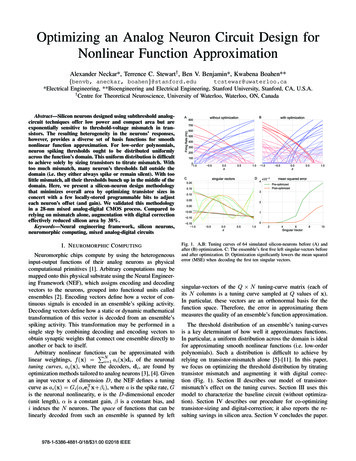
Differential half circuitLine of symmetryM3M4-vo/2Vcm vd/2M3vo/2M1M2M0-vo/2Vcm-vd/2vd/2zero incrementdue to symmetryand linearityM1Differentialhalf circuitSymmetricallinear (or small signal linear) circuit under fullydifferential (antisymmmetric) excitationNodes along the line of symmetry at 0 V (symmetry,linearity)Analyze only the half circuit to find the transfer functionNagendra KrishnapuraEE539: Analog Integrated Circuit Design
Common mode half nbiasM0pbiasM1,2M0Symmetricalcircuit (maybe nonlinear) under common mode (symmmetric)excitationNodes in each half at identical voltages (symmetry)Fold over the circuit and analyze the half circuitNagendra KrishnapuraEE539: Analog Integrated Circuit Design
Common mode orM3vomnbiasvop vom2Vo,cm M0Fully differential opampCommon mode feedback circuitCommon mode feedback circuit for setting the biasDetect the output common mode and force it to be Vo,cmvia feedbackNagendra KrishnapuraEE539: Analog Integrated Circuit Design
Common mode feedback loopbreak the loop foranalyzing cmfb loop vopM2vop vom2vimVo,cm M0Common mode feedback loop has to be stableAnalyze it by breaking the loop and computing the loopgain with appropriate loading at the broken pointApply a common mode step/pulse in closed loop andensure stabilityNagendra KrishnapuraEE539: Analog Integrated Circuit Design
Fully differential circuits: Noisein3M3M4CMFB-VcmM1in3in4vn,half vn,fullin1M3in2M2VcmM1in1half circuit(small signal)M0Sn,full 2Sn,halfCalculate noise spectral density of the half circuitMultiply by 2 Nagendra KrishnapuraEE539: Analog Integrated Circuit Design
Fully differential circuits: Offsetvoff,fullM1M4M3 VT3voff,half VT2M2Vcm VT1 - VT1 VT4 VT3 Vcm M3 VddM1half circuit(small signal)M0v2off,full 2v2off,halfCalculate mean squared offset of the half circuitMultiply by 2 if mismatch (e.g. VT ) wrt ideal device isusedNagendra KrishnapuraEE539: Analog Integrated Circuit Design
Fully differential circuits: OffsetVddM3 M4 M3 VT34voff,fullM1 M2Vcm VT12 Vcm- VT12 VT34voff,halfM1half circuit(small signal)M0v2off,full v2off,halfCalculate mean squared offset of the half circuitMultiply by 1 if mismatch between two real devices isusedNagendra KrishnapuraEE539: Analog Integrated Circuit Design
EE539: Analog Integrated Circuit Design Opamp-summary Nagendra Krishnapura Department of Electrical Engineering Indian Institute of Technology, Madras Chennai, 600036, India 7 April 2010 Nagendra Krishnapura EE539: Analog Integrated Circuit